Shortwave listening and everything radio including reviews, broadcasting, ham radio, field operation, DXing, maker kits, travel, emergency gear, events, and more
Many thanks to the folks at KMTS who share the following:
A studio version of the KMTS Boot Up Special of 17.1.2021 on 7780 kHz at 0100 UTC. This transmission consisted of Country and Western sounds, engineer test signals, rare re-media mixes of cult radio favourites, strange tones, and vox.
Rebroadcasts: 7 pm eastern time Sunday January 17th 2021 and Sunday January 24th 2021 (0:00 UTC Monday 1/18 and 1/25 on 9395 kHz.
Many thanks to SWLing Post contributor, Istvan Biliczky with the TOP DX Radioclub, who shares the following results from the 2020 Top DX contest (click image to enlarge)
Many thanks to SWLing Post contributor, Kostas (SV3ORA), for sharing the following guest post which originally appeared on his radio website:
Emergency transmitter: An 8-component, high-power 40m/30m transmitter to get you quickly on the air
by Kostas (SV3ORA)
Introduction
QRP is all about doing more with less. This is more than true, with the construction of this cheap, simplistic transmitter presented here. It is designed primarily as an emergency transmitter (EMTX) that can be built or serviced in the field or at any home. However, it can be used as a HAM radio transmitter as well. Do not judge by its low components count though. This transmitter is powerful, more powerful than anything the QRPers would dream of. It is just remarkable how 8 components can lead in so much output power, that lets you communicate with a big part of the world, when propagation conditions are right. It is very difficult for a circuit to match that kind of simplicity in balance with such performance.
Following my detailed instructions, the EMTX can be reproduced easily, within hours. The result is always success, this is one of the circuits that are not critical at all and a successfully working transmitter can be reproduced every time. I have built this transmitter several times, using similar components (even toroids) and it always worked. The transmitter meets the next expectations:
1. Output power (including harmonics): A few mW up to 15W (depended on transistor, crystals and voltage/current used) at 50 ohm.
2. It can drive any antenna directly, 50 ohm or higher impedance, without external tuners.
3. Bands of operation: Currently 40m, 30m
4. Mode: CW, Feld-Hell (with external switching circuit), TAP code and any other ON/OFF keying mode. AM modulation has been easily applied too.
5. Options like reverse polarity protection diode (useful in the field when testing different unknown polarities PSUs) and current meter (for easier tuning) are available.
The challenge
The purpose of this transmitter is to be used primarily as an emergency transmitter. This poses several challenges that influence the design of the transmitter:
1. It must be able to be built or serviced easily in the field or at any home, with components that could be salvaged from near by electronics sources or a small electronics junk box. This means that components count should be kept very low and they must not be rare to find but commonly available parts. As a side effect cost would also be kept small, if one is to buy any component. Also, the active components must be interchangable with many other devices without the need for the design or the rest of the circuit components to be changed.
2. It must be able to operate from a very wide range of DC voltage sources and at relatively low current, so that common house power supplies could be used to supply power to it. Such devices include linear or switched mode power supplies from laptop computers, routers, printers, cell phone chargers, Christmas lights or any other device one might have available.
3. It must be capable of transmitting a powerful signal, so that communication is ensured. An emergency transmitter that is capable of a few mW of output power, might be heard locally (still useful, but there are handheld devices for that already) but isn’t going to be of much usage if it can’t be heard really far away.
4. It must be capable of loading any antenna without external equipment required. In an emergency situation, you just don’t have the luxury of building nice antennas or carrying coaxial cables and tuners. There may be even extreme cases where you can’t even carry a wire antenna and you depend on salvaging wire from sources in the field to put out a quick and dirty random wire antenna.
5. Adjustments of the transmitter should be kept minimum without the help of any external equipment and there must be indication of the correct operation of the transmitter or the antenna in the field.
Components selection
The transistor:
This transmitter has been designed so that it can operate with any NPN BJT in place. This includes small signal RF and audio transistors and high power RF transistors like the ones used on HF amplifiers and CB radios. Despite 2sc2078 is shown in the schematic, just try any NPN BJT in place and adjust the variable capacitor accordingly. When you are in the field, you do not have the luxury of finding special types of transistors. The transmitter must operate with any transistor in hand, or salvaged from near-by equipment. Of course the power capability of the transistor (as well as the crystal current handling) will determine the maximum VCC and current that can be applied to it and hence the maximum output power of the transmitter. Some of the most powerful transistors I have used, come out of old CB radios, such as the 2sc2078, 2sc2166, 2sc1971, 2sc3133, 2sc1969 and 2sc2312. There are many others. As an example, the 2sc2078 with a 20v laptop PSU, gave 10-12W of maximum output power into a 50 ohms load.
Schematic of the 8 components EMTX for the 40m/30m bands. Components with gray color are optional.
The crystal:
This is the most uncommon part of the transmitter. You have to find the crystal for the frequency that you want to operate on. Crystals within the 40m or 30m CW segments are not that common. Further more if you operate the transmitter at high powers and currents, you will notice crystal heating and chirp on the frequency of the transmitter. The current handling capability of your crystal die inside the crystal case, will determine the chirp and the amount of crystal heating. You can still work stations with a chirpy transmitter provided that the chirp is not that high, so that it can pass through the CW filters of the receivers. However, if a small chirp annoys you or if this chirp is too much, then you have to use these vintage bigger size crystals (e.g. FT-243), that can handle more current through them. But these are even more uncommon today.
The approach I have used in my prototype, was to connect more than one HC-49U crystals of the same frequency in parallel, so that the current is shared among them. This reduced the chirp at almost unnoticeable levels, even at high output power, just if I was using a single FT-243 crystal, or even better in some cases. Again, this is optional, but if you want to minimize chirp (and crystal heating) without searching for rare vintage crystals, this is the way to go.
A bit of warning. If you notice a very high chirp when plugging in a crystal to the EMTX, you should consider this crystal as inappropriate for this transmitter, as it cannot handle the current required. If you continue to use this inappropriate crystal, you could easily crack it inside and set it useless. Don’t use these tiny HC-49S crystals, they won’t work.
The current meter:
A 1Amp (or even larger) current meter can be used to monitor the current drawn by the transmitter during key down. The recommended current operating point is anywhere between 450mA to 1A, depended on the output power (and harmonics) level you want to achieve. The current point is set by the variable capacitor. I would avoid setting the current to more than 1Amp, although it can be done. The use of the current meter is optional, but along with the incandescent bulb, will give you a nice indication of the correct tuning of the transmitter, so that you do not need to have an external RF power meter connected to the transmitter output. If you do have, then you can remove the current meter. If you don’t have a 1Amp analogue meter available, but a smaller one, you can parallel a low value power resistor across the meter. In my case, I only had a 100uA meter and I paralleled a 0.15 ohms 5W resistor across it to scale down 1Amp to 100uA, The resistor value depends on the internal meter resistance so you have to calculate this for your specific meter. When the 2sc2078 is used at 20V, 500mA in the current meter indicates around 5W of output power, 600mA indicates around 6W, 700mA 7W, 800mA 8W, 900mA 9W and 1A around 10W. So the current meter can be used as sort of power meter without the need to do any scaling on it.
The incandescent bulb:
A current meter alone, without the use of the incandescent bulb, will not give you the right indication of the operation of the transmitter. In some cases, the transmitter might be drawing current without actually generating much, or even any RF. When you are in the field you do not want to carry extra monitoring equipment with you. The incandescent bulb will light on when the transmitter oscillates. It monitors the actual RF signal, so it’s brightness changes according to the amount of RF power the transmitter produces. Along with the current meter reading, this is just what you need to know in order to set the variable capacitor properly. Note that the bulb will not lit at very low signal levels. The one used in the prototype starts to glow up from a bit less than 1W. Miniature incandescent bulbs may not be that easy to find nowadays. However, there is a good source of these, that almost anyone has in their houses. This source is the old Christmas lights. You do save old Christmas lights, don’t you? The incandescent bulb indicator as well as it’s single turn winding on the transformer, are optional components. If you have an RF power meter connected to the transmitter, you can remove these.
The diode:
The protection diode is an optional component to the circuit. If you are in the field, correct polarity of a power supply may not be obvious. Without a multimeter it might me difficult to determine the correct polarity of the PSU. A power diode (I used a 6A one) will protect the transistor from blowing up in the event that reverse polarity is connected to the circuit.
The Cx and Cy:
The Cx and especially the Cy capacitors need to be of good quality. The Cy will get hot on high output power if it isn’t. In the tests, I have used homemade gimmick capacitor and even double-sided PCB as a capacitor for Cy and they all got hot at high power. Silver mica capacitors run much cooler and they do make a small difference in the output power, so I suggest to this type. Cy must be able to handle quite a lot of voltage, so silver mica type is ideal.
The variable capacitor:
The variable capacitor can be air variable or ceramic, although I prefer air variables in tis application. In any case it must be able to handle a high voltage just as the Cy.
The key:
The key directly shorts the transistor emitter to the ground, therefore it is a part of the active circuit. For this reason, I suggest the key leads to be kept as short as possible. The key must be able to handle the voltage (20v) and current (up to 1A) on its contacts, which is usually not a big deal.
Transformer construction
The construction of the transformer is shown below step by step. Note that if you decide that you don’t need to drive higher impedance loads but just 50 ohm ones (eg. antenna tuners or 50 ohm matched antennas), you just need to wind 2t in the secondary and not 14t. You also don’t need any taps of course.
Step 1:
Take a piece of 32mm external diameter PVC pipe from a plumber’s shop. Alternatively, a suitable diameter pills box can be used, or any other suitable diameter plastic tube.
Step 2:
Cut a 4cm piece out of this tube. 4cm is the minimum length required.
Below a 4cm PVC tube has been cut in size.
Step 3:
Wind 16 turns of 1mm diameter enameled wire onto the PVC pipe and secure the winding in place as shown in the picture below. Notice the winding direction of the wire. This is the primary of the transformer, the one that is connected to the two capacitors. Notice that this winding is wound a bit offset to the right of the pipe.
Step 4:
Wrap the winding with 3 turns of PTFE tape. It can be bought at any plumber’s shop, just like the PVC pipe. The PTFE tape will help in keeping the second layer turns in place and it will provide extra insulation.
Step 5:
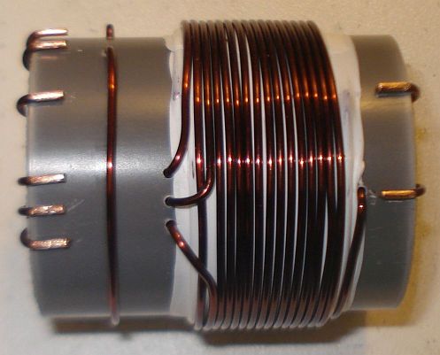
Wind 2 turns of 1mm diameter enameled wire on top of the primary winding and secure the winding in place as shown in the picture below. Notice the winding direction of the wire, as well as it’s position relative to the primary winding. This is the feedback of the transformer, the one that is connected to the collector of the transistor.
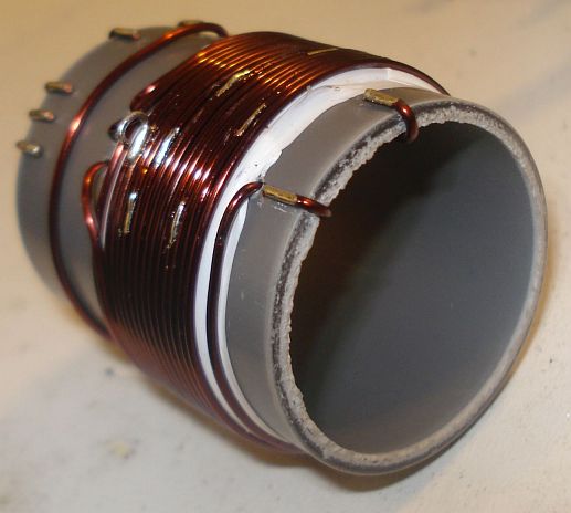
Step 6:
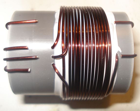
Wind 14 turns of 1mm diameter enameled wire on top of the primary winding, starting from just next to the 2 turns one and secure this winding in place as shown in the picture below. Notice the winding direction of the wire, as well as its position relative to the primary and the 2 turns windings. This is the secondary (output) of the transformer, the one that is connected to the antenna. At this point do not worry about the taps yet.
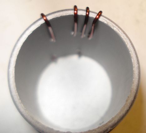
Notice in the picture below, the way the windings are secured in place onto the pipe. The wire ends are passed through the pipe using small holes and then bent towards the ends of the pipe and once more to the surface of the pipe, where the connections will be made.
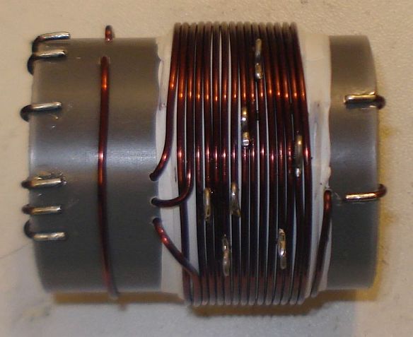
Step 7:
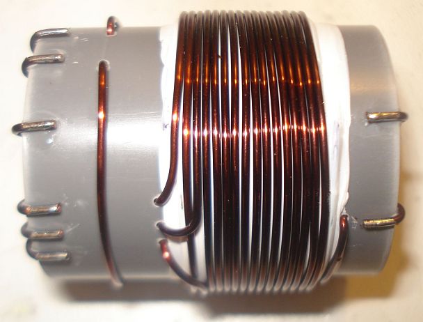
Wind 1 turn of 1mm diameter enameled wire onto the pipe and secure the winding in place as shown in the picture below. Notice the winding position relative to the other windings. This 1 turn winding is placed about 1cm away from the other windings. This is the RF pick up winding, the one that is connected to the incandescent bulb.
Step 8:
Use a sharp cutter (knife) and carefully scrap the enamel of all the windings ends. Do not worry if you cannot scrap the enamel at the bottom side of the wire ends (that touches to the pipe). We just want enough copper exposed to make the connection.
Step 9:
Tin the scrapped wire ends, taking care not to overheat them much.
Step 10:
Now it’s time to make the taps on the secondary winding. Use a sharp cutter (knife) and very carefully scrap the enamel of the wire at the tap points (number of turns). Take much care not to scrap the enamel of the previous and the next turn from each tap point. Do not worry if you just scrap the enamel at the top of the wire (external area). We just want enough copper exposed to make the connection.
Make each tap, a bit offset from the near by taps, like shown in the pictures. This will avoid any short circuits (especially at the 4, 5 and 6 taps) and it will allow for easier connections, especially if alligator clips are used to connect to the taps.
Step 11:
Tin all the tap points, taking care not to overheat them.
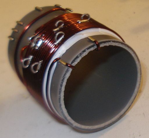
Step 12:
This step is optional and it depends on how you decide to do the connections to the taps. You may solder wires directly to the tap points, but in my case I wanted to use alligator clips, so I did the next: I took a piece of a component lead and soldered it’s one end to each tap point. Then I bent the component lead to U-shape and cut it accordingly. This created nice and rigid tap points for the alligator clip.
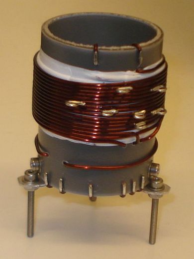
Step 13:
This step is optional and it depends on how you decide to mount the transformer to your enclosure. In my case, I wanted to create three small legs for the mounting. I cut three pieces of aluminum straps and made holes at both their ends. I made three small holes onto the transformer pipe end and mounted the aluminum straps using screws. After mounting them, I shaped the straps to L-shape. Then I used three more screws to mount the transformer to the enclosure.
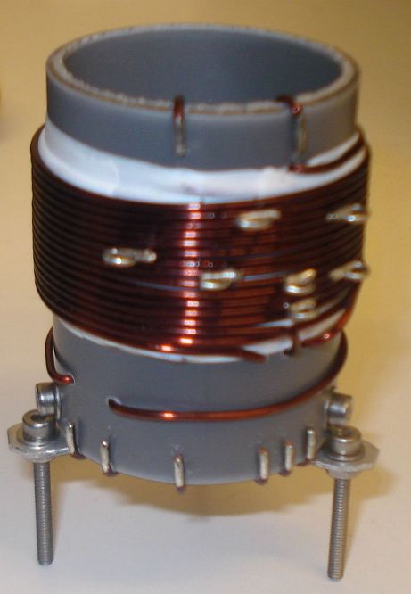
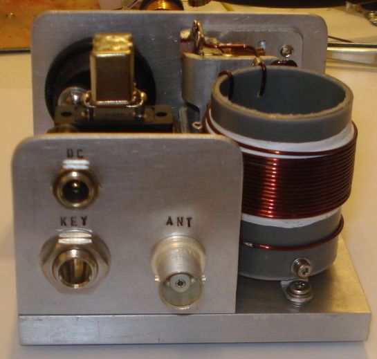
The completed transformer is shown in the pictures above and below. The 6 connection points at the bottom of the pipe, are the low voltage points, whereas the 2 points at the top of the pipe, are the high voltage points.
If you have built the transformer as described, the bottom connections are as follows (from left to right):
Wire end 1, connected to the incandescent bulb
Wire end 2, connected to the incandescent bulb
Wire end 3, connected to the current meter
Wire end 4, connected to the current meter
Wire end 5, connected to the GND (ground)
Wire end 6, connected to the transistor collector
The top connections are as follows (from left to right):
Wire end 1, connected to the 25pF variable capacitor and the Cy fixed.
Wire end 2, is the 14th secondary tap and it is left unconnected, or tapped to the appropriate impedance antenna.
Videos of the EMTX in operation
I have made two small videos of the EMTX in operation.
The first 13.5MB video (right click to download), shows the operation when the transmitter is set for a bit less than 10W of output power.
The second 3.5MB video (right click to download), shows the operation when the transmitter is set for about 5W of output power.
EMTX chirp analysis
Every self-exited power oscillator (and even many multi-stage designs) exhibits some amount of chirp. Chirp is mainly considered as the sudden change in frequency when the power oscillator is keyed down. Apart from chirp, there is also the longer term frequency stability that may be considered. The chirp in the EMTX is surprisingly low, if it is built properly. Hans Summers, G0UPL has performed a chirp analysis on my EMTX (PDF) and the EMTX built by VK3YE and presented on YouTube. Hans, performed the analysis from the video/audio recordings of both transmitters. I sent him two videos, one with the EMTX set for an output power of 10W and one where it is set for 5W. The chirp at worst case (10W) was about 30Hz and at 5W in the order of 10Hz or so. Being so small, the chirp is almost undetectable by the ear and it surely poses no problems when passing the tone through narrow CW filters. This is an amazing accomplishment from a transmitter so simple and so powerful.
EMTX harmonics measurement
Every unfiltered transmitter will excibit harmonics at it’s output. This means that the output waveform has some distortion in comparison to a pure sinewave. Many of the transmitters I have seen, present a very distorted output waveform and absolutely need a LPF if they are to be connected to an antenna. I can’t say that this is true for the EMTX, because surprizingly, it has low distordion, despite the high output power it can achieve. Although a LPF is always a good idea, it is not that much needed on the EMTX. However you have to use one to comply with the regulations.
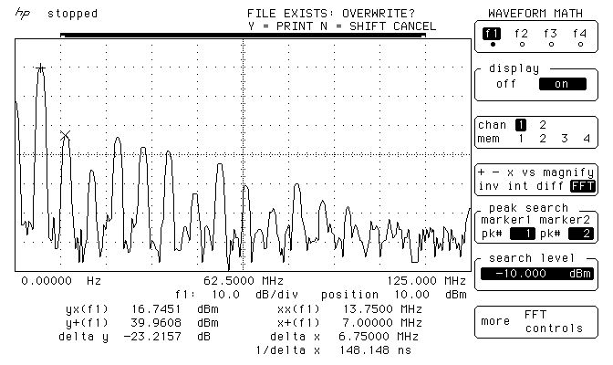
The image above, shows the measurements on the output of the EMTX, when it is set closely to 10W at 50 ohms. The main carrier is exactly at 9.9W and all the harmonics are less than 50mW! Also, the harmonics, do not extend into the VHF region.
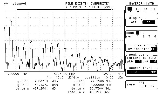
The image below, shows the measurements on the output of the EMTX, when it is set closely to 5W at 50 ohms. The main carrier is exactly at 5.17W and all the harmonics are less than 9.6mW! Again, the harmonics, do not extend into the VHF region.
These small harmonics levels aren’t going to be heard very far at all, compared to the powerful carrier. This means only one thing. A LPF, although a good practice, is not mandatory in this transmitter. But you should better use one so that you comply with the regulations.
Many HAMs use just a watt meter to measure the output of their homebrew transmitters. This is not the proper way of doing it, because the watt meter is a non-selective meter. It will measure both the fundamental carrier and the harmonics, without being able to distinguish them. So in an unfiltered transmitter, or in a transmitter with a simple (often non measured) LPF, this way will give a totally false reading of the output power of the transmitter at the set frequency.
The proper way of accurately measuring the output power of a transmitter and the harmonics levels, is a spectrum analyzer. The FFT available in many modern oscilloscopes, having a dynamic range of approximately 50-55dB, is adequate for this purpose as well. A 50 ohms dummy load must be connected at the transmitter output and then the high impedance probe of the scope, is connected to the output of the transmitter as well. This was the way that the above measurements have been performed.
WebSDR tests
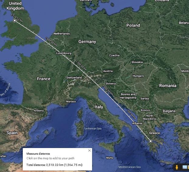
Here are some test transmissions, to determine how far one can get with such a transmitter. I have to say that there is an antenna tuner between the EMTX and my inefficient short dipole (not cut for 40m and not even matched to the coaxial). However I could still cover a distance of more than 2500Km even on the 5W setting.
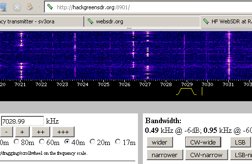
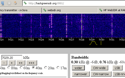
A screenshot of the transmitter signal, as received on a WebSDR 2500Km away and when the EMTX is set for an output power of 10W.
Below, is a picture and an audio recording of the transmitter signal, as received on the same WebSDR and when the EMTX is set for an output power of 5W.
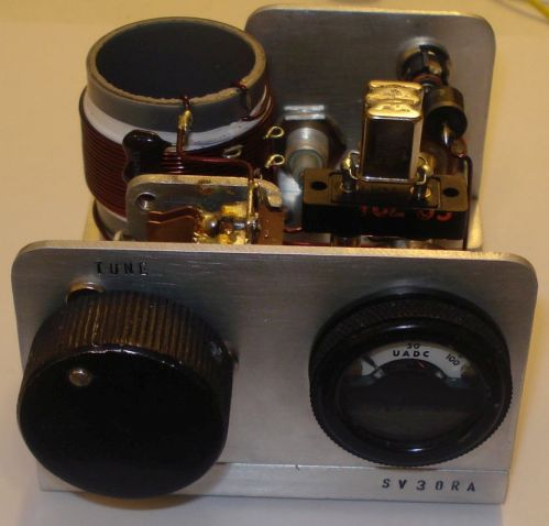
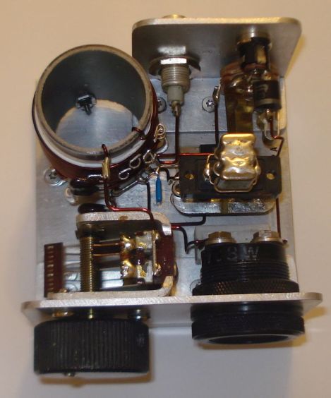
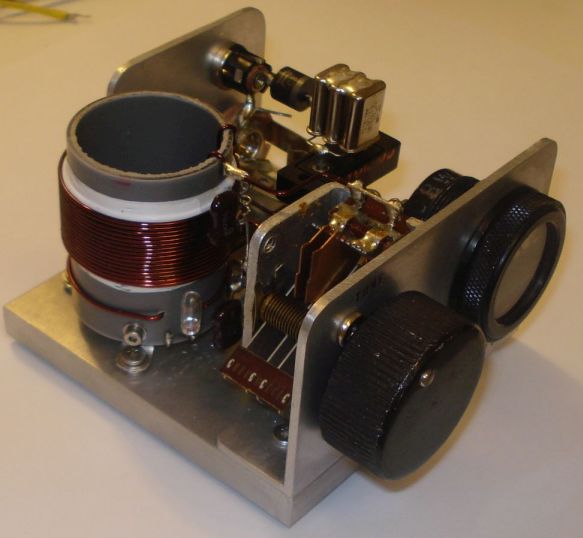
Photos
Pictures of the finished transmitter. You don’t have to build it that nice-looking if you don’t care.
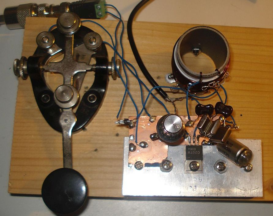
EMTX prototype built on a breadboard. Yes it worked just fine onto a piece of wood.
This is a phenomenal project, Kostas. Thank you so much for sharing it with us. I love the simplicity of this design–truly form following function. With a little patience, anyone could build this transmitter.
Radio Waves: Stories Making Waves in the World of Radio
Because I keep my ear to the waves, as well as receive many tips from others who do the same, I find myself privy to radio-related stories that might interest SWLing Post readers. To that end: Welcome to the SWLing Post’sRadio Waves, a collection of links to interesting stories making waves in the world of radio. Enjoy!
Many thanks to SWLing Post contributors Pete, Bill, Trevor R. and Steve Reardon for the following tips:
The US government is warning that groups could rely on radio equipment as an alternative to social media to plan future criminal activities.
In a stark warning Sunday, the Federal Communications Commission’s enforcement bureau said people coordinating or conducting criminal activity over radio waves are breaking the law.
“The Bureau has become aware of discussions on social media platforms suggesting that certain radio services regulated by the Commission may be an alternative to social media platforms for groups to communicate and coordinate future activities,” the FCC said in its warning Sunday. “Individuals using radios in the Amateur or Personal Radio Services in this manner may be subject to severe penalties, including significant fines, seizure of the offending equipment, and, in some cases, criminal prosecution.”
The FCC licenses certain signals for people to broadcast over radio waves. Those messages are generally protected by the US Constitution’s First Amendment. But the FCC reminded radio licensees and operators that it is prohibited to transmit “communications intended to facilitate a criminal act.” People are also not allowed to encode their messages to obscure their meaning from law enforcement.
The laws governing airwaves apply to amateurs broadcasting with personal ham radios, which can reach long distances. But they also apply to people using Citizens Band (CB) radios commonly used for communication between truckers — or even walkie-talkies.
In the wake of the January 6 Capitol riots, Facebook (FB), Twitter (TWTR) and other mainstream social networks have become more vigilant about policing people who use their platforms to plan or incite attacks. They have booted off several high-profile radicals and thousands of groups and users who the platforms say engage in harmful conspiracy theories and other violence or hate speech.[…]
For over 100 years amateur radio and ARRL — the National Association for Amateur Radio® — have stood for the development of the science and art of communications, public service, and the enhancement of international goodwill. Amateur Radio’s long history and service to the public has solidified the well-earned reputation that “Amateur Radio saves lives.”
Amateur Radio Operators, due to their history of public service, their training, and the requirement that they be licensed by the FCC have earned their status as a component of critical communications infrastructure and as a reliable resource “when all else fails.”
Amateur Radio is about development of communications and responsible public service. Its misuse is inconsistent with its history of service and its statutory charter. ARRL does not support its misuse for purposes inconsistent with these values and purposes.[…]
The doors and windows of the historic Radio Tirana building were removed in the middle of the night during the weekend, while Albanians stayed inside due to heavy rains.
The Villa is a second category monument and was the first media institution in the country. It was built in 1938 by the Kollciu family as a house for two of the brothers. Completely symmetrical in its design and layout, it was built in the Italian neoclassical style that was popular at the time.
It was later seized under the order of King Zog and was the base for Radio Tirana until 1965. It was then used by the Institute of Anthropology and Art until the previous owners took it back. It has since been left to decay and is in a bad state of disrepair.
It stands over four floors including a basement. It features two main entrances, columns, a hallway with marble tiles, wooden framed windows and metallic balustrades.
As it was abandoned, a few members of the Roma community were living there.
Despite it being a cultural monument, the removal of these fixtures signals that demolition could be imminent. It lies just off Rruga Kavajaes and occupies prime Tirana real estate.[…]
There’s no denying Bob Cooke’s passion for radio. The Lower Sackville man used to work in the business back in the mid-1970s and now, it’s likely he has the largest collection of radio gear in Canada. CBC’s Colleen Jones reports.
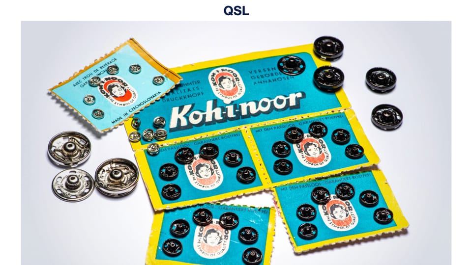
The three letters – QSL – constitute one of the codes originally developed in the days of the telegraph. All codes consisted of three letters beginning with “Q”. Later some of these “Q” codes were adopted by radio-telegraphists and radio listeners. QSL means “contact confirmed” or “reception confirmed”.
The expression “QSL card” or just “QSL” gradually came to be used among radio-amateurs and then more broadly as radio began to develop as a mass medium. Radio stations were keen to know how well and how far away their programmes could be heard and began to send their listeners “QSL cards” in return for reception reports. The card would include letters making up the “call sign” of the station – the system still used in the United States – or the broadcasting company’s logo or some other illustration. The card would also include a text stating the frequency and the transmitter output power, and a confirmation of when the listener heard the station.
Domestic broadcasters do not tend to use QSL cards these days, but their popularity remains among radio stations broadcasting internationally. They are still keen to know how well they can be heard in the parts of the world to which they broadcast. In the era of shortwave broadcasts Radio Prague sent out QSL cards for reception reports received. Today we also send QSL cards to those who listen to us on the internet.
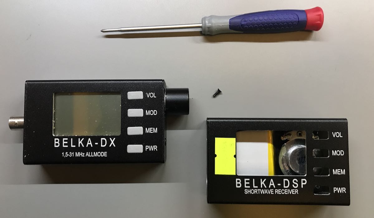
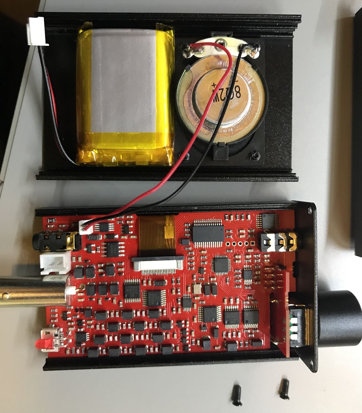
This month, I received my Belka DX speaker option in the post and recently did this very simple install. All it really requires is a small Phillips-Head screwdriver and maybe 10 minutes of time.
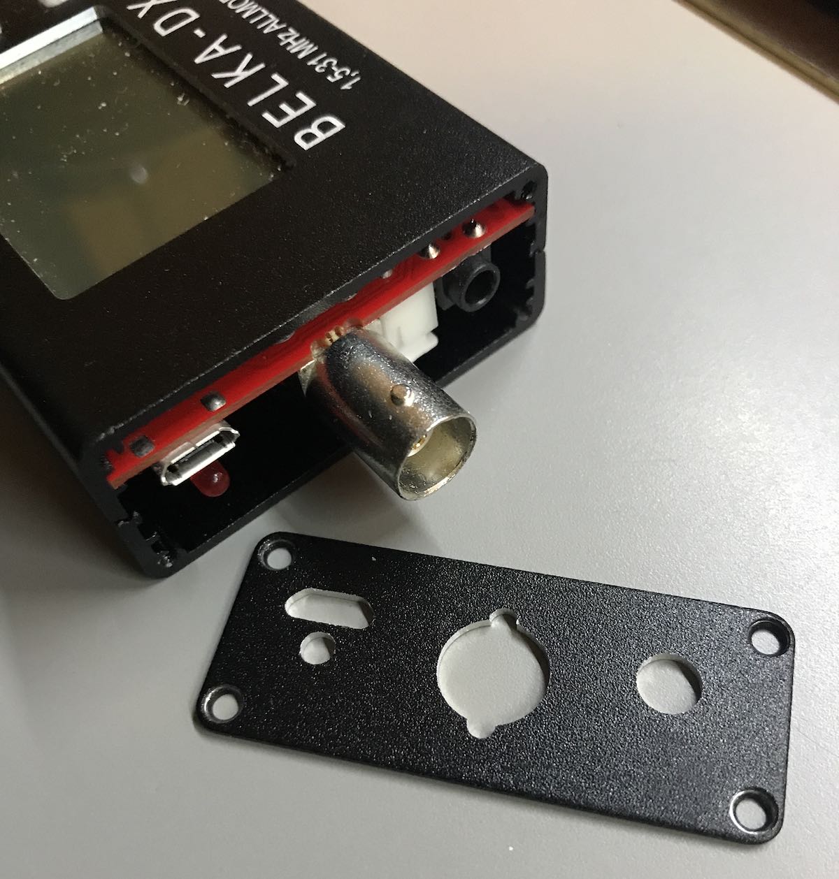
You start by removing the four screws holding on the left side panel. The side panel easily slides off over the BNC connector.
You then remove the bottom two screws of the right side panel. There’s no need to remove the top two screws as you will not remove this panel or the encoder knob. After removing the bottom two screws, carefully pull the bottom panel off.
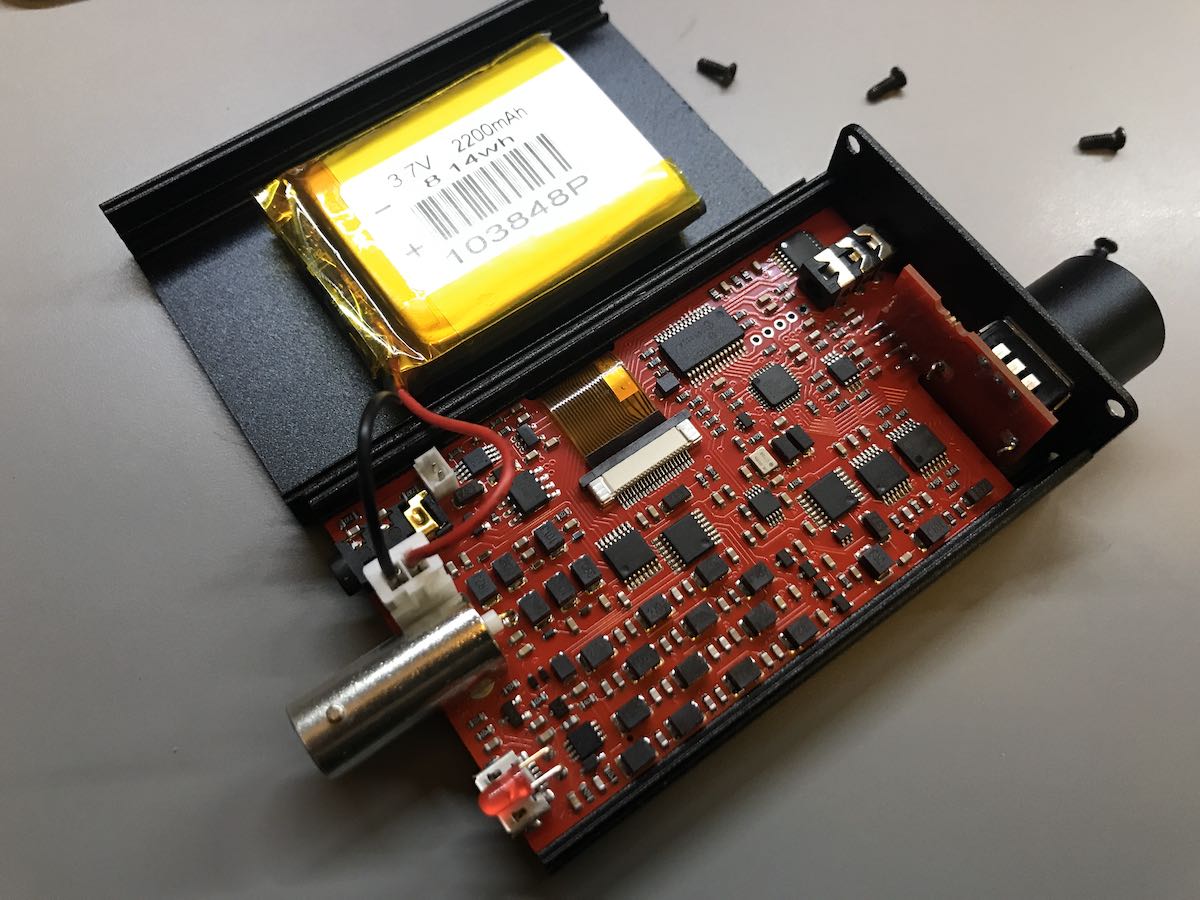
The battery is connected to the Belka-DX DSP board with an end that’s easy to unplug.
Simply unplug the battery, and plug in the new (smaller) battery of the speaker panel in the same position.
The speaker on the new panel needs to be connected, of course. In the photo above, you can see where it attaches to the Belka DX board (next to the headphone port).
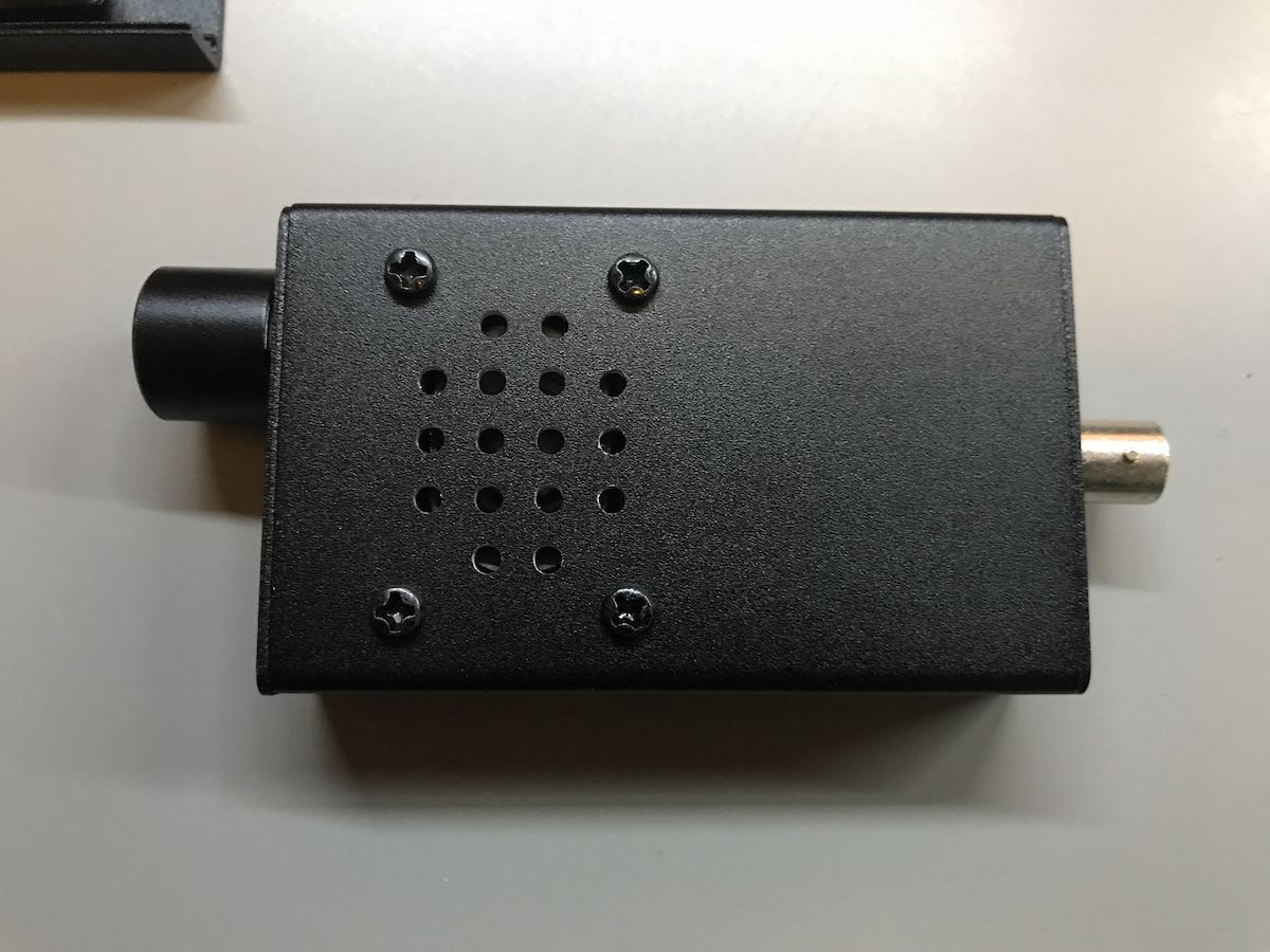
Once you’ve plugged in the new battery and speaker, attach the new bottom panel to the radio, making sure the speaker and battery wires fold in properly. After you’ve put the two right panel screws in, reattached the left panel with four screws and the installation is complete!
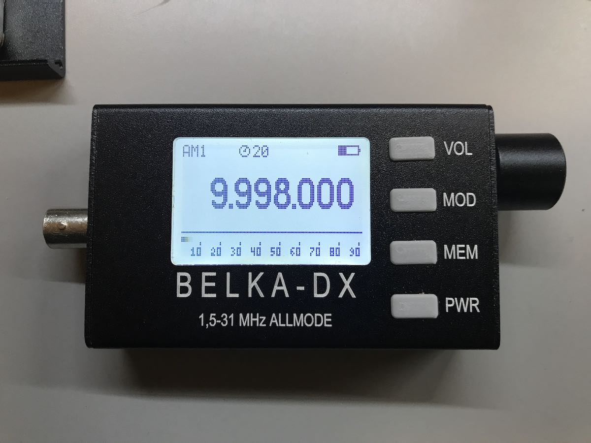
The speaker is quite small, of course, but very functional. I love the fact that I no longer need a set of earphones or external amplified speaker to listen to the Belka DX.
I was concerned that the speaker would be too small to be functional and that the smaller battery in combination would dramatically decrease listening time per charge.
Not the case.
Although I haven’t done a continuos battery longevity test with the volume at a constant moderate level, it will power the radio for extended listening sessions. Of course this teeny internal speaker isn’t going to deliver room-filling audio, but has exceeded my expectations and certainly does the trick!
If you own a Belka-DX DSP receiver, this is a worthy, affordable upgrade. The great thing is, you can always swap out the covers easily if you need the larger battery capacity during travels or DXpeditions.
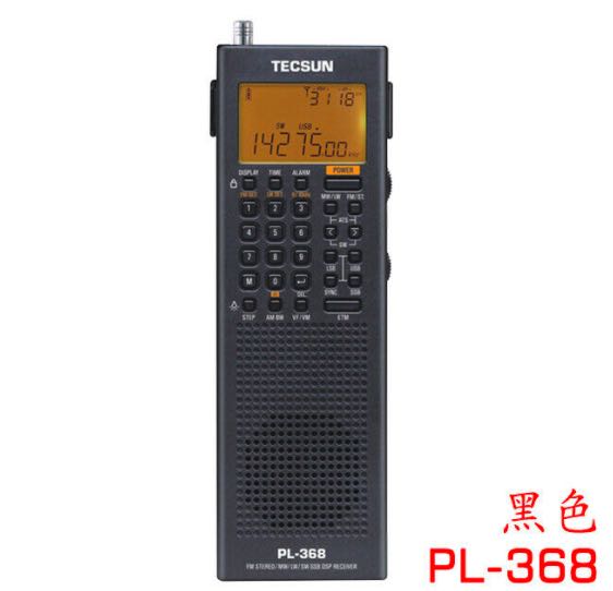
Many thanks to SWLing Post contributors, Tom, Markku, Dave Zantow, and Dan Robinson who note that the Tecsun PL-368 is now available via sellers on eBay.
Fans of the Tecsun PL-360 and PL-365 will be happy that among other things, the PL-368 has sync detection. The price is $88 US plus $3 shipping from China.