Shortwave listening and everything radio including reviews, broadcasting, ham radio, field operation, DXing, maker kits, travel, emergency gear, events, and more
Many thanks to SWLing Post contributor, Richard Cuff, for sharing this column from The Athens News. I’m sure many of us relate to Dennis E. Powell (note this is only an excerpt):
If you lose power at just the right time, it can enrichen your life
This is being written last Monday night.
Several hours after the storms of earlier in the day passed, the sun shining, the birds singing, and all apparently right with the world, the electricity went out. Because there is no cellular telephone service in my part of the county, this necessitated a drive much of the way to Athens to register a report with the power company. The power company’s outage report line is the first entry in my cellular phonebook.
[…]The evening was (and as I write this, is) cool, with a bit of wind passing through the open windows, so there was no panic, as there is when the power disappears in the dead of winter or in the 100-degree summer – both of which I have experienced. But there was no fire to build, no need to think of a reason to drive to town for a few hours in some place air-conditioned.
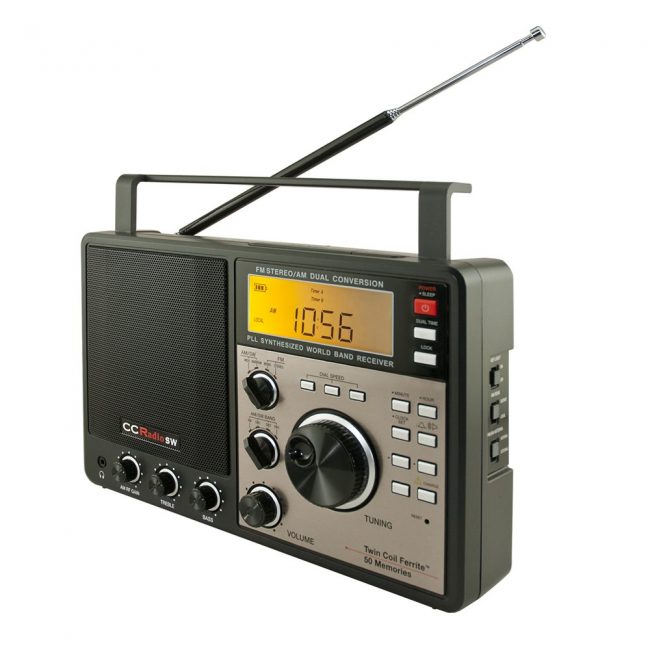
Instead, I remembered that just a few days ago I had pushed the battery-charge button on one of a couple shortwave radios I have around here, this one a decade-old C. Crane CC Radio SW. It has a big speaker and a pleasant sound, though it’s not the sort of radio you get to dig faint signals out of the mud. It is just right for such an evening as this. So I brought it to the living room, extended its built-in antenna, and fired it up.
Shortwave radio is like Forest Gump’s mama’s box of chocolates, and that’s part of its appeal. Poking around the dial I find some Ohio shortwave amateurs putting on a bit of a panel show, passing the mic metaphorically from one to another. Because they are shortwave amateurs, all they talk about was their shortwave equipment.
The power is out all over the neighborhood, so there is not a single static scratch, no 60-Hz whine of interference. And the ionosphere seems stable, no fading in and out of signals.
Heading up the dial, I find a station in accented but easily understood English. I have to listen for a while before I learn that I am listening to Radio Romania International. That broadcast ended, so I retune and find a cranky man and a cranky woman who are discussing how awful things are and how the only thing you can count on is gold.
Moving along, I find an impassioned man with a deep Southern accent. He, too, is discussing how awful things are – and how they soon will be especially awful for those who put their trust in gold or other things of this world.
There is a broadcast from somewhere – from the accents I’d guess the Caribbean or Africa – that features a man and woman talking spiritedly and sweetly about English idioms.
Now I’m listening to the Argentine national shortwave service, which had a talk program in English though they’ve switched to Argentine music.
[…]I do hope the power comes back. Just not tonight. Tomorrow, maybe. Or the next day.
(Note: Just as I set this to email itself eventually to the Athens NEWS, minutes after I was done writing, the power came back on. And it really was a little disappointing.)
An SWLing Post reader recently contacted me with the following question:
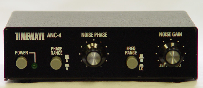
“What devices work well to cancel out local RFI? I’ve been told that both the Timewave ANC-4 and a number of BHI products are all worth considering.”
Unfortunately (or fortunately, for me) I’ve no experience with outboard DSP or noise cancelling devices because I live in such an RFI-free area.
I know this reader already has a Wellbrook Loop, but he’s looking for a way to even increase noise mitigation further at his home listening post.
Post Readers: Can you help guide him? Please comment with your experience. Is a product like the Timewave or BHI the next logical step? If not, what is?
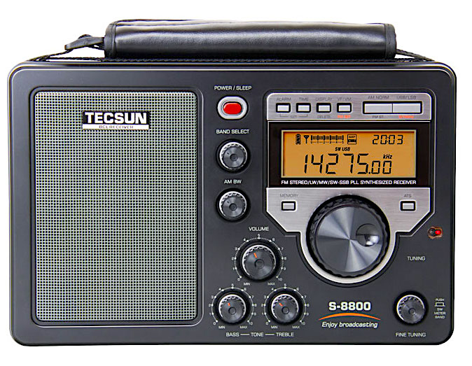
Recently, Tecsun announced and released onto the market the new S-8800 receiver. Thomas Witherspoon has indicated that sensitivity, selectivity and audio fidelity are very good for this new unit.
BUT…..in his post on February 12, 2017, entitled Tecsun S-8800 Update, Thomas discovered that his new S-8800 has a serious fault, one that could potentially drive radio enthusiasts mad! In tuning around the dial, he found the radio has many “birdies”. In the same post, he notes that Bertrand Stehle F6GYY also found birdies on 4 spots in the mediumwave band and 63 frequencies across the entire shortwave spectrum. Not good!
In reading the comments that followed Thomas’ post, I noted that a few writers seemed a little confused about what a birdie is and how it differs from radio frequency interference. Hopefully, the following explanation will shed some light.
The term “birdie” is, I guess, derived from the type of sounds that are emitted from a receiver having this problem. It can take on a variety of forms, like a squealing or whistling sound, or perhaps a warbling sound, or a hash noise, or indeed, even a silent carrier. In a particular radio, a birdie could appear on one or many frequencies across longwave, shortwave, mediumwave or into the VHF spectrum. And it will usually be permanently there on the same frequencies every time.
Occasionally, you will find birdies smack bang on the very frequencies where you might want to do some listening. But, unfortunately you can’t really do anything to get rid of these nuisances because the design faults are in the the receiver itself. You can test to see if what you are listening to is a birdie by simply disconnecting the antenna. If the squealing/whistling/warbling/hash/silent carrier is still there without any antenna, then it’s a birdie – an internally generated carrier by the receiver’s own circuitry.
On Christmas Eve morning, the electricity went off at our house and panic quickly spread among our younger guests.
First, the TV sets went dark. Then, the desktop computers began to die as UPS back up batteries failed. For a while, we were reassured by the sound of familiar alarms, but then suddenly, total silence. Could this be the end times? Is this the onslaught of the apocalypse?
Smart phones were quickly deployed and guests began calling each other from room to room. The panic began to subside when several millennials volunteered communal usage of their wireless data plans. The kingdom would be saved…crisis abated.
[…]As the younger generation huddled around the smart phones with data plans, I began to think of the outage as an opportunity to listen to AM Radio, so I went to my office and dusted off my old RCA SuperRadio III.
I couldn’t remember the last time I replaced the batteries but to my surprise, it came to life with its signature popcorn sound when I pushed its big silver button. “IT’S ALIVE” WOW…the AM band was extraordinarily quiet and responsive.
[…]I scanned across the dial from 610 AM to 1590 AM. All the stations were as clear as a bell. Then, I decided to press my luck. I tuned to KTSA 550 AM in San Antonio and then I moved the dial slightly to the right and heard KLVI 560 AM in Beaumont, Texas. Every station was booming in loud and clear.
I felt like a child with a new toy. I dialed up and down the band, experiencing the clear booming sound of AM Radio without any noise or interference. It was a feast for the senses. It was beautiful.
After a few minutes, one of my daughters walked in and asked about the source of my entertainment. I pointed to my SuperRadio and said joyfully, “listen”. She looked at the big black box and asked “How can you listen with the internet and electricity off?” I responded, “It’s my portable SuperRadio III.” Before I could explain further, she shrugged her shoulders, closed the door and went back upstairs, convinced that her Dad was conducting some sort of high tech experiment.
In a manner of speaking, her assumption was correct. I was listening to AM Radio in a big city without the interference of computers, wireless modems and an overloaded electrical grid. For the first time in my recent memory, the “Senior Radio Band” sounded beautiful. Sadly, my experiment ended with preordained results when the electric power was restored.[…]
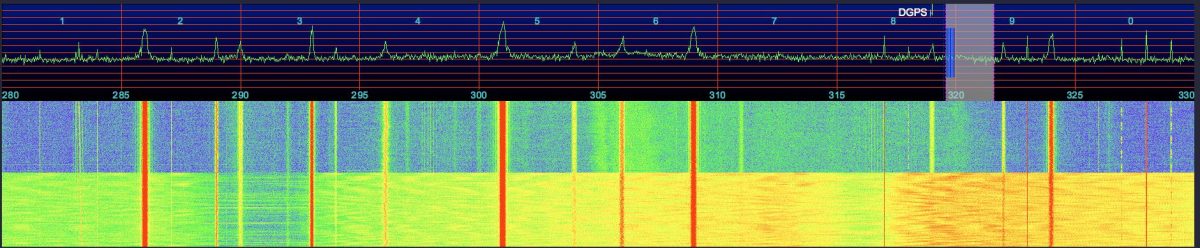
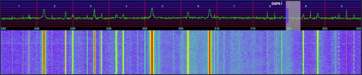
The past few days, I have noticed higher than usual noise levels, generally on the lower frequencies, and particularly on the longwave band, including the 285-325 kHz DGPS band, where I run nightly SDR recordings, to later process the data and decode and detect DX DGPS stations using my Amalgamated DGPS app.
Thinking back to what new electronics devices have been added to the house, two came to mind, a new cable modem, and a new ethernet switch. The switch is up here in the shack, so it seemed to be a likely candidate. The switch is a D-Link DES-1008E 8-Port 10/100 Unmanaged Desktop Switch. It uses a mini USB port for power, using either the included AC adapter, or power from a USB port. When I installed it, I decided to not use the AC adapter, but rather a USB port on my UPS, figuring it was better to not add yet another potentially noisy switching power supply to the mix.
The test was easy, I just unplugged the power to the switch. Sure enough, the noise vanished. Great, the switch is a RFI generator. Or is it? As another test, I plugged it into a port on a USB hub. No noise. Hmm… so it seems that the noise is indeed from the USB port on the UPS. I did not notice any increase in the noise floor when I got the UPS a few months ago, but It’s something I should look into again, just to be sure. The UPS is a CyberPower CP1350PFCLCD.
Here’s a waterfall from the SDR, showing the DGPS band, 280-330 kHz. You can see where I changed the power to the switch from the UPS USB port to the USB hub, the bottom part of the waterfall is when the switch was still powered by the UPS (click to enlarge it):
I still have a noise source just above 305 kHz to hunt down.
Update
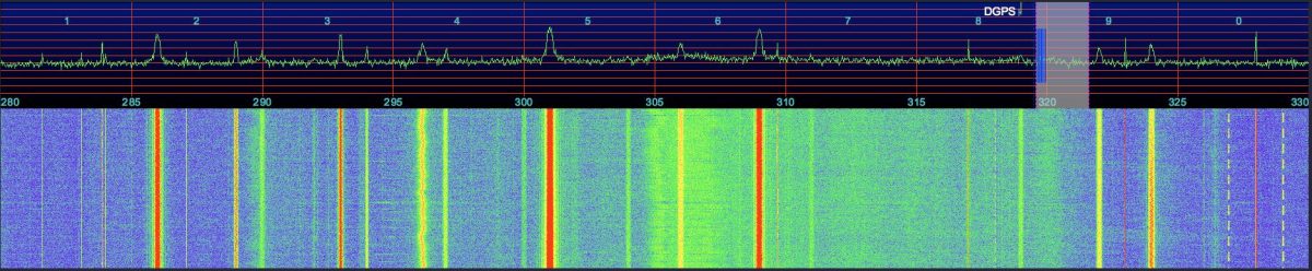
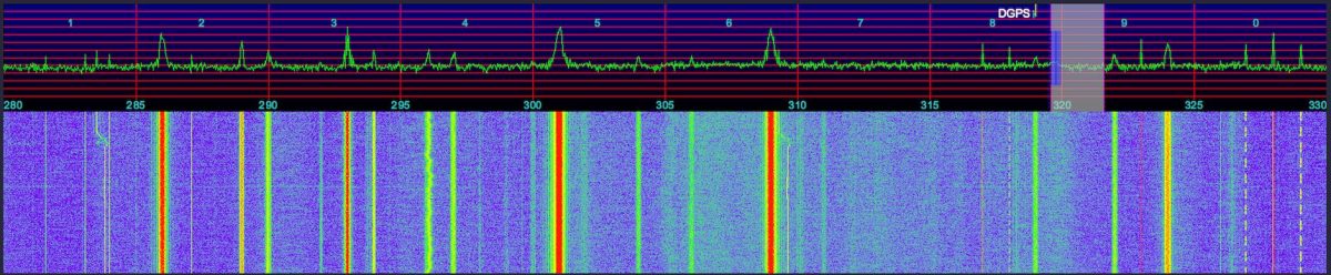
I decided to see what I could do to improve things, and reduce the noise floor.
Here is the baseline, after no longer powering the switch from the UPS:
First, I relocated the AFE822 away from the computer and rats nest of assorted cables behind it, powered from an HTC USB charger:
The squiggly noise around 305 kHz vanished!
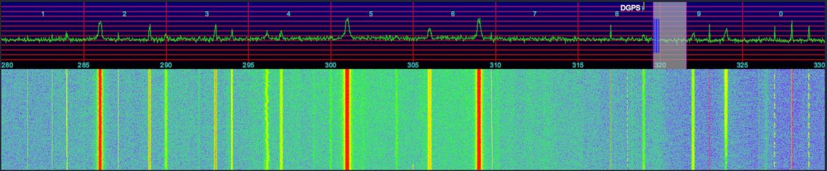
I then switched to an Apple USB charger / power supply, as their products tend to be a bit better made:
Another improvement, the overall noise floor is a bit less now.
But can we do better? I then switched to an older USB hub for power to the AFE822, that I thought might be better filtered:
I then changed to a linear supply plugged directly into the AFE822. I don’t notice any obvious improvement? Maybe it even looks like a little more noise? Difficult to tell. You can see a DGPS station popped up on 304 kHz while I was switching things around, between the last two tests, it was likely Mequon, WI.
Thank you for sharing this, Chris! I find a wideband spectrum/waterfall to be such a useful tool for tracking down sources of noise. Not only can you “see” the noise, but you can measure its bandwidth and identify what portions of the dial it affects.
In a previous guest post, SWLing Post contributor TomL, shared his “Evolving, Morphing, SW Listening Station” where he detailed the many ways he’s trying to fight heavy radio interference at his listening post. The following post is TomL’s update:
More Anti-Noise Ideas
(Continuing the hunt for better reception in a foul RFI environment)
by TomL
I have made the following changes:
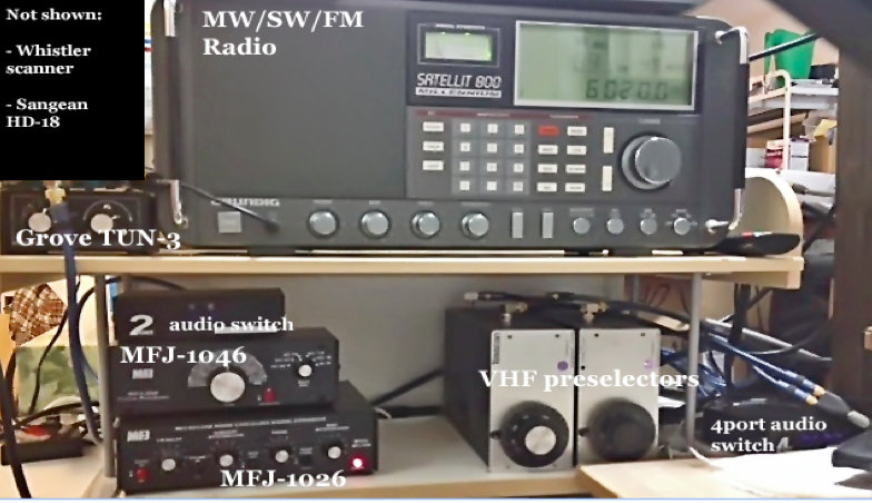
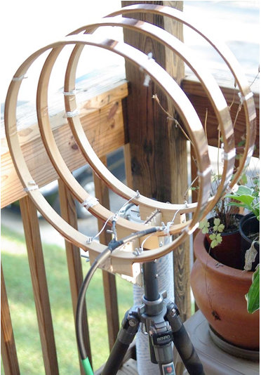
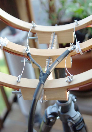
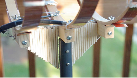
Created a prototype mini-loop based on a crossed-parallel idea from VE1ZAC (Jeff).
Added 2 preselectors, an old Grove TUN-3 connected to the main loop feed and an MFJ-1046 connected to the ground connection of the balun. Both feeds go into the MFJ-1026.
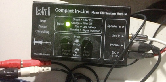
Added a medium wave noise canceling unit that I have not figured out how to use yet. (Quantum Phaser). The MFJ unit does not work on medium wave without modification.
Purchased from eBay a used Grundig Satellit 800, a somewhat more robust fixed-station receiver to replace my aging Sony ICF-2010.
Other non-related (not shown): Whistler digital scanner + UHF over-the-air TV + FM broadcasts + an AM/FM HD digital radio + high pass filters from MiniCircuits.com – (audio from all these sources is passed to an existing high fidelity stereo power amp and NHT Super One speakers on the computer desk for near-field monitoring). Associated antennas are also hidden on the outside deck (shhhhh!).
Large charge card balance!!
So, here are some pics for the crossed-parallel loop. VE1ZAC web site has all the references if you want to explore further or google him. Mine is purely a prototype and not finished. And should eventually be placed on a rotor (but how to keep my Nazi-like condo association from finding out?!?!?!?).
It is three 14 inch quilters hoops from Joann Stores plus some 1-inch copper strips cut from a small 2 meter roll of thin copper from eBay. Then, it is wired in parallel with silver-plated aviation wire on each side with a feed in the middle. Not an optimal placement of the feed, (should go straight down along the pipe). Will fix things up whenever I get some more time.
Seems to be an efficient way to prototype small loops. It is now mounted on a short ¾” inside diameter PVC pipe into a cheap plastic sand-filled deck-umbrella stand. Loops are light and somewhat flimsy, so I mounted the three loops on a plastic triangle ruler and dowel sticks glued to the sides for some extra strength. Good enough for now.
The EF-SWL balun is also in an experimental configuration. Since I read somewhere that loop antennas have a very low impedance at the feed point (like, 10 ohms or lower), I thought I might try a balun that is meant to lower the impedance and mount it backwards. I don’t have a picture of it but the SO-239 output is facing the loop and the screw terminals are facing the direction of the radio. My feeble brain thinks since it is a passive device of coils on ferrite, it should work bidirectionally for receive only applications like this. It seems to work but I have the excuse that I really don’t know what I am doing! 🙂
BHI unit in action.
The BHI DSP filter is useful in some circumstances but I find it fatiguing to listen to. The audio from the Sattelit 800 is so nice, I mostly like it without the DSP. The DSP narrows the bandwidth significantly, somewhere around 4 kHz or less from my hearing. I like that the Grundig has two tone controls. And it also has a stable SSB and on very strong signals with clear audio, I like to listen with SSB lower or upper sideband. But the DSP is useful at times for hash-like noisy signals; it is not quite as good on buzzing noise and I wish the Satellit 800 had a noise blanker, but that would have been a more costly purchase, like a Drake R8A.
So, in a nutshell, I have a discovery about noise here: it is all around me and ubiquitous, like the air I breathe!
I find it hard to null and also worry about peaking a station signal at the same time. However, I do have a lower noise floor with the experimental loop sitting outdoors, especially on medium wave (the Wellbrook amp + loop works great on the lower frequencies – am able to get eight different medium wave stations carrying Major League Baseball games at night – it would be nine to get WFAN for the New York Mets but the local Chicago Cubs station covers the adjacent frequency with horrible digital hash! ***Bleeping*** digital junk!).
Also, the signal level is noticeably lower using the loop. Then, add in the effect of the MFJ Noise Canceling unit, the usable signal gets even weaker.
The bottom line is, I can now finally enjoy listening to many SW broadcasts, BUT only the strongest signals. Anything else is still hopelessly lost in the noise. So, gains are limited.
On the other hand, and something else I learned by doing is that, any 1 or 2 dB signal/noise ratio improvement will help with the final audio output in the end product. Using low-noise amps, loops, noise canceler, preselectors, grounded connections, ground isolators at the input of every receiver, high quality stereo amplifier and speakers, tone controls, SSB vs. AM Sync, weird antenna configurations, etc, etc. It all helps in the end to some degree.
Tinkering is an art that involves a lot of thinking/doing iterations! And high quality parts must be used all along the chain or it could degrade the signal.
Below are some audio samples, not very well recorded, but can give some idea of the incremental improvement with each enhancement (turn up the volume). NOTE: other people may get better or worse results depending upon individual situations, type of antennas used, etc, etc.
Recording 1: R. Marti. First 10 seconds an indoor antenna with no noise reduction, second 10 seconds the outdoor loop without the MFJ-1026, the third 10 seconds with the MFJ-1026, then switched off and on to hear the difference.
Recording 2: R. Marti. MFJ -1026 is ON. Last 15 seconds is SSB, very thin sounding. Really only good for strongest signals. I liked the AM Sync better (Satellit 800 is really a Drake SW8 in disguise with a quality AM Sync). But, SSB can sound excellent with very clear voices with a steady and strong signal (The Satellit 800 does NOT have IF-shift or a BFO to fine tune an SSB reception, so the station must be exactly transmitting on the kHz mark, which most are nowadays).
Recording 3: R. Marti. MFJ-1026 is ON. Last 20 seconds you hear me switch in the two audio switches and the BHI DSP is on its lowest setting. Narrower and clearer with some reduction of background noise. I find I only like going up to about 4 on the DSP dial, after that the audio fidelity starts getting more choppy with digital artifacts that sound like dripping water. I tend to like higher fidelity. One nice thing about the BHI DSP is a faux-stereo that helps a little with voice intelligibility by helping the brain naturally filter the noise. Faux-stereo is ON even when the noise reduction circuit is manually turned off (power must be on and bandwidth still sounds narrowed).
Recording 4: R. Nacional Brazilia. First without MFJ-1026, then ON, then OFF, then ON, then with the BHI kicked for the last 20 seconds.
Recording 5: Greece. Switching the MFJ-1026 on and off every 5 seconds. In this particular case, the signal was weak and fading a lot. The MFJ OFF was also weaker than with it turned ON. That is interesting behavior, usually it is opposite. It pays to play with the settings a little. At other times, and less frequently, the MFJ unit turned OFF sometimes sounds better than with it ON and tuned for less noise. Go figure!
After all the tweaking is done, and I cannot get any more performance out of this, I will probably have to move to a nice, quiet neighborhood and setup a nice antenna farm!!
In the meantime, I do enjoy listening to the stronger stations from North America, Cuba, Brazil, Europe, and Australia with less noise than before.
73’s
TomL from NOIZEY Illinoiz
Once again, Tom, thanks for sharing your RFI elimination journey!
I love how you take on this noisy problem by experimenting and seeing it more as a challenge than an obstacle to enjoying your hobby. Great job!
Many thanks to SWLing Post contributor, DanH, who writes:
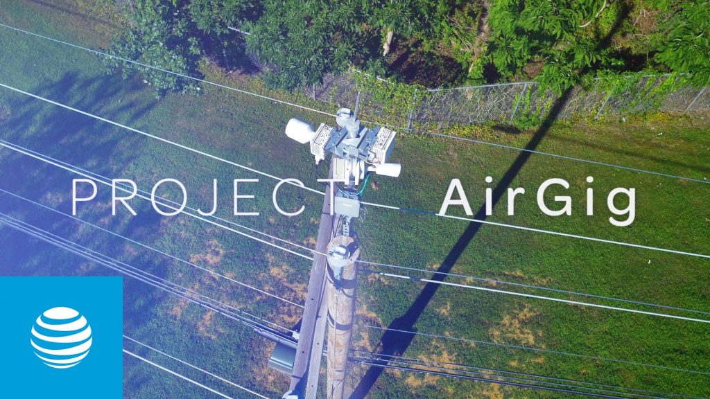
I read this news item today. AT&T has a new approach to broadband over power lines called AirGig. Supposedly, this technology will avoid RFI issues encountered with previous BPL technologies. This shouldn’t be an issue in my neighborhood where power lines are underground. Underground utilities still have RFI issues. My next door neighbor’s AT&T high speed internet swamps out all nearly all shortwave signals below 4.7 MHz within radius of 30 feet from the connection box.