Many thanks to SWLing Post contributor, Don Moore–noted author, traveler, and DXer–for the following guest post series:
Don Moore’s Photo Album
by Don Moore
Introduction
When I discovered DXing over fifty years ago I also discovered the world. Through my ears I traveled to other countries and explored other cultures. But DXing has also literally taken me places. My early interest in Latin American DXing developed into a broader interest in Latin America. That led to me joining the Peace Corps after college and working three years in Honduras. That experience furthered my interest in Latin America and I have continued to travel in the region whenever possible. For me DXing and travel were always intertwined. I’m one of a handful of hobbyists who took DXing beyond just listening and went knocking on broadcasters’ doors to visit the distant stations I heard. My ex-wife dubbed this ‘door-to-door DXing.’
To date I’ve visited over 150 radio stations in thirteen countries. A few were medium-wave or FM only, but I was always most interested in visiting broadcasters that used shortwave, either at the time of my visit or a few years before. As my station visits were primarily made in the 1980s and 1990s, almost all of the stations are long-gone from the shortwave bands. However, many are still around on medium wave and FM and often also via streaming on the Internet. As much as I miss the magic of shortwave I know that these stations reach more listeners today via streaming than they ever did with their low-powered shortwave transmitters. Honestly, I sometimes enjoy tuning them in without the fading and static of shortwave. But the memories of what shortwave once was are still there.
Photos also bring back memories. I took dozens of pictures on my station visits and enjoy scrolling through them now and then. You may have seen some of them. Many of my photos were printed with articles I wrote for various DX publications and I’ve done a few slide-shows at DX get-togethers over the years.
In this series of columns I want to share my old photos once again. If you’ve been DXing as long as I have maybe they’ll bring back memories of what you once heard. And if you haven’t been around that long you will have a better understanding of the good old days we oldtimers talk about.
Ecos Del Torbes
There is no better place to start this journey than with Ecos del Torbes. Using ten kilowatts on 4980 kHz, this Venezuelan broadcaster was possibly the most consistent station in the sixty-meter band throughout the 1970s, 80s, and 90s. If you were DXing the tropical bands during those years you surely logged them a few times. If you were lucky you may even have heard their one kilowatt signal on 9640 kHz. They were a very good verifier and for many DXers Ecos del Torbes was among the first Latin American stations QSLed.
Just after Christmas in 1994, my then-wife, four-year-old daughter, and I flew to Mérida in western Venezuela for a family vacation. For ten days we had a great time in this Andean city and then Theresa and Rebecca returned to Iowa while I stayed another week to visit radio stations. I was also getting paid by the Voice of America to research and write a study on the media scene in Andean Venezuela. The now very-out-of-date report can be read at my Patepluma Radio website (which hasn’t been changed in over twenty years and is in need of a facelift).
In that week I visited fifteen radio stations in six towns and cities and Ecos del Torbes was the highlight. I arrived at their doorstep unannounced but was immediately treated as an important guest. I was given a great tour and even got to sit in on a live newscast to see the famous Venezuelan doorbell being used live. I was there about ninety minutes and then walked a block up the street to sister station Radio Táchira. Their facilities were smaller but that’s where the technical offices were and Chief Engineer Ivan Escobar had been told to expect me. Ivan gave me a tour and invited me to visit the Ecos del Torbes transmitter site with him in the afternoon. On the way we stopped by his house where his wife had lunch waiting for us. Visiting Ecos del Torbes was not just the highlight of this trip but ranks as one of my all-time favorite station visits. These pictures bring back many good memories.
Photos
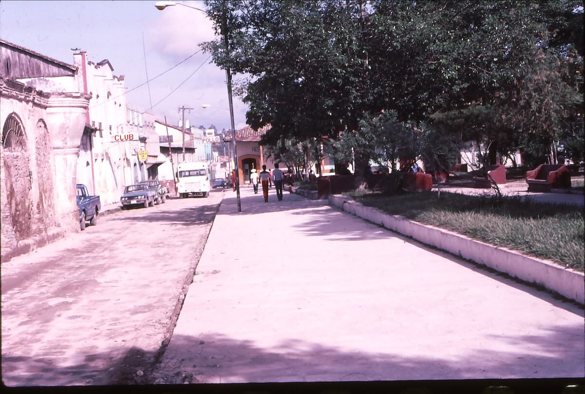
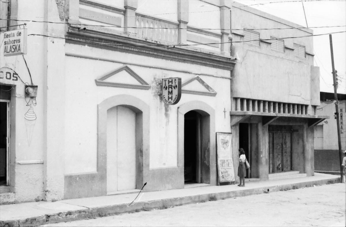
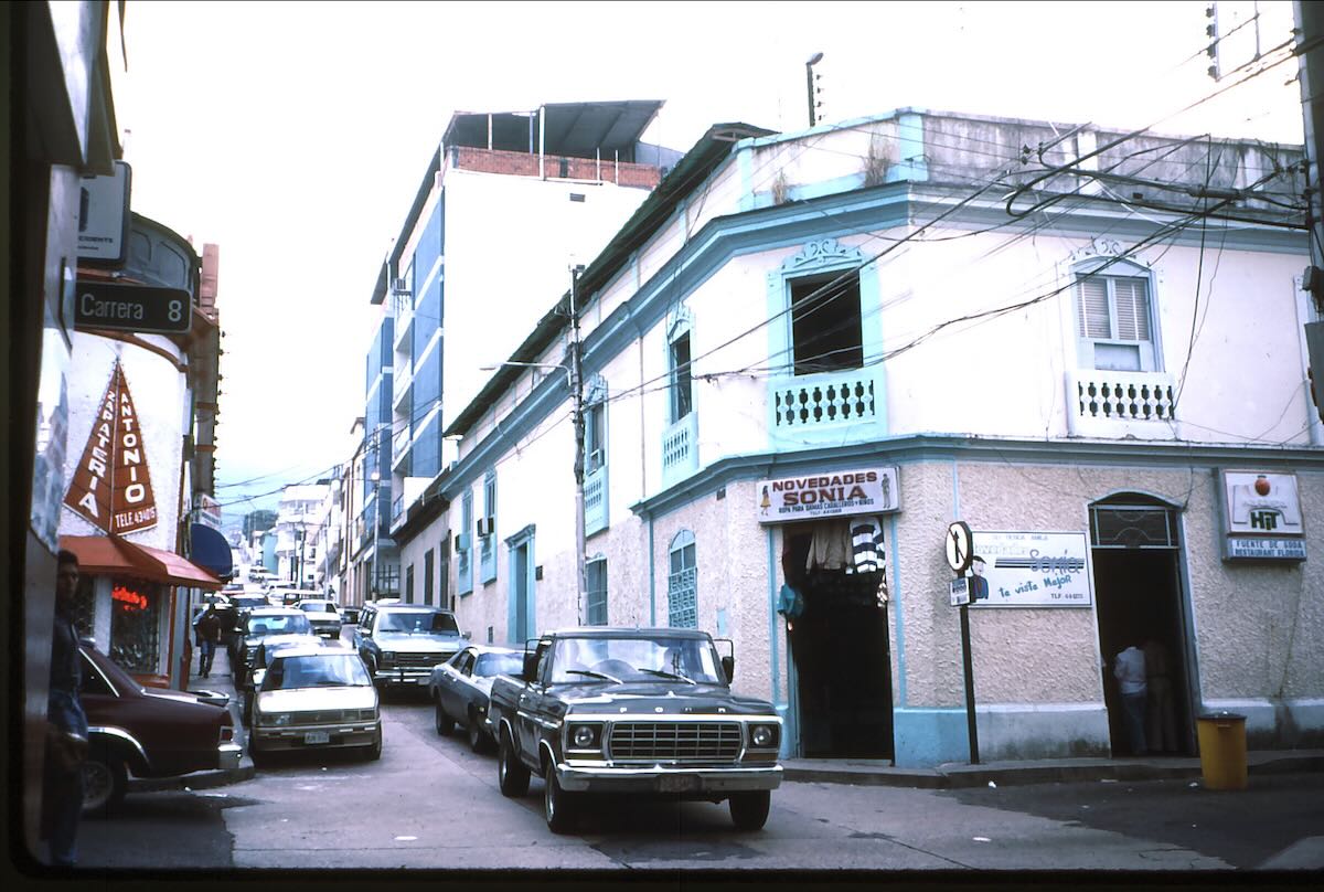
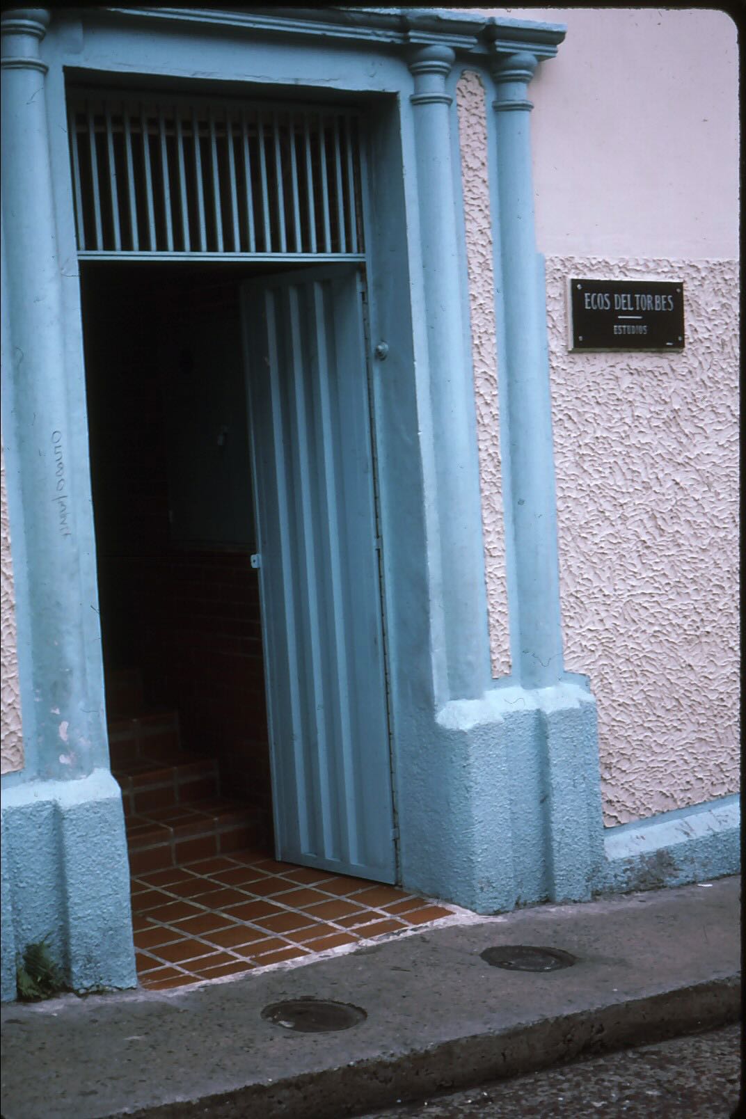
Ecos del Torbes was located in the second floor of this building in downtown San Cristóbal. The entrance was the door on the side.
The small plaque next to the door was easy to miss. I walked right by the first time.
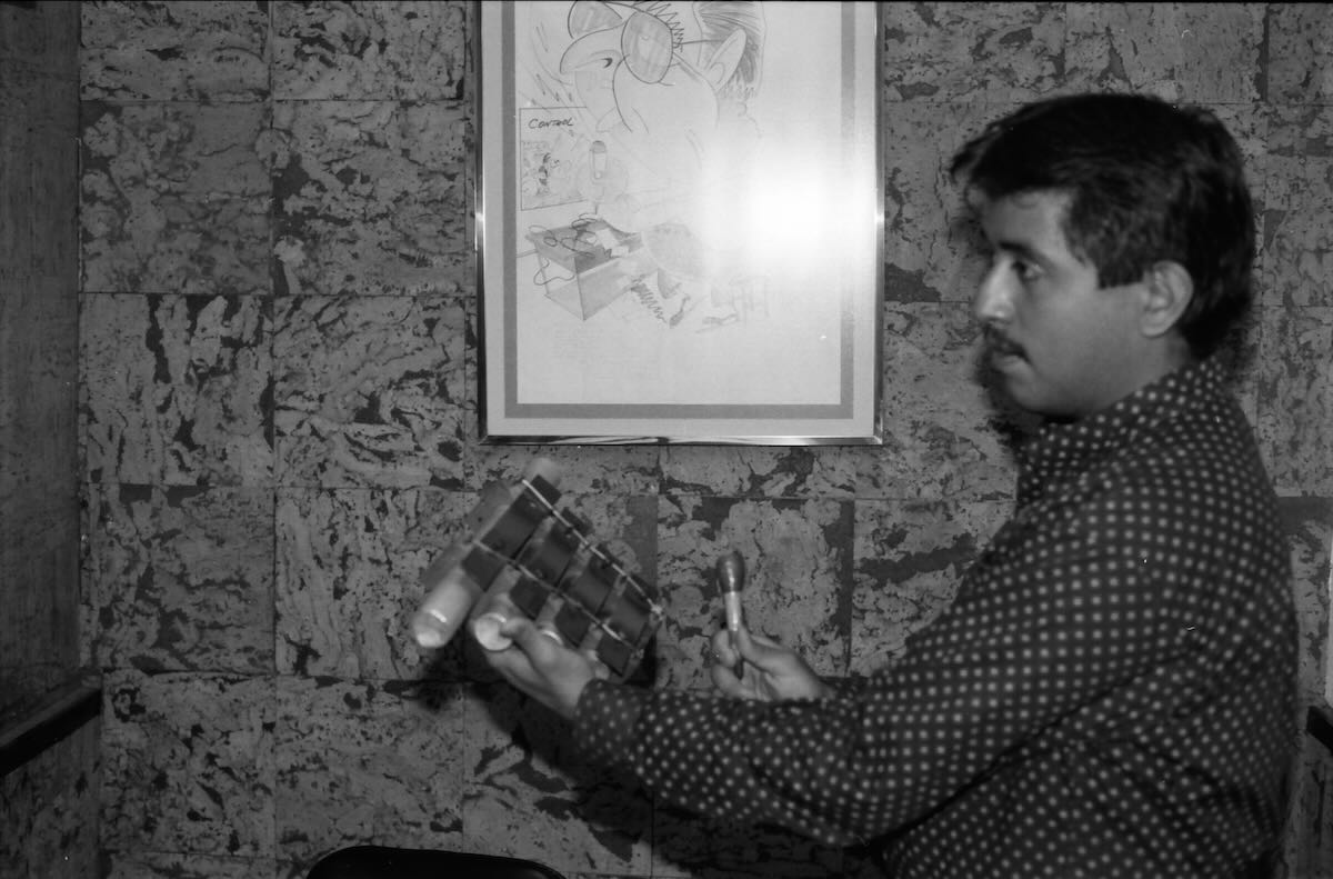
Edgar Fabala of the news department showed me around. Here he demonstrates the mini-xylophones that Venezuelan stations used to make the distinctive ‘doorbell’ sound that separated items in the news reports.
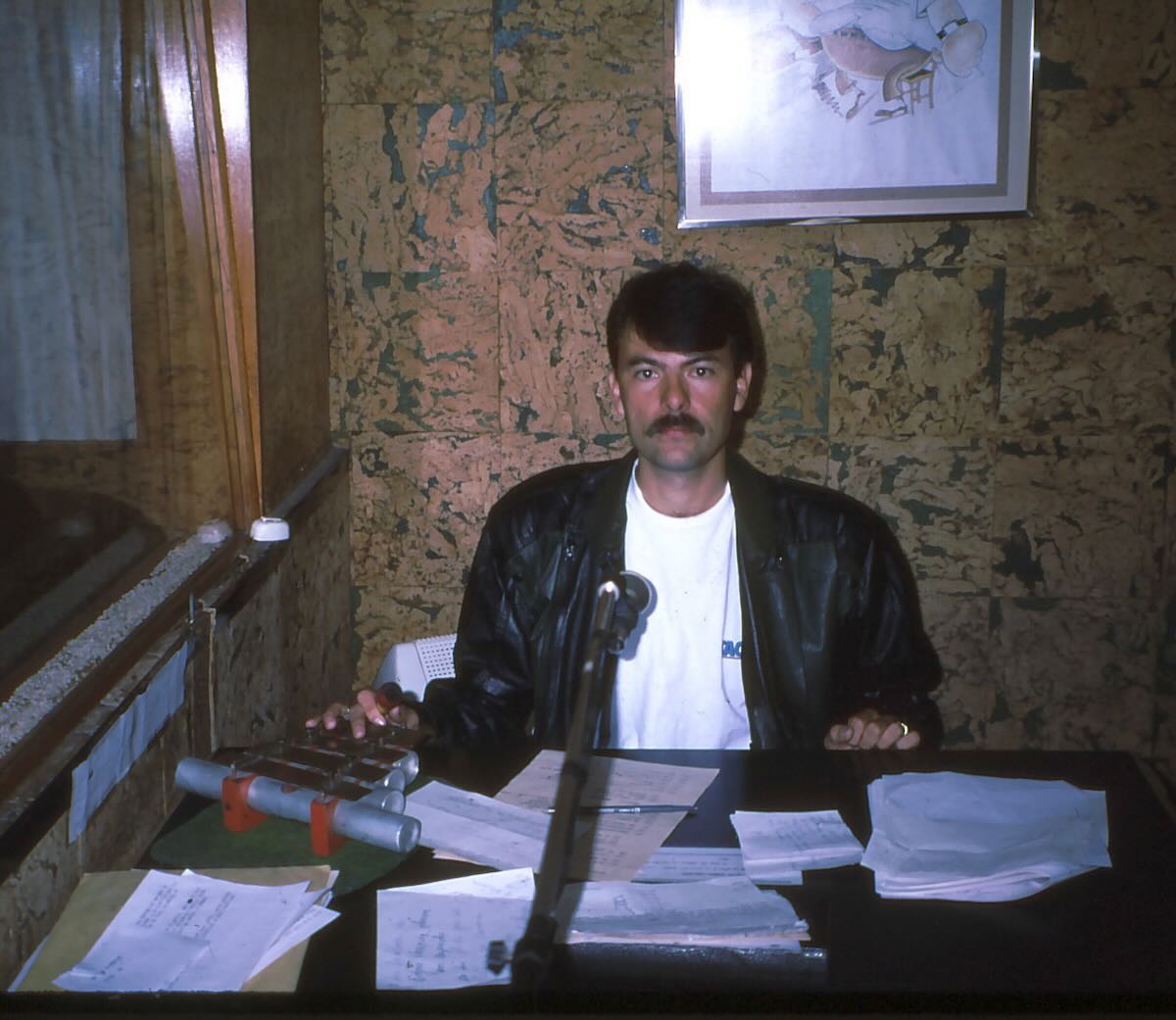
Announcer in the studio preparing to read the news.
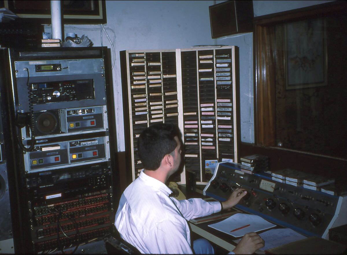
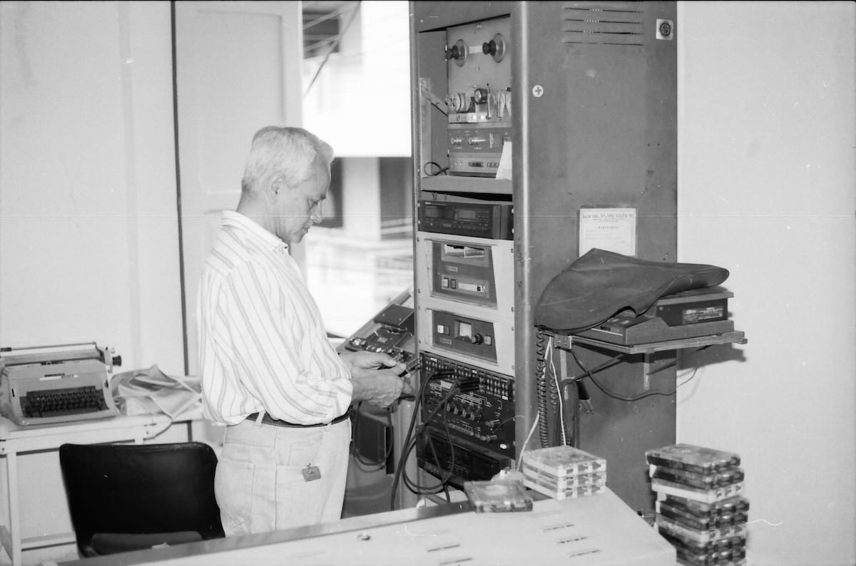
The adjoining control room.
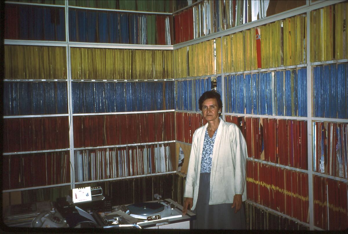
Ecos del Torbes had one of the largest record libraries in Venezuela. The LPs were color-coded by type.
Julio Achila was a control room operator who had worked at the station since it opened in 1947.
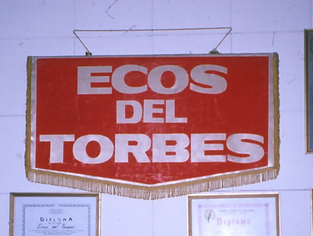
This pennant was considerably larger than the ones sent to DXers.
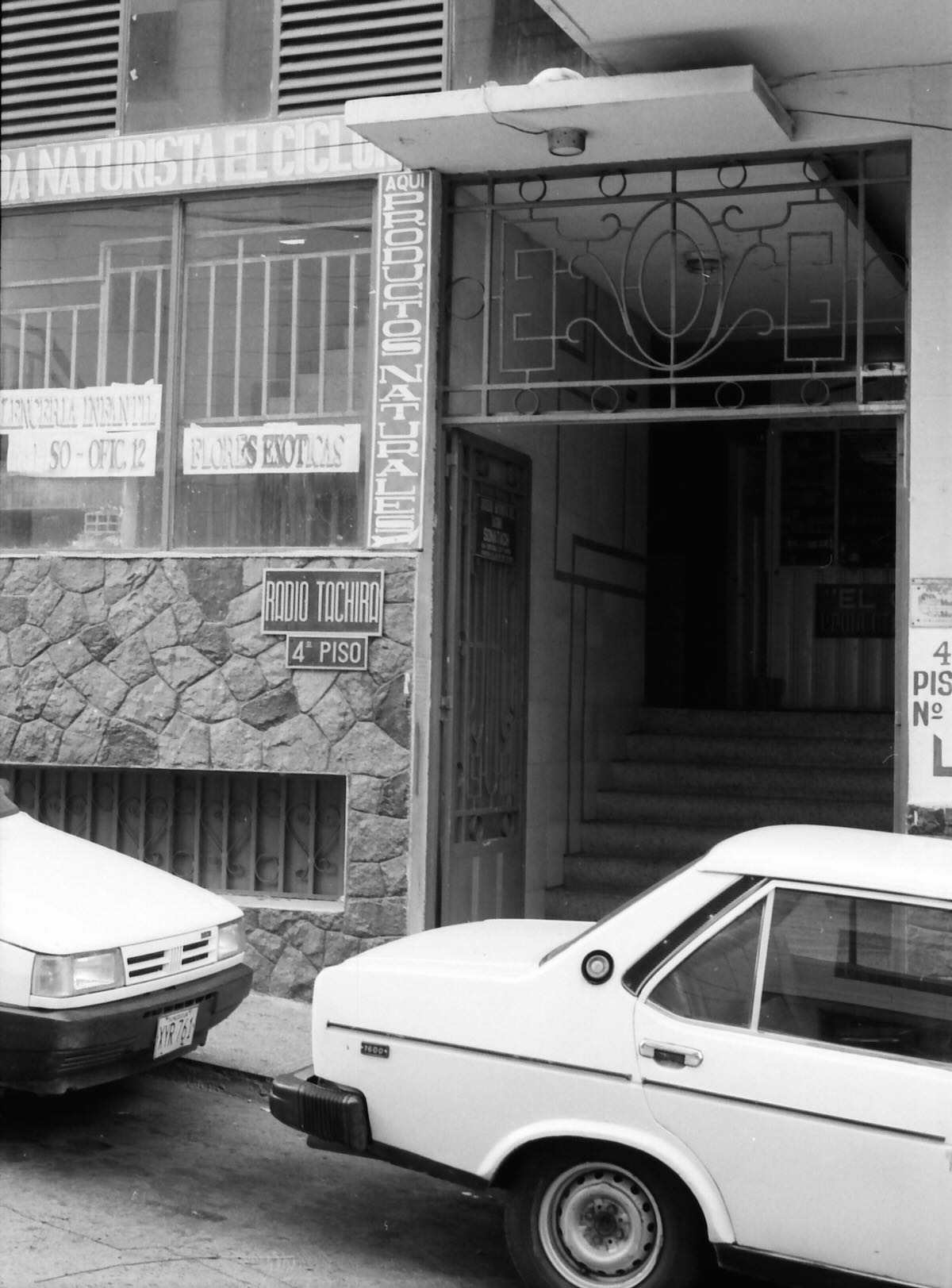
Sister station Radio Táchira was located a block up the street on the fourth floor of this building.
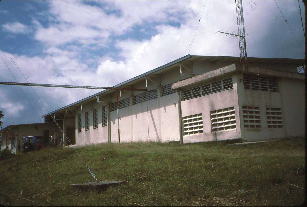
The Ecos del Torbes transmitter building.
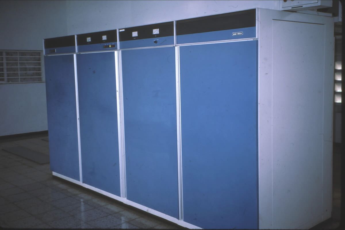
The 50 kilowatt medium wave transmitter on 780 kHz.
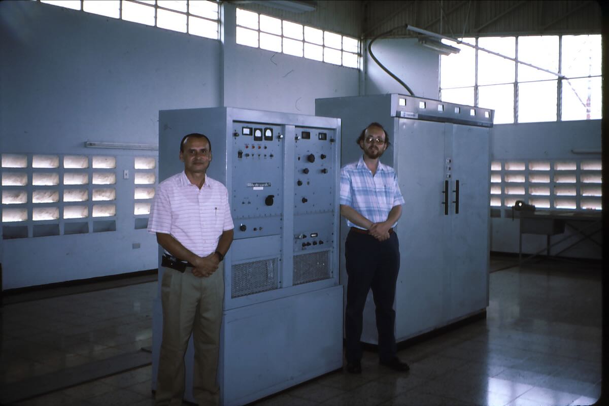
Chief Engineer Ivan Escobar and Don Moore next to the 31 meter transmitter. The larger transmitter was for the well-heard 4980 kHz frequency.
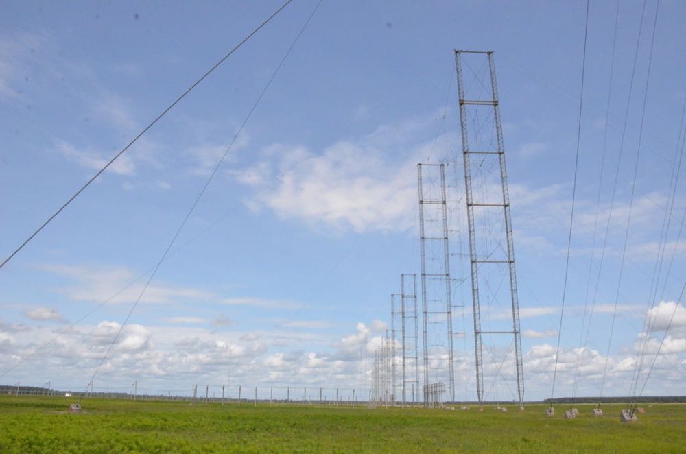
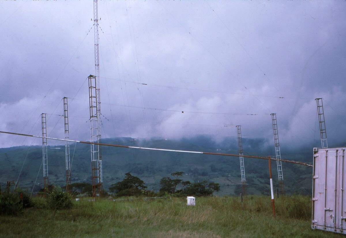
The antenna array used for 4980 kHz. The medium wave tower is in the background.
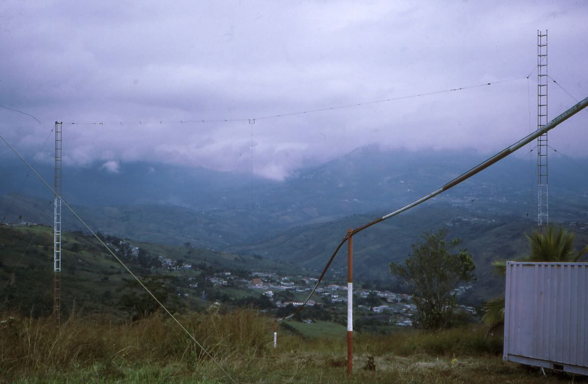
Dipole antenna used for 9640 kHz.
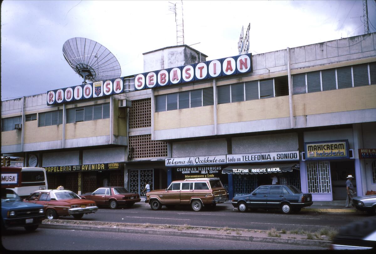
San Cristóbal once had a third broadcaster on shortwave. Radio San Sebastian used 6070 kHz in the early 1970s. (They were not affiliated with Ecos del Torbes).
That was nearly three decades ago and a lot has changed. Ecos del Torbes and Radio Táchira have been gone from shortwave for over twenty years.
In 1995 Ecos del Torbes was at the corner of Calle 9 and Carrera 8, the same address as when I first QSLed them in 1972. Sometime since my visit they moved an outer neighborhood about two kilometers to the east. To find the new offices locate San Cristóbal on Google maps and then search for “Grupo Radial Gonzalez Lovera”. The transmitter site is still where I visited it and can be seen by plugging the coordinates “7.7885, -72.2725” into Google maps and switching to satellite view. (Ignore the picture that pops up to the side. That’s not it.) Zooming in, the medium wave tower is clearly visible but there are no signs of the old shortwave antennas. I suspect they were sold for scrap years ago. I never have found out where the Radio Táchira transmitter site was.
I’d love to go back to Venezuela someday and see some of the other cities that I used to listen to, such as Barquisimeto, Valencia, El Tigre, and Sucre. Unfortunately the political and economic situation there doesn’t look good and it doesn’t look as if it will improve any time soon. But when it does, I’ll be back.
Click here to check out all of Don Moore’s Photo Album columns. Each new article will appear on the SWLing Post home page/feed and in this link.

 Don Moore’s Photo Album: Santa Bárbara, Honduras