Shortwave listening and everything radio including reviews, broadcasting, ham radio, field operation, DXing, maker kits, travel, emergency gear, events, and more
How well could the IC-705 serve shortwave listeners and DXers?
Keeping in mind that the IC-705 is not yet in production, we can only go by the features and few specifications Icom has revealed so far.
Since the IC-705 is a general coverage receiver with a frequency range from 0.5 to 148 MHz, it covers all of the shortwave bands and more.
We also know the IC-705 is based on the same direct-sampling architecture as the excellent IC-7300(click here for our review), thus I expect the IC-705 will sport a capable receiver.
Icom’s other direct-sampling radios have excellent sensitivity and selectivity, so I assume the IC-705 could as well. I would also hope that, like the IC-7300, the AM bandwidth could be widened for full-fidelity AM audio–this has been one of the few criticisms I’ve had using the Elecraft KX3 and KX2 for shortwave listening.
The IC-705 sports other features that could make it an outstanding package for for DXers:
It has built-in audio recording to a MicroSD card. (Woo hoo!)
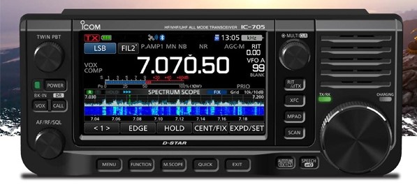
It has a useful, full-color, configurable spectrum and waterfall display
It uses the same BP-272 Li-ion Battery pack as the ID-51 and ID-31 series handy talkies. In receive-only, I would expect long battery-powered listening sessions. Of course, you can also plug in an external 13.8 V battery to increase off-grid listening time.
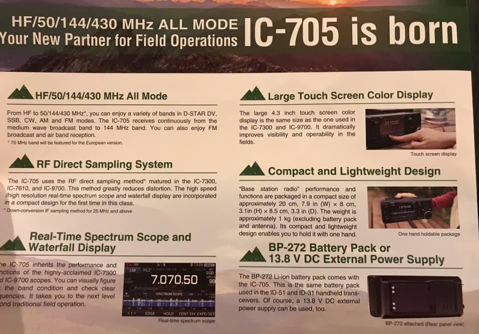
It’s incredibly portable and lightweight
In short, the IC-705 has all of the makings of a fully self-contained shortwave listening station–a grab-and-go DXpedition-grade rig. The IC-705 even has an (optional) custom Icom backpack!
The Icom LC-192 backpack (Source: Universal Radio)
Let’s just hope the IC-705 performs as well as its larger siblings and that its price is competitive.
Again, I plan to review the IC-705 once it’s released and in production. Both pricing and shipping are yet to be announced. Follow the tag IC-705 for updates.
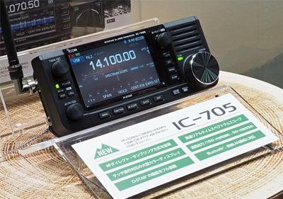
This weekend at Tokyo’s Ham Fair 2019, Icom announced an innovative transceiver to their line-up: the Icom IC-705 QRP transceiver.
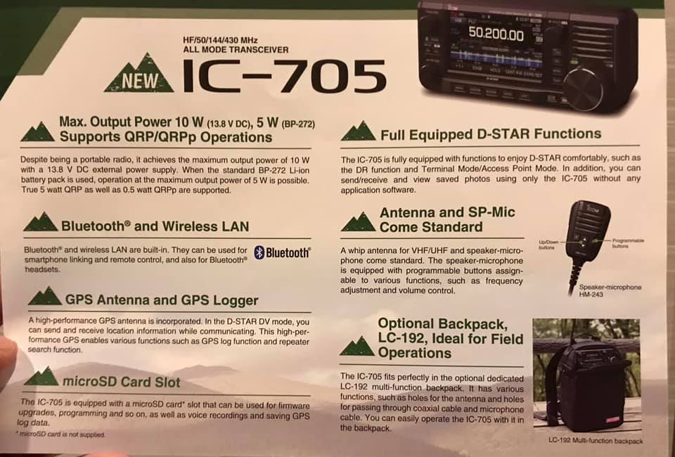
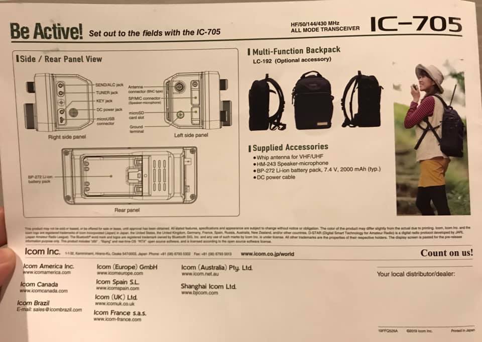
The IC-705 introduces several industry firsts for a backpack portable radio:
It uses the same BP-272 Li-ion Battery pack as the ID-51 and ID-31 series D-Star handy talkies. To my knowledge, this is the only HF transceiver that uses battery packs that can be swapped so easily in the field–like one would swap an HT battery pack
It has a general coverage receiver that spans a whopping 0.5 to 148 MHz
It sports a full color, touch screen with spectrum and waterfall displays
It includes the D-Star digital voice mode
A GPS receiver
Bluetooth connectivity
A MicroSD card slot for memory storage, screen captures and recordings
All of this appears to be included, not add-on options.
The only IC-705 omission, in my opinion, is an internal ATU (antenna tuner). Something I would have expected, but not a deal-breaker for those of us who could really benefit from the amount of features this radio offers.
Side and back panel view noting ports and connections.
There is no word yet on pricing or availability, but you can count on us to post these details once they’re available. If you would like to follow updates, bookmark the tag: IC-705
We will also review on the Icom IC-705 as soon as it’s available.
Video from Amateur Logic/Ham College
Ray Novak (N9JA) with Icom America did a live video interview with Amateur Logic/Ham College TV yesterday. The video includes a full announcement in English from the Icom Booth:
The “Big Three” transceiver manufactures–Icom, Yaesu and Kenwood–have not shown a lot of interest in backpackable QRP radios over the past two decades.
By “backpackable” I mean QRP transceivers specifically designed for portable use in the field–radios that typically have built-in battery options, internal ATUs, and designed to be lightweight shack-in-a-box units.
Yaesu introduced the FT-817 almost twenty years ago and it lives on today (with modest upgrades) as the FT-818. Kenwood has no portable/backpackable HF QRP radio at this point.
I bet the IC-705 is being introduced today because Icom sees a strong market among field-portable operators who enjoy travel and outdoor radio activities like SOTA (Summits On The Air) and POTA (Parks On The Air). In addition, many ham radio operators live in neighborhoods that are either plagued with radio interference (RFI) or don’t allow antennas to be installed outdoors. Portable radios liberate ham radio ops from their shacks and allow them to set up a station far away from noise or home owner’s associations.
Looking forward…
Again, I’ll be in touch with Icom about the IC-705 and will share updates here when they’re available. I’m looking forward to evaluation this rig when it hits the market!
Many thanks to SWLing Post contributor, Mike Ladd (KD2KOG), who shares the following guest post. Note that the following tutorial is also available as a PDF (click here to download).
Basics to decoding Inmarsat L-Band signals using the RSP SDR
by Mike Ladd
Note: CHECK WITH YOUR LOCAL LAWS BEFORE DECODIING ANY SIGNALS FROM THE INMARSAT SYSTEM
(some text taken and edited from the RTL-SDR Blog website)
This document is not a definitive guide to Satcom, L-Band transmission or the Inmarsat system. This is a collection of information that I have found scatter throughout the internet and re-compiled into a document, this document. My aim is to help you get started and hopefully guide you in the right direction. Expect typographical mistakes, inaccuracies, or omissions
Inmarsat is a communications service provider with several geostationary satellites in orbit. Inmarsat provides services such as satellite phone communications, broadband internet, and short text and data messaging services. Geostationary means that the Inmarsat satellites are in a fixed position in the sky and do not move.
The Inmarsat 3-F(x) satellites have transponders transmitting data in L-Band (1.5 GHz) that can be decoded.
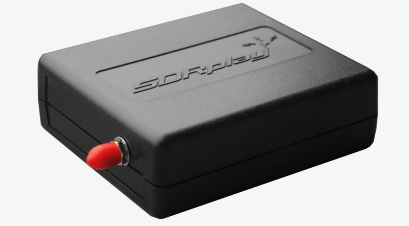
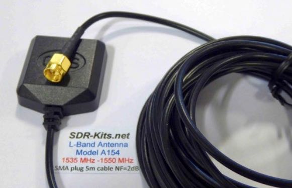
The modes we will cover in this document are Aeronautical (Classic Aero or ACARS) and Inmarsat-C (STD-C) using an RSP1a, RSP2/2pro or RSPduo connected to the SDR-Kits modified L-Band patch antenna. The Inmarsat system is not limited to only these types of networks. We are limited to the decoders available. https://en.wikipedia.org/wiki/Inmarsat
Two of the most popular decoding applications are JAERO used for ACARS and Tekmanoid STD-C Decoder used for decoding STD-C NCS transmissions on the Inmarsat 3-F(x) satellites
Virtual Audio Cable: A virtual audio cable allows you to pipe audio from application (SDRuno) into another application (a decoder like JAERO) digitally. I will assume SDRuno is already installed with your device attached and functioning properly.
You can now download a virtual audio cable package.If you already have a virtual audio cable package installed, you can skip to the next section. If you don’t have a virtual audio cable application installed, you only need to choose one and only install one of the two, either one works fine
Close any running apps, install the virtual audio cable and reboot your computer. When your computer boots back to your desktop, your computer will now have a virtual audio cable pair installed on the system.
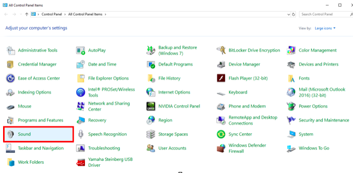
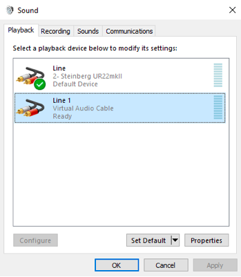
You can verify by going to your Control Panel and double clicking the Sound icon. VB-Cable and Virtual Audio Cable will only install a single virtual audio cable pair, one is for the input (Recording) and one is for the output (Playback). A single pair is all that is needed (as shown below).
JAERO
(some text taken and edited from the JAERO website)
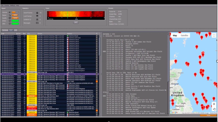
JAERO is a program that decodes ACARS (Aircraft Communications Addressing and Reporting System) messages sent by satellites (in this case Inmarsat) to Airplanes (SatCom ACARS). This is commonly used when airplanes are well beyond VHF range.
JAERO also allows for decoding and demodulation of voice calls, due to local laws and privacy, I will not show or discuss how to do this. You can find more information about that JAERO feature online.
JAERO can be downloaded from the link provided on the first page of this document. After downloading the installer, simply double click the setup file and install it on your primary drive.
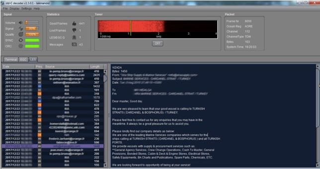
Tekmanoid STD-C Decoder
(some text taken and edited from the USA-Satcoms website)
Inmarsat STD-C is a data or message-based system used mostly by maritime operators. An Inmarsat C terminal transmits and receives on L-Band to various geosynchronous satellites that service each major ocean region.
The Tekmanoid STD-C decoder will decode STD-C Inmarsat EGC (enhanced group call) and LES (land earth station) messages. Some of these messages contain private information. Reception of these messages may not be legal in your country; therefore, your local laws should be checked.
The Enhanced Group Call (EGC) service is a message broadcast service with global coverage (except the poles) within the Inmarsat-C communications system. Two of the services provided are:
FleetNET and SafetyNET
FleetNET is used to send commercial messages to individuals or groups of subscribers (for example, individual companies communicating with their own Mobile Earth Stations (MES). SafetyNET is used for broadcasting Maritime Safety Information (MSI) such as Navigational warnings, meteorological warnings, meteorological forecasts and other safety related information (including Distress Alert Relays) from official sources.
The LES station acts as an interface (or gateway) between the Inmarsat space segment and the national/international telecommunications networks.
The Tekmanoid STD-C decoder requires Java JRE in order to run. The link for the Java runtime environment is on page 2 of this document. For information contact the developer direct [email protected]
There are alternatives to using the Tekmanoid STD-C decoder, but in my opinion the other decoders available do not perform as well on low end systems or even work without needing “helper” applications to be installed. Tekmanoid STD-C decoder is very easy to use and works great on my low-end system using minimal system resources.
Putting all the pieces together
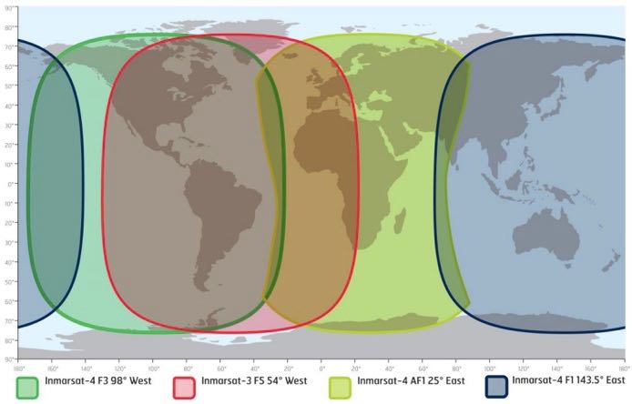
ACARS and STD-C messages will transmit via the Inmarsat satellite deployed within your coverage area/region, you will need to choose the Inmarsat satellite that is closest to your coverage area.
Note that only different frequencies are used between ACARS transmissions and STD-C transmissions. You will only need to receive from one of the available 3-F(x) Inmarsat satellites.
L-Band ACARS transmissions are in the 1.545 GHz range but STD-C messages are on fixed frequencies (shown on page 8)
Since STD-C transmissions are broadcasted on fixed frequencies, we want to monitor the TDM NCSC channel, again these are fixed for the following Ocean Regions. Choose the region closest to your location (page 9).
Inmarsat satellite: Inmarsat-4 F1 (IOR) Direction: 25° East Frequency: 1.537.10 GHz
Inmarsat satellite: Inmarsat-4 F1 (POR) Direction: 143.5° East Frequency: 1.541.45 GHz
I will assume you have located the Inmarsat satellite that covers your region. I suggest using a compass on your mobile phone to pinpoint the general direction. The direction is in ° (degrees). I am referencing true north, not magnetitic north (traditional analog compass). https://en.wikipedia.org/wiki/Magnetic_declination
You can also download an app for your smartphone called Satellite AR (Android and IOS). After you locate the correct direction of the Inmarsat satellite, you will want to place the L-Band patch on a flat metal surface. I have read that the receive pattern of this patch antenna is z (about 85-90°, straight up). Point the top of the antenna facing the Inmarsat satellite. Using the roof of my car worked just fine, just remember to point the front of the antenna at the satellite.
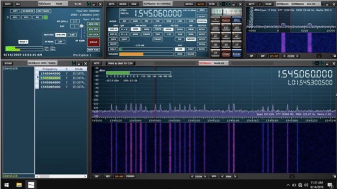
Launch SDRuno and click the PLAY button, remember that if the RSP(x) is in ZERO IF mode, give frequency separation between the VFO (top frequency) and LO (bottom frequency). In LOW IF mode this is not needed. I suggest running a sample rate of 2 MHz, larger bandwidths are not needed.
The SDR-Kits patch antenna requires that the RSP(x) Bias-T be enabled. The Bias-T option is enabled within the MAIN panel of SDRuno. See the SDRuno manual located here. https://www.sdrplay.com/docs/SDRplay_SDRuno_User_Manual.pdf view page 17.
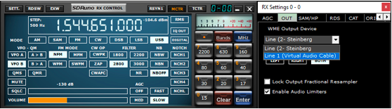
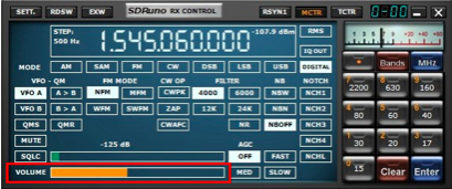
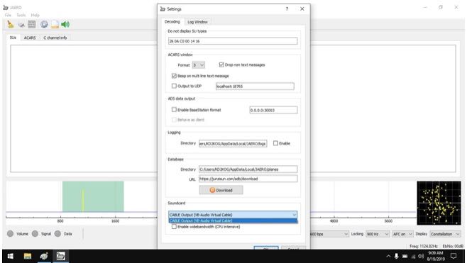
Select the Virtual audio cable as the output in SDRuno, this is selected via the RX Control panel. SETT. button and clicking on the OUT tab.
Have SDRuno’s Volume slider (RX Control) at about 35-40%
Upper sideband is recommended but I found the best mode to use for L-Band ACARS or L-Band STD-C decoding is DIGITAL with a filter width of 3k.
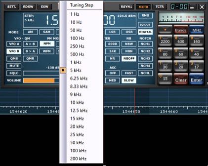
Be sure to set a proper step size (right click the RX Control frequency readout). The step size is not important for STD-C transmissions because these signals are only on one frequency for the satellite in your region but L-Band ACARS signals will be on many frequencies. Setting the proper step size will avoid issues when you point and click on signals you want to decode using the JAERO decoder.
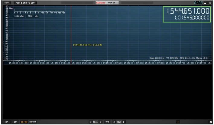
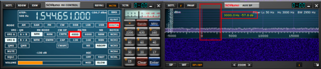
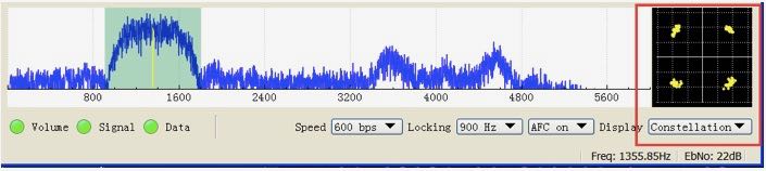
You will want to center the signal with a little breathing room within the AUX SP filter passband. The filter slopes are very sharp. Keep the signal centered and away from the extreme edges (red markers).
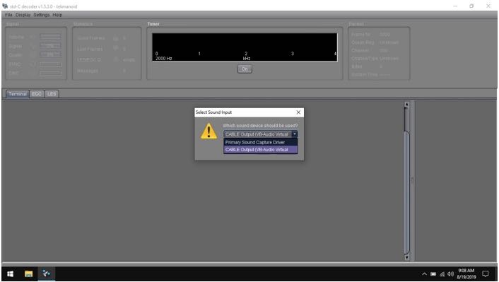
Select your virtual audio cable within the decoder’s audio input preferences.
The Tekmanoid STD-C decoder sound properties are located under Settings in the toolbar menu.
JAERO’s sound settings is located under the Tools menu and Settings.
For STD-C decoding use the frequency from page 8 of this document, remember we only want to monitor the TDM NCSC channel in the Tekmanoid STD-C decoder.
For JAERO decoding, I suggest you start in the 1.545 GHz portion and observe the constellation in the JAERO decoder.
The signal to noise ratio (SNR) needed for successful decoding in these decoders will need to be greater than 7dB. When working with a weak satellite signasls, try decimating the signal using SDRuno’s decimation feature. (MAIN panel, DEC).
I hope this document helps you get started decoding Inmarsat L-Band transmissions from the I3-F(x) satellites. I am sure I missed some key features, remember this is only a primer/basics to decoding these types of transmissions.
Warmest of 73,
Mike-KD2KOG
Many thanks for sharing your tutorial here on the SWLing Post, Mike! This looks like a fascinating activity that really requires little investment if one already owns an RSP or similar SDR. I’m certainly going to give L-Band a go! Thank you again!
Many thanks to SWLing Post contributor, Dennis Dura, who shares the following note from Paul English (WD8DBY), Chief, Army MARS:
DOD Broadcast and Listener Survey on WWV and WWVH
From 14-24 August, WWV and WWVH will be broadcasting a DOD message at 10 mins past the hour on WWV and 50 mins past the hour on WWVH. As part of the message, all listeners are asked to take a listener survey at the URL specified in the message.
The results of this survey are shared with WWV/H personnel to show their NIST chain of command how often their stations are monitored and how the various timing signals and messages are used by the listeners.
Please take a listen to this message and take the survey…as the saying goes, “every vote counts” and your input to this survey is being used to help demonstrate the importance of these stations.
Thanks for your consideration in this effort.
Paul English, WD8DBY
Chief, Army MARS
Many thanks for sharing this, Dennis. Readers have also shared this ARRL News item urging listeners to take the DOD survey.
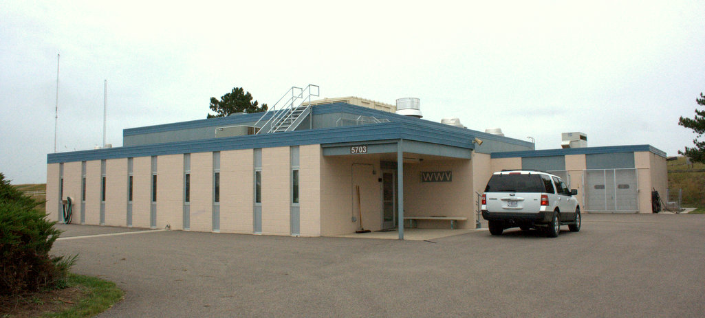
WWV’s transmitter building in Fort Collins, Colorado (2014)
(Source: ARRL via Eric McFadden)
WWV Centennial Committee Prepares for Trial Run of WW0WWV Special Event
The WWV Centennial Committee reports that it will conduct a trial run of special event station WW0WWV over the August 24/25 weekend.
Radios and antennas began arriving last week, and a tower and beam will be erected, along with several vertical antennas. WW0WWV will be set up adjacent to the WWV transmitter site in Fort Collins, Colorado. WWV turns 100 years old on October 1.
“We’ll be testing band and notch filtering, in an attempt to reign in the extreme RF environment created by WWV and WWVB,” said Dave Swartz, W0DAS, of the Northern Colorado Amateur Radio Club (NCARC).
The club will carry out the special event operation in conjunction with the WWV Amateur Radio Club and the National Institute of Standards and Technology (NIST), which operates WWV/WWVH/WWVB.
The special event site is within 1/3 of a mile of all six WWV transmitters and the 50 kW WWVB transmitter. “On-air tests will start Saturday afternoon, August 24, and run through Sunday, August 25,” Swartz said, adding that organizers will post specific times and frequencies on the WWV Centennial Committee website.
The WWV Centennial special event is set to run from September 28 through October 2, and round-the-clock operation will take place on CW, SSB, and digital modes. Operations will shift among HF bands following typical propagation and will include 160 meters as well as satellites (SO-50, AO-91, and AO-92) and 6-meter meteor scatter.
Up to four stations will be on the air for routine operations. A fifth station will schedule contacts with schools, universities, and museums, as well as conducting unscheduled contacts. The additional station will periodically broadcast an AM carrier from a radio locked with WWV’s 10 MHz signal.
“At this point we have filled our operator’s slots and met equipment goals, but we need more financial resources to cover basic operating expenses, return shipping, and site logistics,” Swartz said. Members of the Amateur Radio industry have contributed equipment, including radios, amplifiers, and antennas.
NIST has announced that it will not be able to open the doors of WWV to the public for the event. “Due to a number of reasons, the scope of the formal celebration will be limited to only 100 invited participants,” the WWV Centennial Committee announced. “WW0WWV will be the main public event for the centennial celebration.”
Visit the WWV Centennial Committee website at http://wwv100.com/ to see how you can get involved.
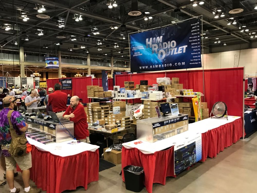
As promised by Huntsville Hamfest veterans, Sunday was a more relaxed day at the Huntsville Hamfest than Saturday (which was insanely busy–in a good way).
Since we had a table in the vendor section of the hamfest, I started taking many of the photos below before the doors officially opened. As you’ll see, all of the major radio manufacturers and retailers were present in Huntsville. It’s no surprise, as it turns out Huntsville is the third largest hamfest in North America (Orlando Hamcation is #2 and Hamvention #1).
Yesterday (Saturday, August 17), was the first day of the Huntsville Hamfest in Alabama.
Over the years, I’ve heard from a number of friends that Huntsville is a must-see hamfest. And, boy, were they right! Turns out the Huntsville Hamfest is one of the largest hamfests in North America.
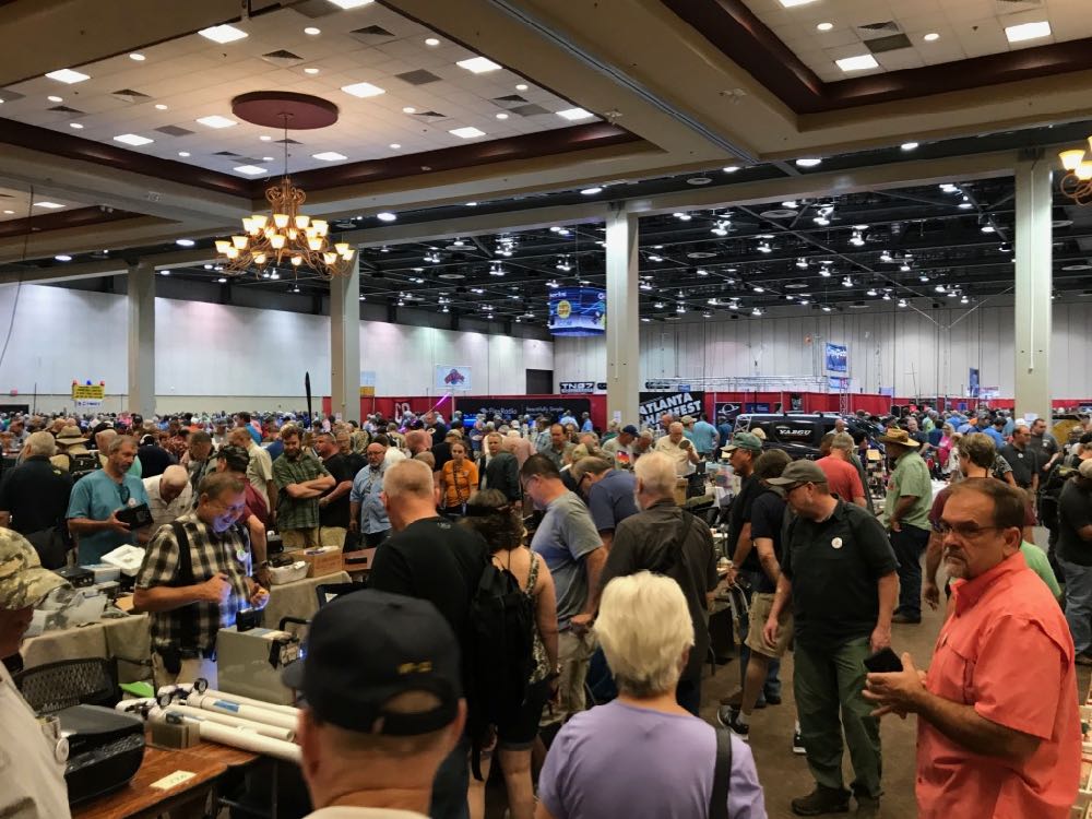
The entire event is held in the amazing Von Braun Center and is fully air conditioned–a good thing as temperatures were pushing 100F/37.8C yesterday!
I took a number of. photos in the flea market area of the hamfest. In truth, though, this is only a small sampling of what was there. I told a friend that–in terms of selection and radio density–this was one of the best hamfest flea markets I’ve ever seen. If you were looking for ways to rid yourself of your hard-earned cash, this was the place to do it!
Click on the photos in the gallery below to enlarge each image. Note that I plan to take photos of the vendor/club areas today and hopefully post them tomorrow: