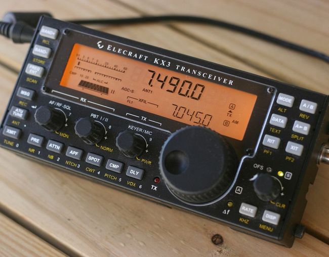
 I’ve owned my Elecraft KX3 for five years, and this little rig continues to amaze me.
In 2013, I gave the KX3 one of the most favorable reviews I’ve ever published–and it continues to hold its own. That’s why last year I recommended the KX3 to my buddy and newly minted ham radio operator, Sébastien (VA2SLW), who had already been eyeing the KX3 as his first HF transceiver.
A few weeks ago, Sébastien bit the bullet and is now the proud owner of a KX3 with built-in ATU. He purchased the KX3 with plans to do a lot of field operations including SOTA (Summits On The Air) and also use the KX3 at home.
Wednesday, I popped by Sébastien’s flat to help sort through some low-profile antenna options. I had suggested that he not invest in a factory made antenna just yet, but instead explore what he’s able to do with a simple wire antenna directly connected to the KX3 with a BNC Male to Stackable Binding Posts adapter. I’ve had excellent luck using this simple arrangement this in the past with the KX3, KX2 and even the KX1.
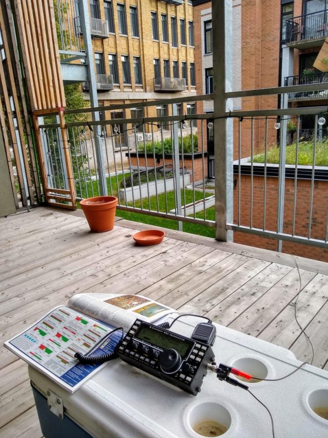
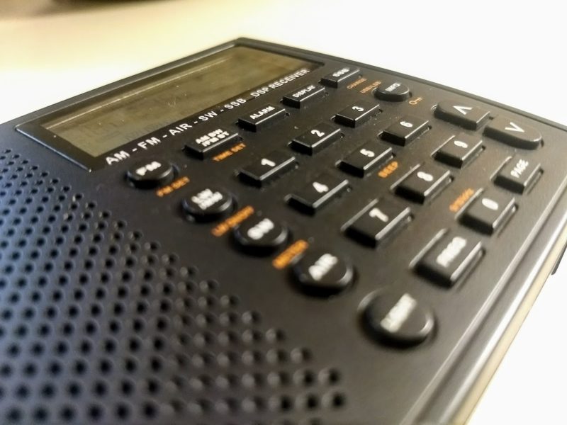
I did a quick QRM/RFI survey of his flat and balcony with my CC Skywave SSB. While there were the typical radio noises indoors, his balcony was pleasantly RFI quiet. At 14:00 local, I was able to receive the Voice of Greece (9,420 kHz), Radio Guinée (9,650 kHz) and WWV (both 10,000 and 15,000 kHz) with little difficulty. His building has incredibly thick concrete walls–I assume this does a fine job of keeping the RFI indoors. Lucky guy!
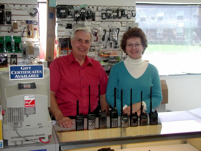
We popped by a wonderfully-stocked electronics shop in Québec City (Électromike–which I highly recommend) picked up some banana plugs and about 100′ of jacketed wire. We took these items back to the flat and cut a 35′ length of wire for the radiator and about 28′ for the ground. We added the banana plugs to the ends of each wire.
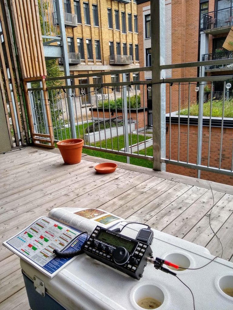
Sébastien temporarily attached one end of the antenna wire to the top of the fire escape and we simply deployed the ground wire off the side of the balcony. Neither of these wires interfere with his neighbors and neither are close to electric lines.
 I had planned to cut both the radiator and ground until we found the “sweet spot”: where the ATU could find matches on 40, 30, 20 and 17 meters (at least).
Much to my amazement, the KX3 ATU got 1:1 matches on all of those bands save 80M where it still could achieve a 2.8:1 ratio. I couldn’t believe it!
Frankly, Elecraft ATUs are nothing short of amazing.
Even the ATU in my little KX2 once tuned a 20 meter hex beam to 40 meters and found a 1:1 match to boot. In contrast, the Icom IC-7300 sitting next to the KX2 wasn’t able to match that hex beam even though we performed a persistent ATU search. Not surprising as I wouldn’t expect a 40 meter match on a 20 meter antenna, but the Elecraft ATU did it with relative ease.
Sébastian did a quick scan of the ham radio bands where we heard a number of EU stations. I also took the opportunity to point out how well the KX3 operates as a broadcast receiver with the AM filter wide open and using headphones in the “delay” audio effects mode. The Voice of Greece sounded like a local station–absolutely gorgeous signal.
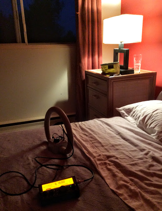
It was getting late in the day, so I couldn’t hang around to call CQ with Séb, but I left knowing that he is going to have a blast playing radio at home and, especially, in the field. Next, he plans to build a simple mag loop antenna, get a BioEnno LiFePo battery and eventually add other Elecraft accessories to his station. I’d say he’s off to a great start!
Want more info? Click here to read my review of the Elecraft KX3 and here to read my review of the Elecraft KX2.
Do you enjoy the SWLing Post?
Please consider supporting us via Patreon or our Coffee Fund!
Your support makes articles like this one possible. Thank you!