Many thanks to SWLing Post contributor, Jock Elliott, who shares the following guest post:
Oh, no, it’s broken – NOT! And other observations on the PL-880
by Jock Elliott, KB2GOM
Okay, okay, I’ll admit it: I’m an oldster, currently enjoying well over 70 trips around that Big Orange Ball in the sky. Further, I’ve been out of SWLing for a while.
Coming back into the hobby after more than a decade’s absence, has been eye-opening. Back when I wrote for Passport To World Band Radio, my main interest, equipment-wise, was tabletop communications receivers hooked to serious outdoor antennas.
Today, however, tabletop communications receivers are hard to come by (there are few new offerings), and, in my situation, serious outdoor antennas present a series of logistical problems that aren’t going to get solved quickly.
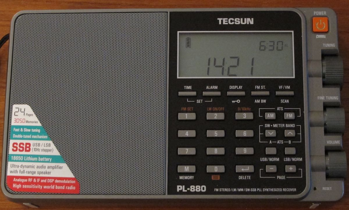
So that has brought me to today’s crop of portable shortwave receivers, and – bottom line – they are pretty darn cool, offering worthy performance on a number of levels. My latest acquisition is the Tecsun PL-880.
Like many of the current SW portables, it offers a system for scanning the SW bands and automatically storing the stations it finds into memory. On the PL-880, it’s called ATS (for Auto Tuning Storage.) Oh, you knew that. Yeah, but did you know that the PL-880 has, essentially, two ATS systems?

The down arrow activates ATS Mode A, and the up arrow activates ATS Mode B.
Check it out: If you press the DOWN arrow button (in the SW-METER BAND rectangle), the ATS Mode A system searches the band you are in (FM, MW/LW or SW, including ALL the SW meter bands), automatically stores stations it finds, and “previously stored radio stations will be replaced automatically by the newly found stations.” Each band has its own set of memories, so that SW stations will be stored in SW memories, FM stations will be stored in FM memories, and so forth.
ATS Mode B, however, behaves differently. You can activate it by pressing the UP arrow (in the SW-METER BAND rectangle). If you are in SW frequencies, ATS Mode B will search and store stations only within the current SW meter band. Further, it will NOT overwrite memories, but will start storing stations it finds, starting with the first available unused memory. Pretty neat.
You can, however, fool yourself. I ran ATS Mode A on SW frequencies one night and found a station that was broadcasting unusual stuff (Kennedy assassination, UFOs, and the like). A couple of nights later, I wanted to see what the night’s topic was on that station, so I punched the button to access memories and found . . . nothing! Oh, no, it’s broken!
Then I realized I was in SSB mode, and, it turns out, the PL-880 has a separate set of memories for SSB. (And the manual says that explicitly.) I switched off the SSB mode, and – tah-dah! – the SW memories reappeared. Sometimes it really does pay handsome dividends to read the manual.
One of the slick things about the PL-880’s memory setup is that, when you are in memory mode for a particular band, you can easily scroll through the memories simply by turning the tuning knob.
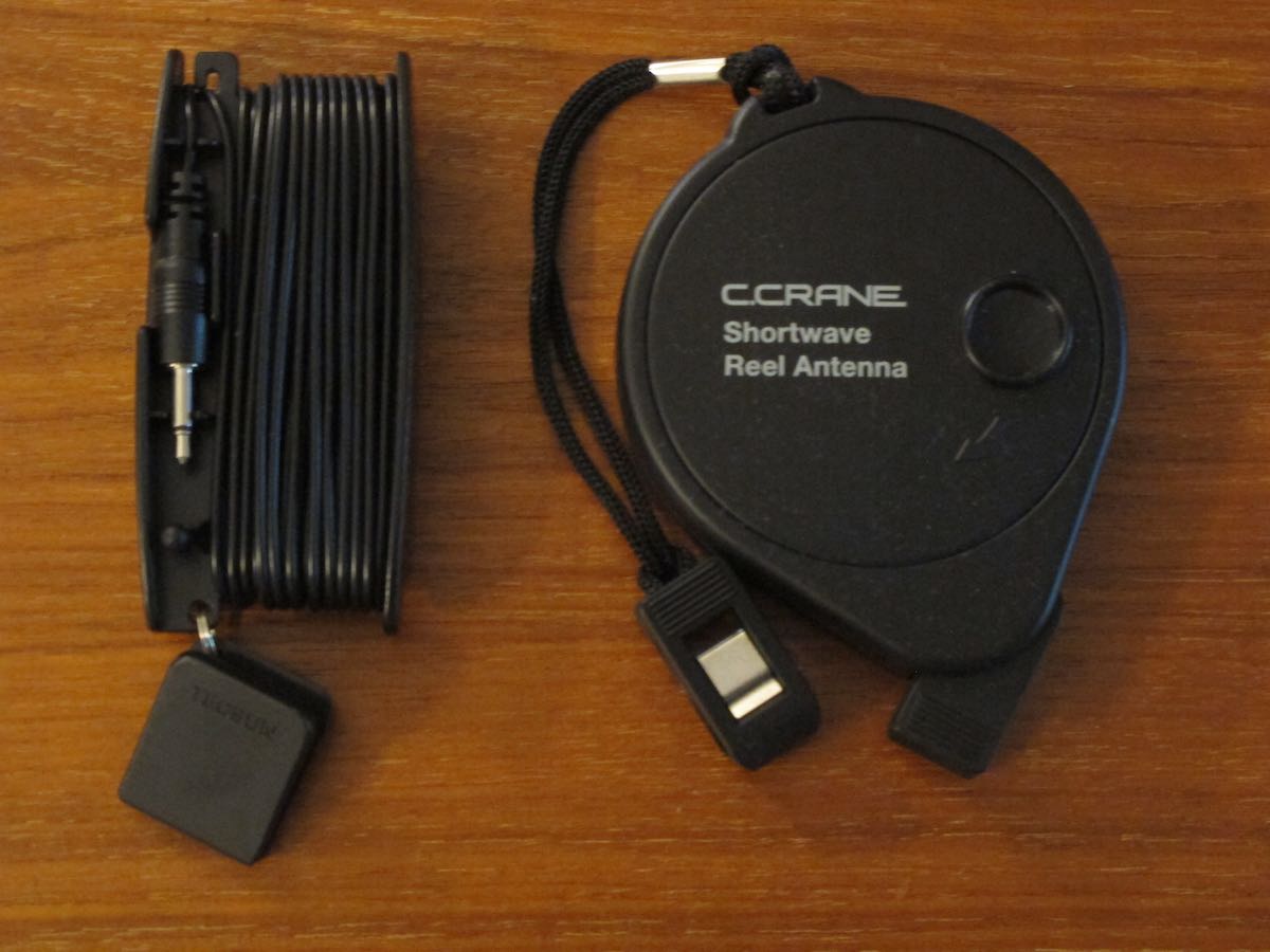
Wire antenna reels come in different styles. PL-880 (left) and CCrane Skywave SSB. But both improve performance for their respective radios.
The PL-880 has a nice long whip antenna (nearly twice as long as the CCrane Skywave SSB’s antenna), and it seems to be quite sensitive operating off the whip. But if you take the time to deploy the external wire antenna that comes with the PL-880, there is a considerable gain in sensitivity. Tuning around the 40-meter ham band, with the external wire antenna plugged into its socket, I could hear two stations in conversation, one louder than the other, but both copyable. When I tried to listen to the same pair of stations with just the PL-880’s whip antenna, the fainter station disappeared entirely, and the louder station was “down in the mud” but copyable. So the external wire antenna is clearly worth using.
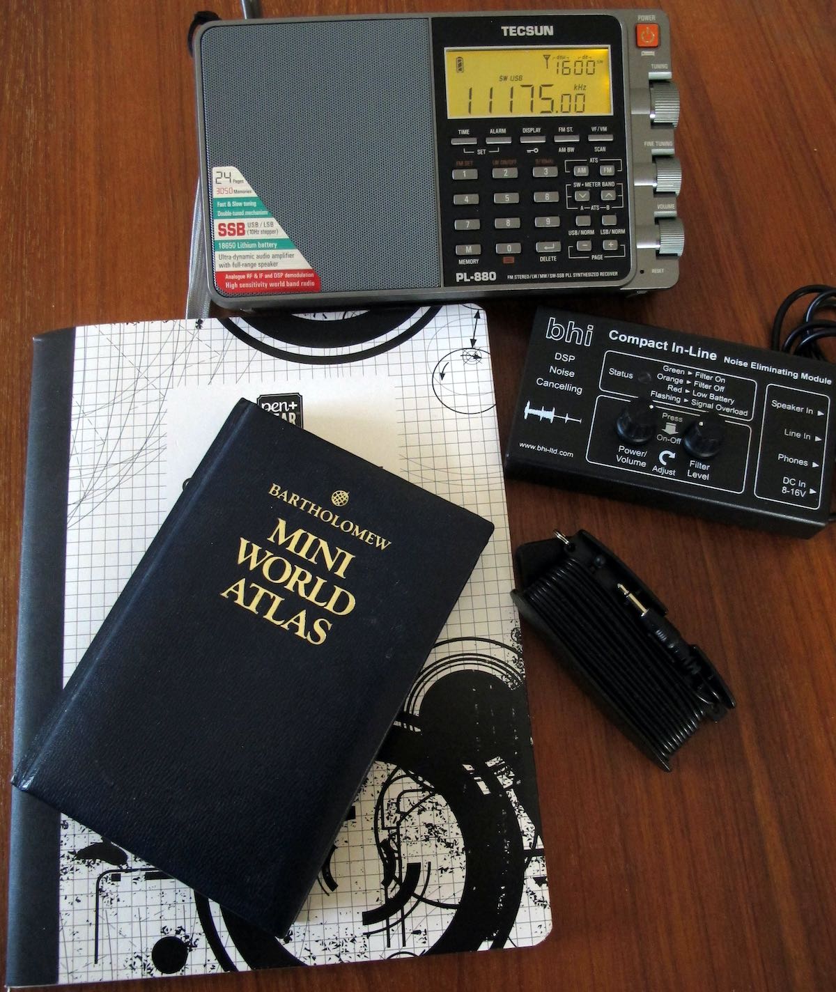
So far, I am well pleased with the PL-880.
PS: Here’s a link to a really good article on extending the wire length of the reel-up antenna that came with the PL-880: https://www.hamuniverse.com/shortwavereelantenna.html

 The Essential Listening Post