Shortwave listening and everything radio including reviews, broadcasting, ham radio, field operation, DXing, maker kits, travel, emergency gear, events, and more
Don Moore’s Photo Album:
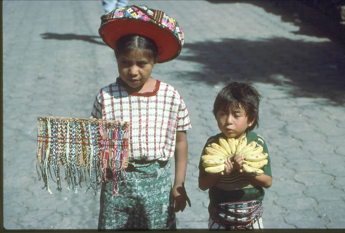
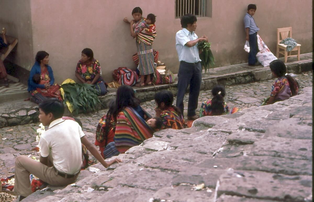
Guatemala (Part Six) – Huehuetenango
by Don Moore
More of Don’s traveling DX stories can be found in his book Tales of a Vagabond DXer[SWLing Post affiliate link]. If you’ve already read his book and enjoyed it, do Don a favor and leave a review on Amazon.
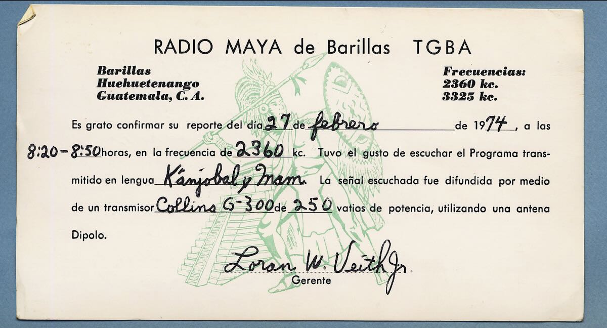
I first heard of Huehuetenango in February 1974. I had gotten my first serious receiver, a Barlow-Wadley XCR-30, a few weeks earlier. Now I could try for stations in the 120-meter band. The first one I heard was Radio Maya de Barillas on 2360 kHz from a place named Barillas in Guatemala. And Santa Cruz de Barillas (the town’s full official name) was in a department named Huehuetenango. The name sounded exotic and magical.
In my mind, Radio Maya de Barillas was the ultimate DX target. The Evangelical Protestant station used a tiny amount of power in 120-meters, the shortwave band that provided the most challenge to DXers. The programs were in Mayan languages with mostly hard-to-pronounce names. And my map showed that Barillas was literally at the end of the road. There was nowhere to go beyond Barillas.
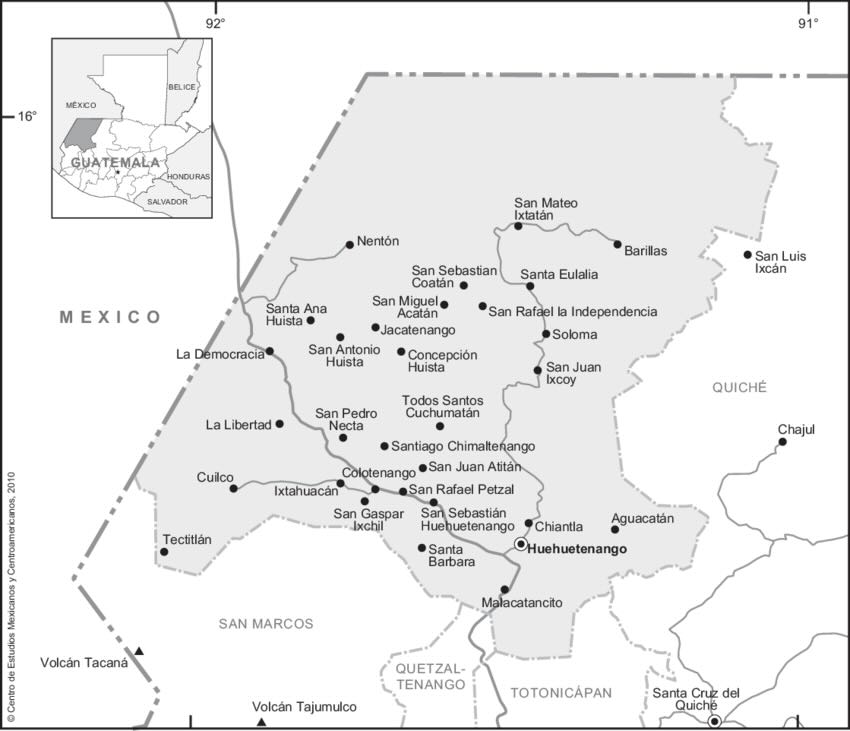
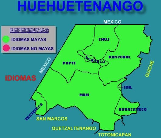
That sense of Huehuetenango being on the edge of civilization was totally correct. The department contains the rugged Cuchumatanes mountains, the highest non-volcanic mountains in Central America. It’s the only place in Central America where it’s too cold to grow corn. Instead, people get by raising sheep and planting potatoes. The mountains explain why eight different Mayan languages (belonging to three different language families) are spoken in this one department. Steep rugged mountains are a barrier to communication. A lack of communication causes a common language to diverge into multiple languages over just a few centuries.
The Mam, numbering about half a million, are the fourth largest Mayan group in Guatemala and their homeland extends into other departments in the south. But the other seven languages are only found in Huehuetenango with maybe a little spillover across the borders. The largest of those is Kanjobal, spoken by about 80,000 people today. The Tectiteco (Tektik) number just a little over two thousand.
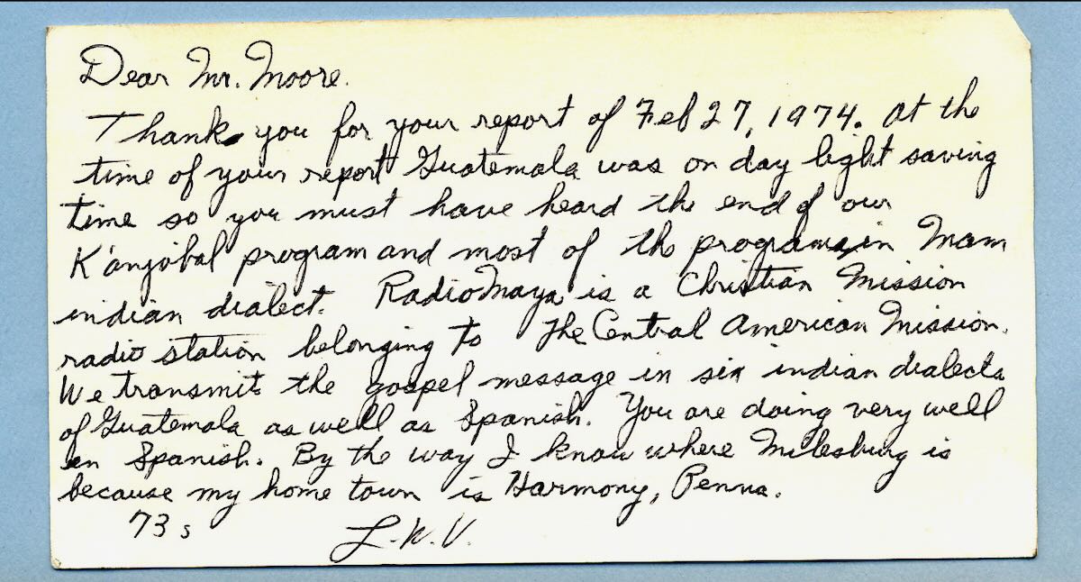
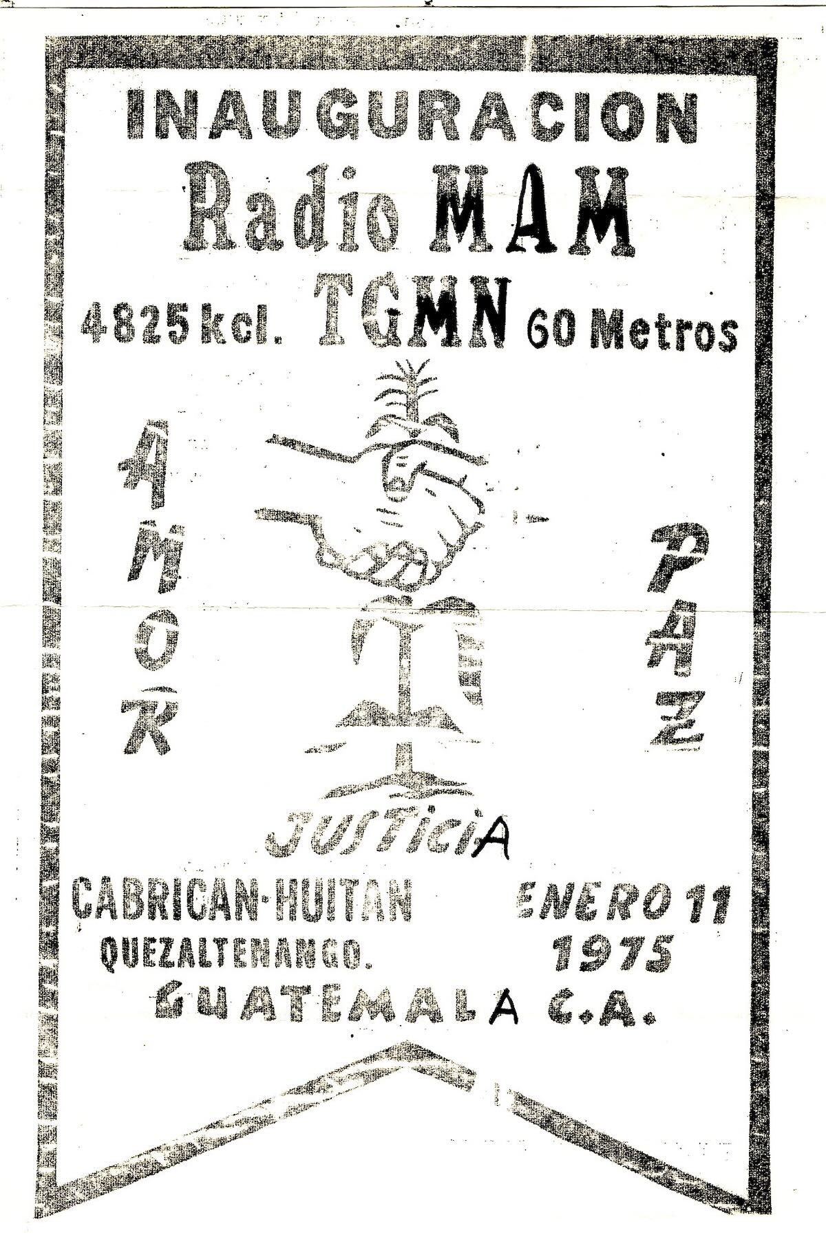
As noted on the back of my QSL from Radio Maya de Barillas, that station broadcast in six of the region’s languages, including Mam and Kanjobal, the language spoken in and around the town of Barillas. For about a decade Radio Maya was the only radio station to broadcast in the region’s languages. Then in 1975 the Roman Catholic church opened an educational station, Radio Mam, in Cabricán to the south in Quetzaltenango department. But Radio Mam only broadcast in the Mam language. (And, unfortunately, I never got to visit the station.)
Visiting Huehuetenango (or not)
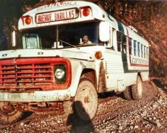
When I was traveling to Guatemala while living in Honduras in the early 1980s, one of my goals was to visit as many Guatemalan shortwave stations as possible. Yet I never once considered going to Barillas. Sure, I knew that the dirt road from the town of Huehuetenango to Barillas was one of the worst in Central America and that the bus ride took twelve hours. That wasn’t going to stop me.
What stopped me from visiting Radio Maya was that Barillas was right in the middle of the area of the heaviest fighting between the government and the guerrillas. This may surprise you if you’ve read the previous parts of this series, but there really were some things back then that I knew better than to do. Going into the worst part of a war zone was one. The closest I came to Barillas was passing through the southern part of the department on the Pan-American Highway on my way to Mexico in December 1984. That was just a few weeks after a guerilla band had ventured south and blown up four bridges on the road. Continue reading →
In the comments section of this recent post about the massive blackout in Europe, SWLing Post contributor Pedro Moreno shared an insightful firsthand account from Madrid. He captured the value of radio during a communications outage so effectively that I wanted to give it more visibility by highlighting it in its own post:
Listener Report from Madrid During the Blackout
By Pedro Moreno
I live in Madrid, and yesterday, after the blackout started, I began to wonder if this was due to a problem with my home electrical installation. Then I expanded my research outside my home to the community premises and discovered that there was a mains shortage as well. So I went further afar and came out to the street to note that there were no noises of electrical tools, and most of the people walking in the street were absorbed looking at their phone screens—only to see there was no data connection.
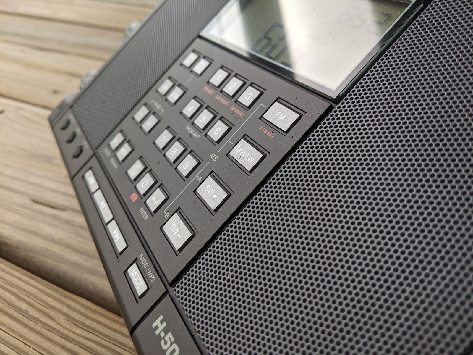
So I came back home and took my Tecsun H501x radio to scan, first on the FM band, just to find out there were some missing stations—for instance, RNE1, RN2, RN3, and Radio Clásica, also a Spanish government broadcaster. Then I knew there was something really bad going on.
Next, I switched to the 7100 kHz band in LSB/USB, where some Spanish radio enthusiasts were commenting on the blackout. There, I found out the blackout was going on in Portugal, Spain, and France. Also, a German radio amateur was commenting on his station about a “blackout in Spain, Portugal, and France as well.” So then, I knew what was going on.
Then I began to search for more information, scanning up and down all the shortwave spectrum looking for more information regarding what was causing the blackout—alas, without finding any specific information about the causes or the expected time for the restoration of the power supply. But I noticed something really new and surprising: the shortwave noise across all the bands was gone, and I could tune into a large number of commercial and amateur stations without noise and quite clearly. That was amazing.
Thank you, Pedro, for sharing this firsthand account. Yes, the only positive in a blackout situation like this is the complete lack of radio interference on portions of the radio spectrum.
I’ll add that in the immediate aftermath of Hurricane Helene, my experience was very similar: the only widely available forms of communication in our region were AM/FM radio and amateur radio.
As SWLing Post contributor qwertymax so perfectly put it:
“In such situations, there are two crucial things needed to get the info delivered, namely: a capability to cover vast distances and the possibility of receiving the signal with a device that uses as low energy as possible – and these are the main traits of analogue radio.”
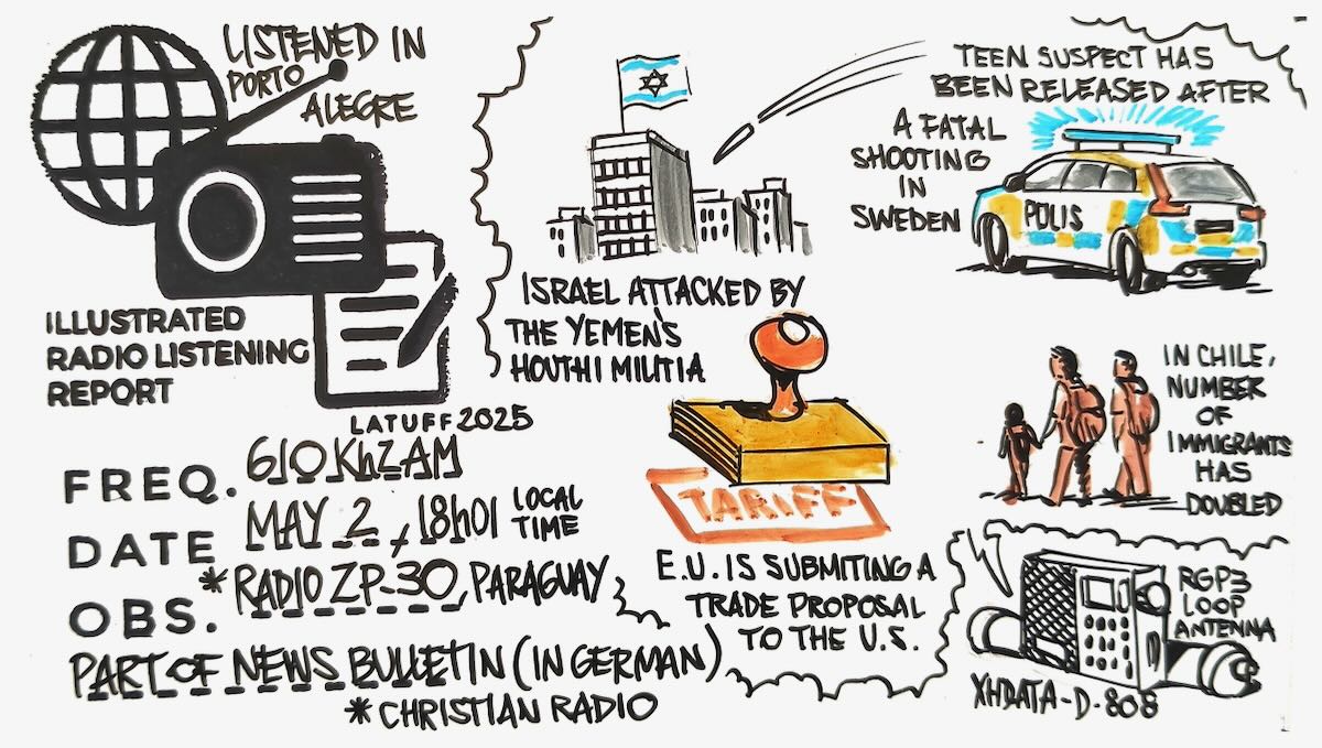
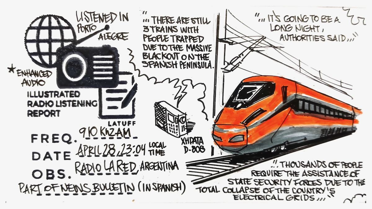
Massive blackout in Spain, Radio La Red, Argentina, 910 kHz AM:
Part of Radio La Red news bulletin (In Spanish) about the massive blackout in Spain. Listened (indoor) in Porto Alegre, Brazil, on a Xhdata d-808 receiver.
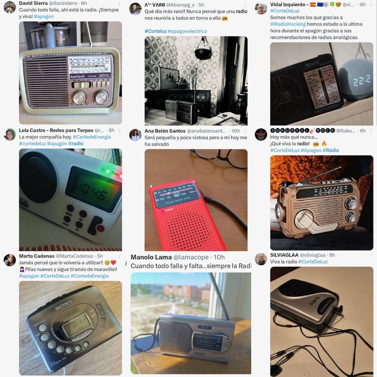
With the massive blackout that hit Spain, Portugal and other regions of Europe on Monday, April 28, once again the good old battery-powered radio proved to be the king. Without electricity, cell phone or Internet signal, people turned to the radio to stay informed. These are just some of the posts that flooded Twitter, from Spaniards grateful to have a simple battery-powered AM-FM receiver in their homes. Does anyone still have any doubts about the importance of the radio?
Many thanks to SWLing Post contributor Dan Greenall for once again sharing a remarkable collection of vintage off-air AM radio recordings. In this post, he shares recordings made from his home and during his travels across North America and the Caribbean.
Dan writes:
Hi Thomas
Judging by the interest on my Internet Archive page, vintage AM radio audio clips from the 1970’s are among the most popular files. In addition to the one posted on the SRAA in September 2023, here are the remaining ones I have to take you back 50 years.
VOA Marathon 1973
The Voice of America station from Marathon Key, Florida is heard signing off on its frequency of 1180 kHz. This recording was made while on vacation in West End, Bahamas in December 1973. Reception of the station in much of North America was tough due to the signal being south beamed to Cuba. However, at least one listener in New Zealand managed reception as evidenced by the attached QSL image from 1972.
ZNS3 Bahamas 1973
ZNS3 radio on 1060 kHz from Freeport, Bahamas is heard with a station identification jingle. The recording was made while on vacation in West End (near Freeport) on Grand Bahama Island in December 1973.
Bermuda AM/FM airchecks 1975
Brief airchecks from 5 local radio stations recorded while visiting Bermuda in March 1975. They are as follows:
ZBM1 1230 kHz
ZBM2 1340 kHz
ZBM-FM 89.1 MHz
ZFB1 960 kHz
ZFB-FM 94.9 MHz
WVMT Burlington VT 1975
Brief aircheck from radio station WVMT in Burlington, Vermont on 620 kHz recorded in March 1975 in Montreal, Quebec. Starts with “Mandy” by Barry Manilow, station ID, then into NBC news.
XERF Ciudad Acuna, Mexico 1971
Short audio recording of radio XERF on 1570 kHz as received in Ancaster, Ontario, Canada in November 1971.
“This is radio station XERF in Ciudad Acuna, Coahuila, Mexico. This is Paul Kallinger, your good neighbor along the way.”
Used a Hallicrafters S-52 communications receiver and a longwire antenna.
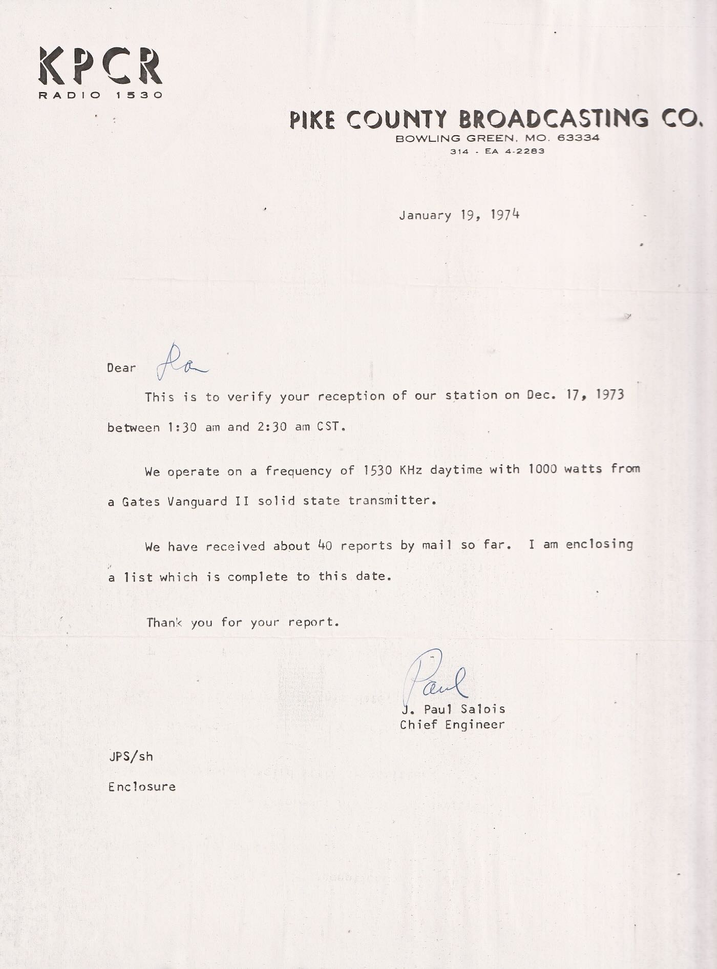
KPCR Bowling Green, MO 1973
KPCR radio in Bowling Green, Missouri as heard in Ancaster, Ontario, Canada on 1530 kHz during an overnight DX test on December 17, 1973. They only ran 1000 watts, but 50 kw WCKY in Cincinnati was off the air that night. Used a Realistic DX150A receiver and a longwire antenna.
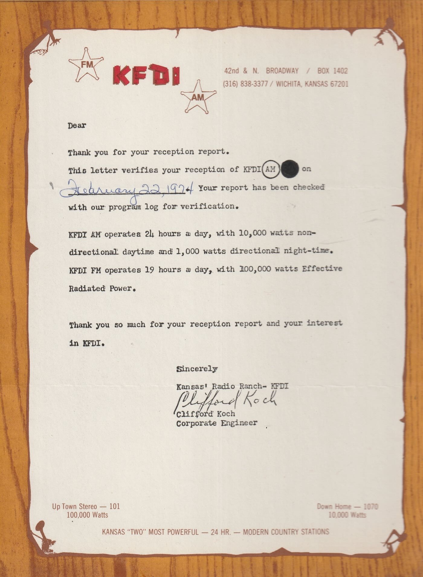
KFDI Wichita, KS 1974
A brief aircheck from KFDI Radio 1070 in Wichita, Kansas as heard in Ancaster, Ontario, Canada on February 22, 1974. Receiving equipment was a Realistic DX150A using a longwire antenna.
WDXR Paducah, KY 1974
WDXR radio in Paducah, Kentucky is heard signing off for their broadcast day. This recording was made circa 1974 while they were operating on 1560 kHz. Receiver location was Ancaster, Ontario, Canada and equipment was a Realistic DX150A and longwire antenna.
WANN Annapolis, MD 1974
A brief aircheck of WANN radio in Annapolis, Maryland heard here signing off for their broadcast day. The recording was made circa 1974 while they were operating on 1190 Khz, A lucky catch for me since WOWO in Fort Wayne, Indiana was usually heard on 1190. Receiver location was Ancaster, Ontario, Canada, (40 miles SW of Toronto) and equipment used was a Realistic DX150A and a longwire antenna.
WCPC Houston, MS circa 1974
One of the easiest ways to log the state of Mississippi on the AM broadcast band in the 1970’s from my location near Hamilton, Ontario, Canada, was WCPC in Houston, MS on 940 kHz around local sunset. Here they are giving a station ID as heard on a Realistic DX-150A receiver and a long wire antenna.
XEMO Tiajuana, Mexico circa 1971
Here is a brief English language aircheck from radio station XEMO in Tiajuana, Mexico as received in Ancaster, Ontario, Canada (a distance of 3392 km or 2108 miles) circa 1971. They were broadcasting on their frequency of 860 kHz. At the very end, there is a quick “X E M O Tiajuana Mexico” in Spanish.
WGR Buffalo, NY 1973
Here is a brief aircheck/jingle from radio station WGR in Buffalo, New York on 550 kHz as recorded in 1973 at Ancaster, Ontario, Canada. That same year, the song “Get Down” by Gilbert O’Sullivan reached number 7 on the Billboard Top 100, and WGR aired it regularly as heard here in the second recording, Most of the time they would just ID as “GR-55”.
Vintage AM radio airchecks 1975 recorded from Bermuda
These brief vintage AM broadcast band airchecks were recorded in March 1975 while vacationing in Warwick, Bermuda at the Belmont Hotel.
1. ZDK, Antigua, West Indies 1100 kHz
2. WKAQ, San Juan, Puerto Rico 580 kHz
3. Radio Paradise, Basse Terre, St. Kitts, West Indies 1265 kHz
4. WHN, New York, NY 1050 kHz
5. WKBR, Manchester, NH 1250 kHz
6. WRKO, Boston, MA 680 kHz
7. CFBC, St. John, NB, Canada 930 kHz
KKJO St. Joseph, MO 1973
In the wee hours of October 28, 1973, this DX recording was made of radio station KKJO in St. Joseph, MO broadcasting on 1550 kHz in the AM broadcast band. My receiving post was some 800 + miles distant in Ancaster, Ontario, Canada. I was using a Realistic DX150A communications receiver hooked up to a long wire antenna. You can hear the station fade gradually in and out a number of times during the recording, but fortunately faded in around the 2:49 mark to catch their station ID and announcement about returning to Central Standard Time. Paul Simon’s “Kodachrome” is heard at first, and Art Garfunkel’s “All I Know” afterward, 2 very popular songs in 1973.
KRLD Dallas, TX 1974
KRLD in Dallas, Texas on 1080 kHz was not heard often at my listening post in Ancaster, Ontario, Canada during the 1970’s. WTIC in Hartford, CT was normally received on this frequency instead. Here is a recording made in early 1974 when KRLD managed to make it through. My receiver was a Realistic DX150A hooked up to a longwire antenna.
Vintage AM radio airchecks 1973 part 2
Here are a few more airchecks from the AM broadcast band recorded in 1973 at Ancaster, Ontario, Canada unless otherwise noted below.
1. WLW Cincinnati, OH 700 kHz
2. WIRK West Palm Beach, FL 1290 (recorded in West End, Bahamas)
3. WINZ Miami, FL 940 (recorded in West End, Bahamas)
4. WSMB New Orleans, LA 1350 (recorded in West End, Bahamas)
5. WDBO Orlando, FL 580 (recorded in West End, Bahamas)
6. WPOM Riviera Beach, FL 1600 (recorded in West End, Bahamas)
7. KFYR, Bismarck, ND 550
8. KWAM Memphis, TN 990
9. WPTR Albany, NY 1540
10. WOKY Milwaukee, WI 920
11. WIBC, Indianapolis, IN 1070
12. WPDX Clarksburg, WVA 750 (special DX test early hours of Feb. 18, 1974)
13. WMAQ Chicago, IL 670
14. WBT Charlotte, NC 1110
15. WNOE New Orleans, LA 1060
16. WSM Nashville, TN 650
17. WJR Detroit, MI 760
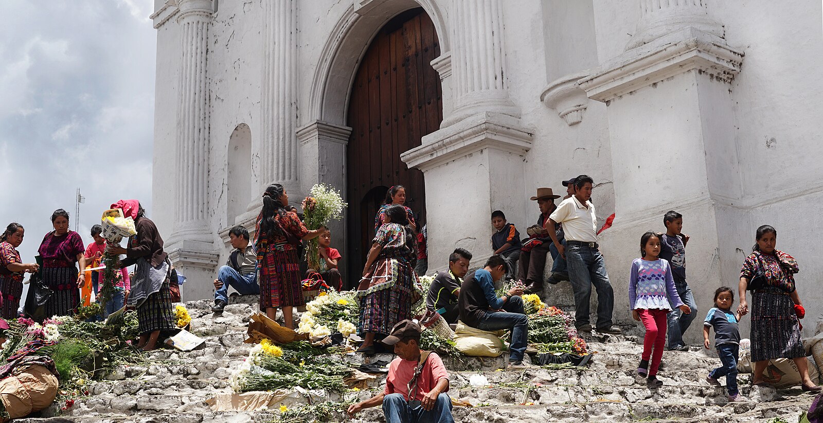
Santo Tomas Church, Chichicastenango, Guatemala (by Lucía García González via Wikimedia Commons)
Don Moore’s Photo Album: Guatemala (Part Five) – Visiting Nahualá
More of Don’s traveling DX stories can be found in his book Tales of a Vagabond DXer[SWLing Post affiliate link]. If you’ve already read his book and enjoyed it, do Don a favor and leave a review on Amazon.
After my first attempt to visit La Voz de Atitlán failed in June 1983, I turned my sights northward. The next morning in Panajachel I boarded a bus bound for Guatemala City but got off when the bus reached the main highway at the Los Encuentros intersection. A few minutes later I caught a ride on a ‘chicken bus’ headed north to my first destination of the day – Chichicastenango.
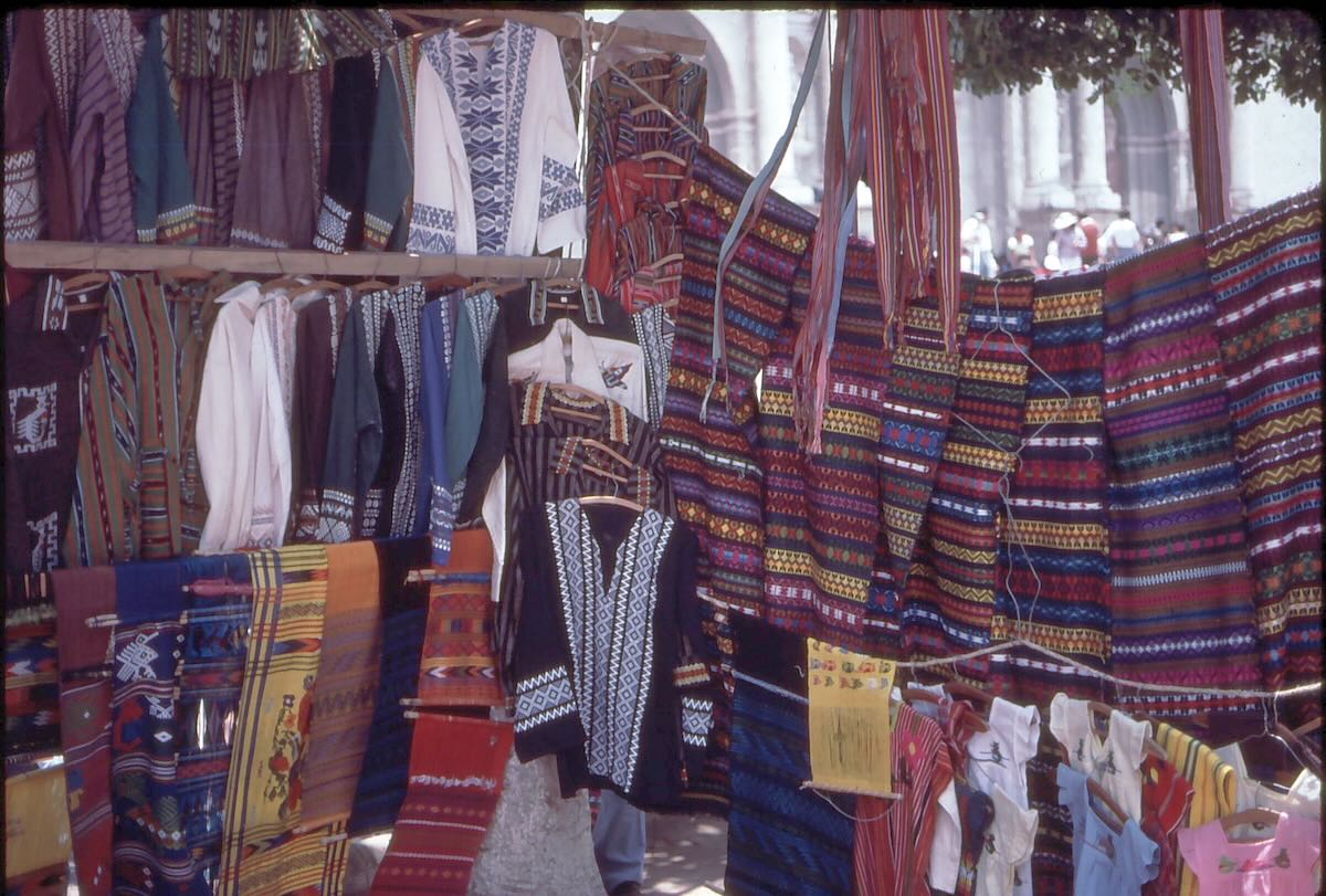
Chichicastenango is not a town that DXers would be familiar with but anyone who has seriously traveled around Guatemala has surely been there at least once. The outdoor markets held on Thursday and Sunday are among the largest in all of Central America. Guatemala has dozens of towns with long names ending in …tenango, meaning “place of.” Chichicastenango is the place of the chichicaste plant, in reference to a thorny bush that grows in the area. Most of the time people just call the town Chichi as it’s common to drop the tenango part from names when speaking.
For over five hundred years, Quiché Mayans from the surrounding area have been coming here twice weekly for the market held in the plaza in front of the Santo Tomás church. The steps to the church are always filled with flower vendors and men swinging containers of incense.
In the early days of the Spanish conquest, Catholic churches were often built on the sites already holy to the Indians. It was a clever way to get the newly forced converts to come to mass. In the case of Santo Tomás, however, they unknowingly picked a location of major spiritual importance in the Mayan religion. As a result many Mayan ceremonies involving nature and natural gods have survived in this area. Some became intertwined with Catholic practices while others were practiced in secret for centuries until it finally became safe to bring them out into the open again.
It was only June but I did my Christmas shopping that day and mailed everything home from Guatemala City a few days later. Guatemala’s post office was very reliable. Everything arrived safely in less than two weeks.
On to Nahualá
With my purchases packed in my now very heavy bag, I got on the next bus heading south and once again got out at Los Encuentros. This time I was looking for any bus heading west. I wasn’t going too far. A few minutes later a bus bound for Quetzaltenango stopped and I got on, telling the driver’s assistant that I wanted to get off at Nahualá.
I knew Nahualá was in the northwest corner of Sololá department a little way off the Pan-American Highway but I was surprised when about an hour later the bus stopped next to a cornfield in the middle of nowhere. I gave the driver’s assistant a puzzled look when he told me this was my stop. He explained that they could leave me off further down the highway where the road to Nahualá branched off. But it would be a long walk from there. From here, the walk was only about ten minutes. There was a well-worn path leading upwards through the cornfield, so I took him at his word. Continue reading →
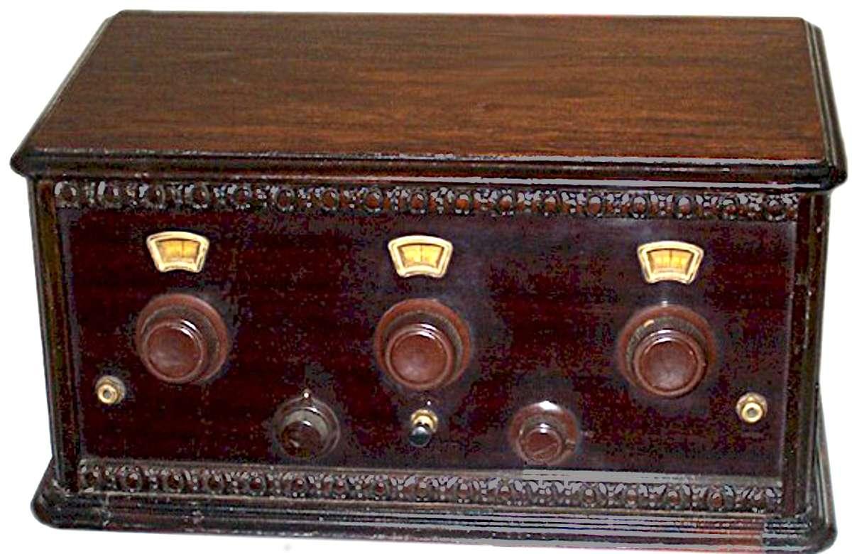
Move along. Nothing informative to read here, just the wandering of an idle mind scheming with meandering fingers on a keyboard. On the other hand, if your curiosity can’t be controlled, consider that a significant amount of enjoyment in this hobby is the mere operation of the radio – seeing what all the buttons, knobs, and switches do, both separately and in combination. It’s always been this way. Beginning in the Amplifiozoic Epoch there was continual rotation of the knobs. This occurred before the discovery of ganged capacitors, when each circuit had to be tuned independently to resonate at the proper frequency. Otherwise, nothing.
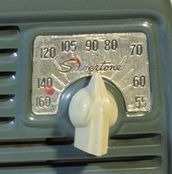
It could be quite confounding for a non-radiofile trying to break into the sport. Just getting some sound out of a two-knob radio could be a challenge. My late mother solved this problem on all our radios by painting a dab of red nail polish at the points on the dial where each local station came in.
The Complexities of Shortwave
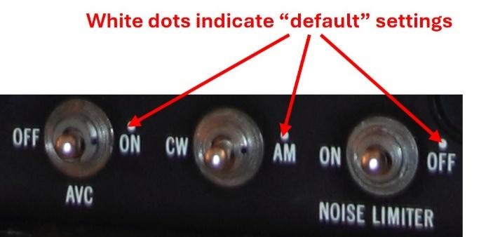
Later, with the humble entry-level shortwave “set” there was conundrum in the way the bandspread interacted with the main tuning control, and the curious effect of the BFO switch. Even the venerable Hallicrafters Company, which catered to the hams and SWLs of the time, recognized the problem. They tried to solve this by prescribing a default setting in installation and operating procedures for model S-40 receiver, The Hallicrafters Company, Chicago, USA, p. 4, 1946:
“NOTE. – Some of the control markings are in RED. This is an added feature incorporated for the convenience of the listener who is not familiar with radio terminology as an aid in setting the controls most used for the reception of standard broadcast stations.”
That was the nice way of saying it. After many years, I still chuckle to myself thinking of an old ham radio mentor of mine who insensitively explained that the purpose of these markings was for certain members of the household who could not otherwise make the radio work. On my S-40B, the “convenience” markings are white dots.
Modern Radios
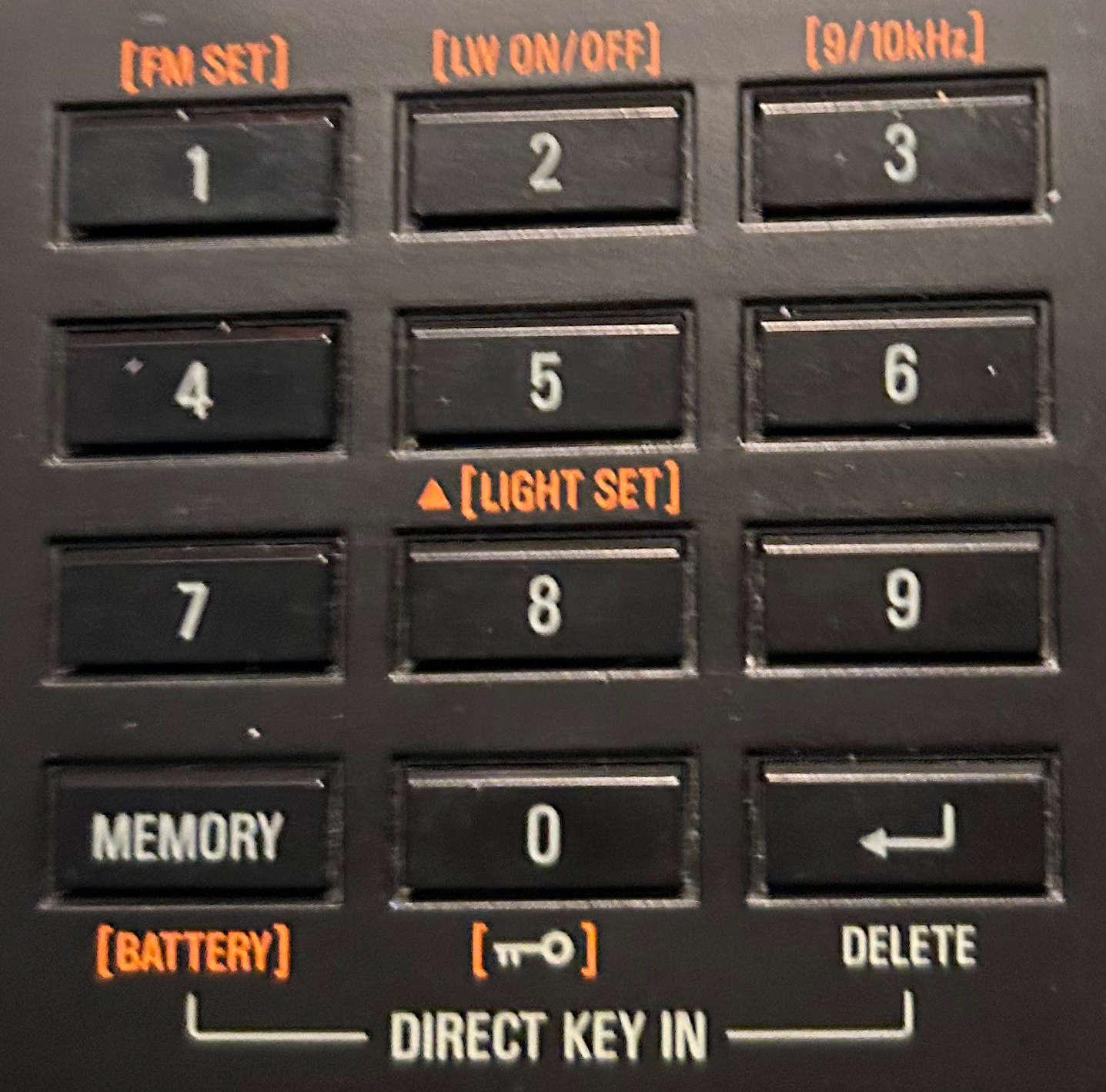
Modern radios have many buttons, which can work in different ways. A short press will do one thing while a long press will do something else. Some buttons do one thing with the radio turned off and another thing with the radio turned on. On many radios you can lock the buttons and knobs, in which case they won’t do anything. You must get it right.
Hidden Features
Today, the possibilities with all these variables are boundless, even beyond the control of the manufacturers who incorporate the complex TEF6686 30-pin IC chips in their designs. Qodosen has set the bar high by making a plethora of user-adjustable functions available on the DX-286. An uncommonly informative 40-page manual has been included with each radio and is highly recommended as an essential tool to assist with its operation.
In recent years, Tecsun has capitalized on this by incorporating “hidden features” in some of their models; that is, their operation and even their very existence are not revealed in the manual. In computer gaming parlance, these features are called “Easter eggs” for which one must hunt. Originally, the inclusion of hidden features may not have been intentional, but with the introduction of the PL-880 in 2013 they became a veritable sensation, as testified by the countless owner postings on the PL-880 Yahoo users’ group of that time. A prize of unbounded esteem and self-satisfaction went to the intrepid listener who discovered and solved a hidden feature. This interest went on for several months as Tecsun tweaked the firmware and the “features” migrated somewhat. But unfortunately, a spoiler has been introduced. Hidden feature data sheets are now packaged with current models. In case you are missing any, here is a sampling.
The complexity of radio operation is compounded still further by the advent of SDR, wherein combinations of various hardware and software components result in a host of possibilities. Features and their placement seem endless as they are distributed on multiple menus. As my personal experience is limited to WebSDR, I leave the pursuit of this point to others.
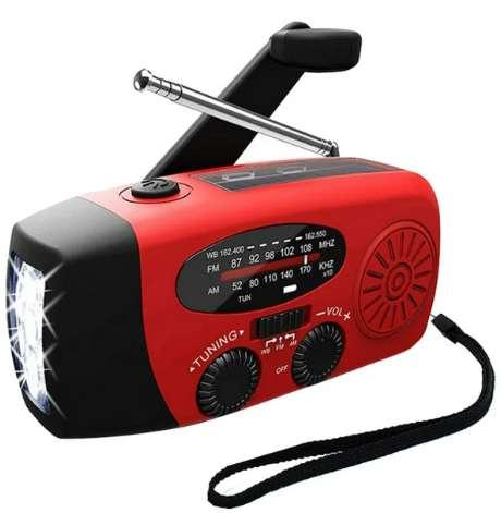
Manual Power Generation
Finally, the inclusion of some elementary form of leverage and dexterity is present in some radios. Isn’t the hand-powered crank on today’s emergency radio akin to the vintage treadle-operated transcription machine pictured at the beginning of this posting? Perhaps we have come full circle.
Conclusion
Today’s radios are a sort of Rubik’s cube which can continually be manipulated to provide many hours of discovery and complement the listening and DXing experiences. So, the next time you crawl underneath the headset and unconsciously tune to the object frequency, zero beat on the necessary sideband, and adjust the proper bandwidth and volume, reflect on all the time and practice it took you to develop this useful skill.
Please support this website by adding us to your whitelist in your ad blocker. Ads are what helps us bring you premium content! Thank you!