 Radio Waves: Stories Making Waves in the World of Radio
Because I keep my ear to the waves, as well as receive many tips from others who do the same, I find myself privy to radio-related stories that might interest SWLing Post readers. To that end: Welcome to the SWLing Post’s Radio Waves, a collection of links to interesting stories making waves in the world of radio. Enjoy!
Many thanks to SWLing Post contributors Michael Bird, Dave Zantow, David Korchin, and Alokesh Gupta for the following tips:
ABC must freeze wages, government warns (The Guardian)
The Morrison government has put the national broadcaster on notice that it expects the ABC to embark on a six-month wage freeze to bring it in line with other taxpayer-funded agencies during the Covid-19 crisis.
The warning follows the government’s decision in early April to defer general wage increases for commonwealth public servants for six months. The public service commissioner followed up that directive by writing to all non-public service agencies – including the ABC – informing them the government expected them to adopt the same practice.
With no clear response from the ABC to the 9 April missive, Guardian Australia understands the communications minister Paul Fletcher wrote to the national broadcaster this week flagging his expectation that the organisation would defer a 2% increase for all employees scheduled to take effect in October under the ABC’s enterprise agreement.[…]
Radio used by the Titanic to call for help can be salvaged, judge rules (CNN)
A federal judge has ruled that RMS Titanic Inc. can salvage the radio used to call for help by the fated ocean liner after it struck an iceberg in 1912.
To get to the radio, divers would need to remove a part of the ship’s deckhand to reach the room known as the Marconi Suite, which houses the device.
The ruling modified an order issued on July 28, 2000, that said that RMS Titanic Inc. could not cut into the wreckage or detach any part of it.
Virginia’s eastern district court amended that order “for a unique opportunity to recover an artifact that will contribute to the legacy left by the indelible loss of the Titanic, those who survived and those who gave their lives in the sinking,” Judge Rebecca Beach Smith wrote.
Experts in the case testified to the “significant deterioration” in areas above and around the Marconi room, according to the document, and photos showed the “increasing breakdown” in the deck above the suite.
The suite, made of steel, consisted of three areas: sleeping accommodations, an operator’s room and the silent room that housed the radio. Each area was separated by wood walls that officials believe have dissolved, according to court documents.
The Marconi device and the artifacts associated with it face “significant threat of permanent loss,” the judge said in her approval of the expedition.[…]
FCC Tweaks LPFM Technical Rules (Radio World)
The FCC in April modified the technical rules covering low-power FM stations. It expanded the permissible use of directional antennas; permitted waivers of protections of television Channel 6 by a specific group of reserved channel stations; expanded the definition of minor change applications for LPFM stations; and allowed LPFM stations to own boosters. Read more about the changes here.
Michelle Bradley, founder of REC Networks, is an engineer and longtime LPFM advocate.
Radio World: What’s your overall assessment of the outcome and the scope of its impact in the LPFM community?
Michelle Bradley: While the FCC did not address three major issues that are impacting LPFM stations right now —the ability to address building penetration issues, the ability to reach “local” listeners in rural areas and the disparity in how LPFM stations protect FM translators vs. how translators protect LPFMs — the changes will benefit current LPFM stations by giving them more flexibility in moving locations, reduce the need for waivers and improve LPFM service in the southern border region. It will also open some additional opportunities for new LPFM stations in the next filing window.[…]
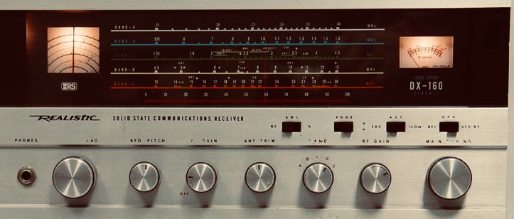
RadioShack Shortwave Goes Digital (Hackaday)
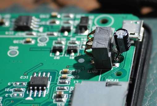
If you spent the 1970s obsessively browsing through the Radio Shack catalog, you probably remember the DX-160 shortwave receiver. You might have even had one. The radio looked suspiciously like the less expensive Eico of the same era, but it had that amazing-looking bandspread dial, instead of the Eico’s uncalibrated single turn knob number 1 to 10. Finding an exact frequency was an artful process of using both knobs, but [Frank] decided to refit his with a digital frequency display.
Even if you don’t have a DX-160, the techniques [Frank] uses are pretty applicable to old receivers like this. In this case, the radio is a single conversion superhet with a variable frequency oscillator (VFO), so you need only read that frequency and then add or subtract the IF before display. If you can find a place to tap the VFO without perturbing it too much, you should be able to pull the same stunt.
In this receiver’s heyday, this would have been a formidable project. Today, a cheap digital display will do fine.[…]
Do you enjoy the SWLing Post?
Please consider supporting us via Patreon or our Coffee Fund!
Your support makes articles like this one possible. Thank you!