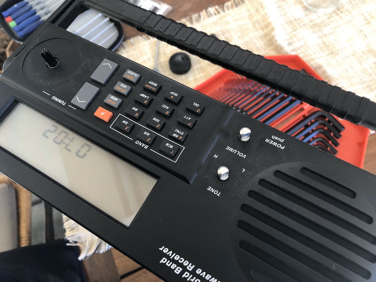
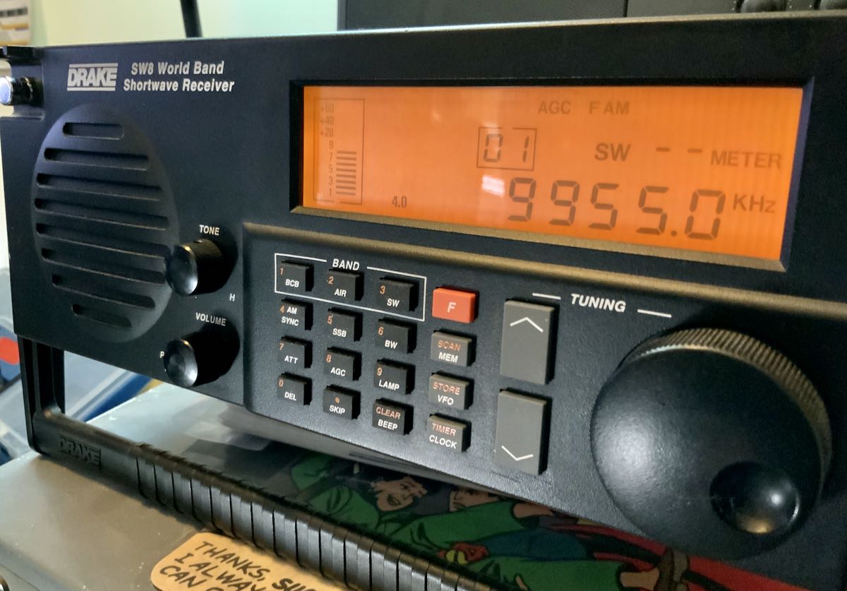
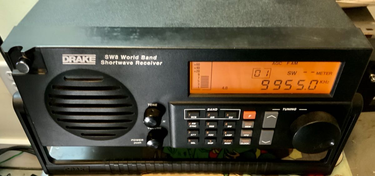
 In 2019, I made an impulse purchase: a Drake SW8 tabletop receiver. As I mentioned previously, I’d always wanted an SW8. My buddy, David Goren, recommended this receiver ages ago, Each time I’ve stayed at his home in Flat Bush, he magically made an SW8 available as my bedside radio in the guest room. (That’s hospitality!)
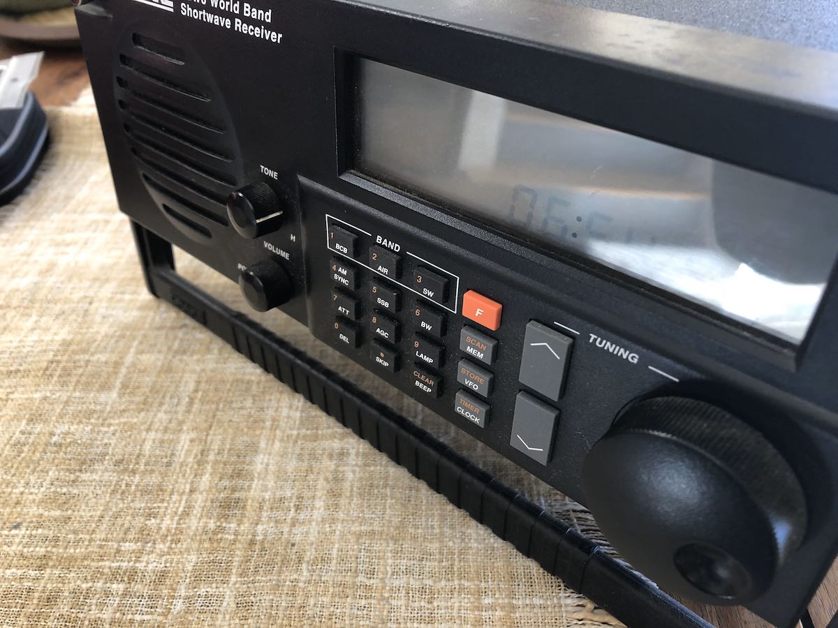
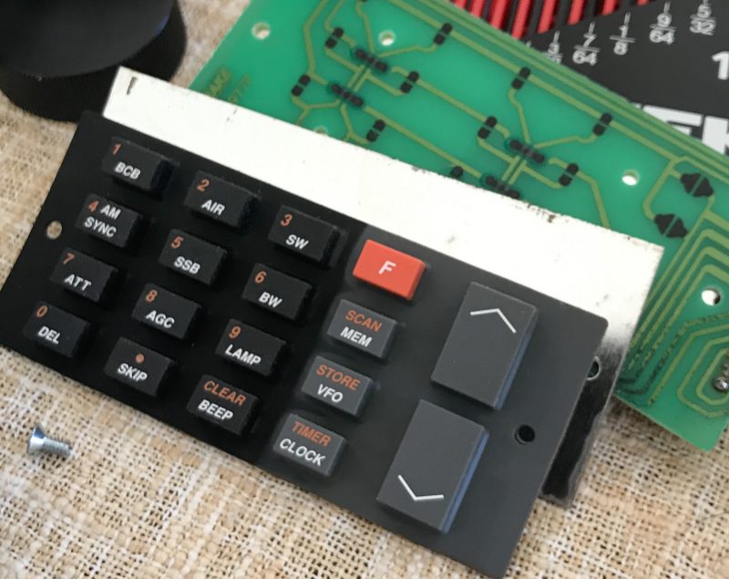
After receiving my SW8 and putting it on the air, I realized it suffered from a common problem found in Drake receivers: a flaky keypad. Several of the buttons didn’t work reliably, or they made multiple contacts on each push, or they didn’t work at all.
What happens is, over time, the black carbon dot on the back of each pad on the rubber membrane simply wears out and no longer makes reliable contact. I believe a number of Drake receivers of the era used the same keypad style (though configured differently).
The seller didn’t realize this when he sold it to me and, frankly, I felt I got a pretty good deal regardless, so never bothered him about it.
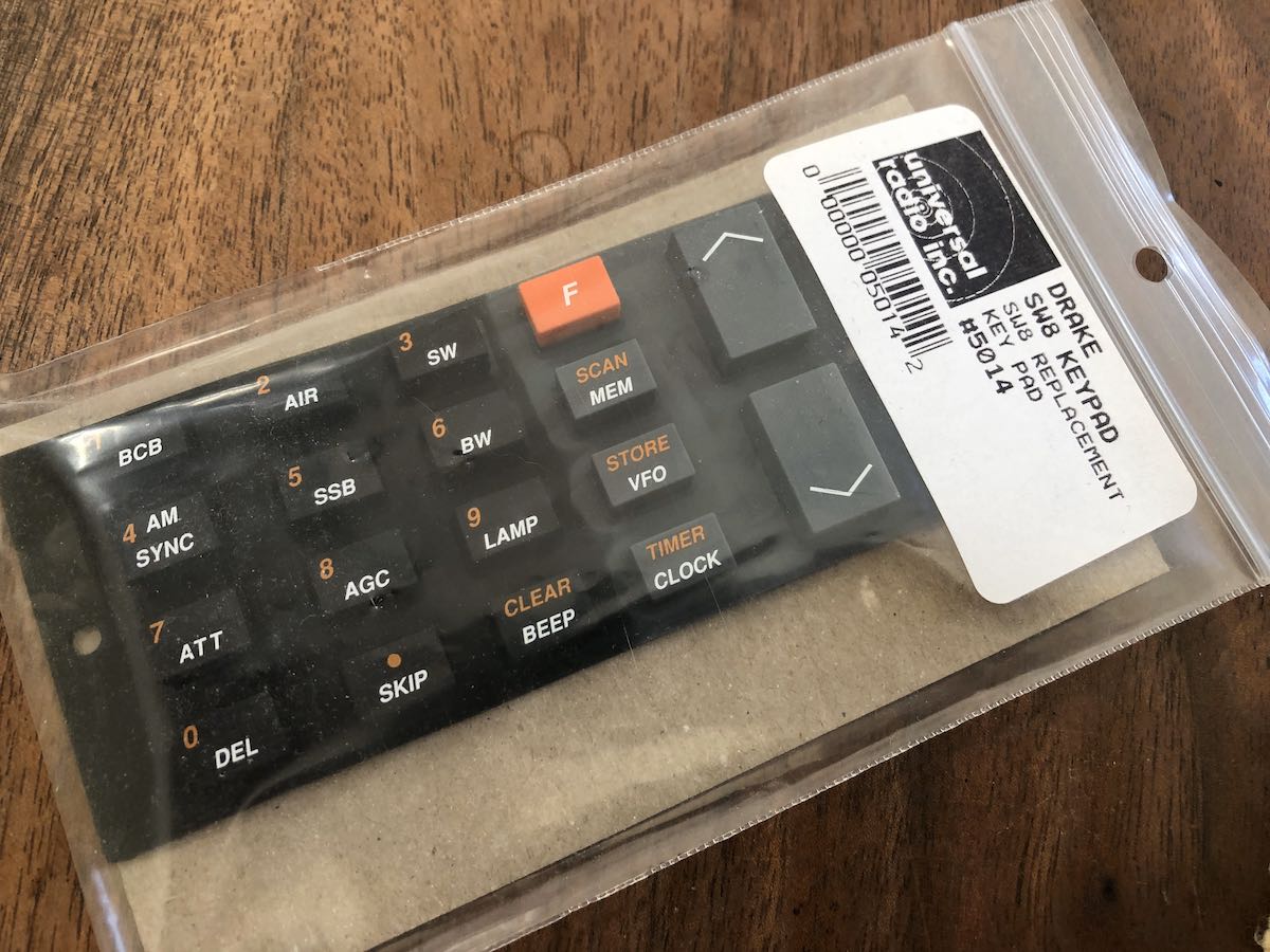
A couple months later, I found out that Universal Radio uncovered a box of new old stock SW8 replacement keyboards, so I ordered one.
2020 got a little out of hand and I put off making the repair. I didn’t want to trouble my buddy, Vlado, who could have done this in his sleep. I knew I could handle a parts replacement as long as I didn’t need to de-solder the keypad from a circuit board (as one does with the SW2, I understand).
Tuesday, I cleaned off one of my radio shelves and found the replacement keypad. I looked at the SW8 and knew it was time to get’er done!
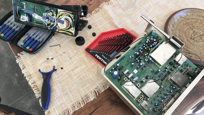
 I first removed the encoder, volume, and tone knobs.
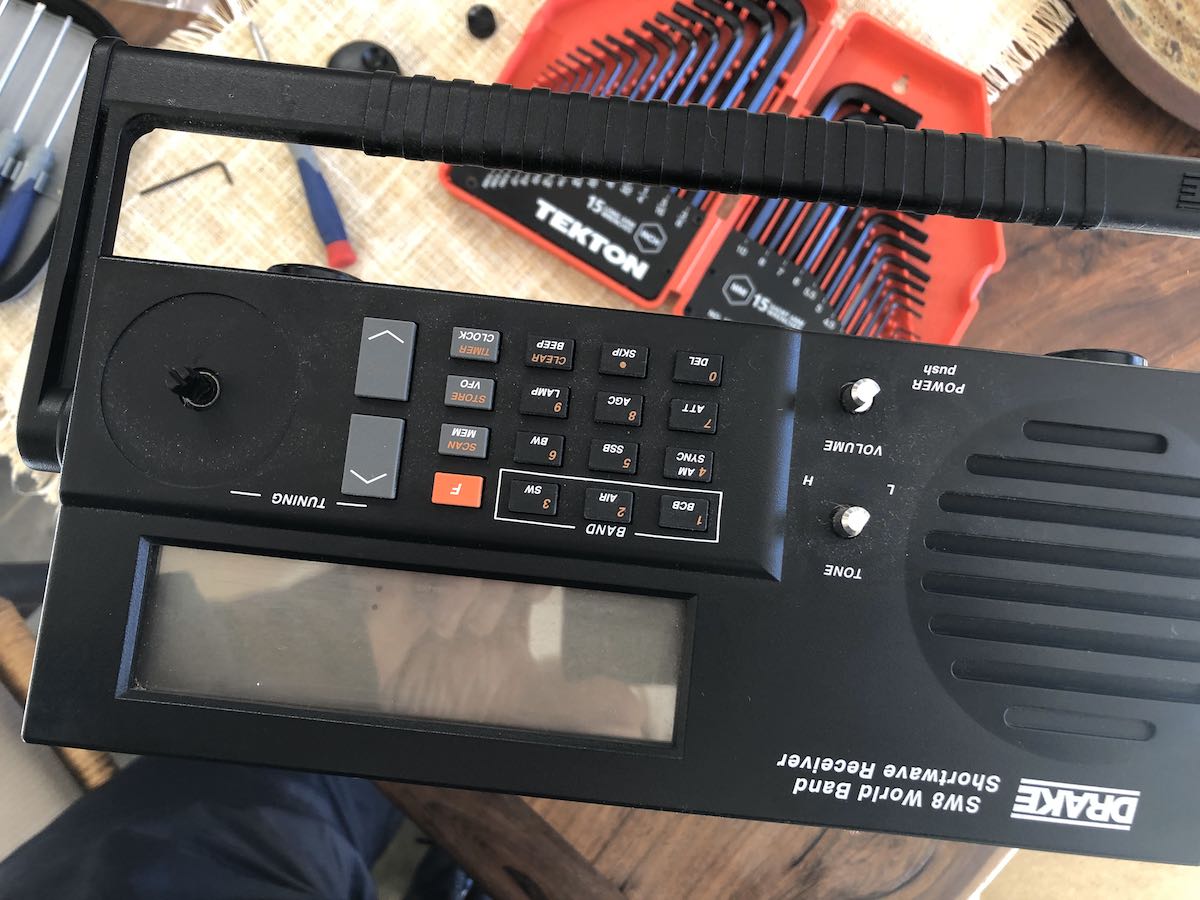
Next, I removed the top cover which is attached with five screws.
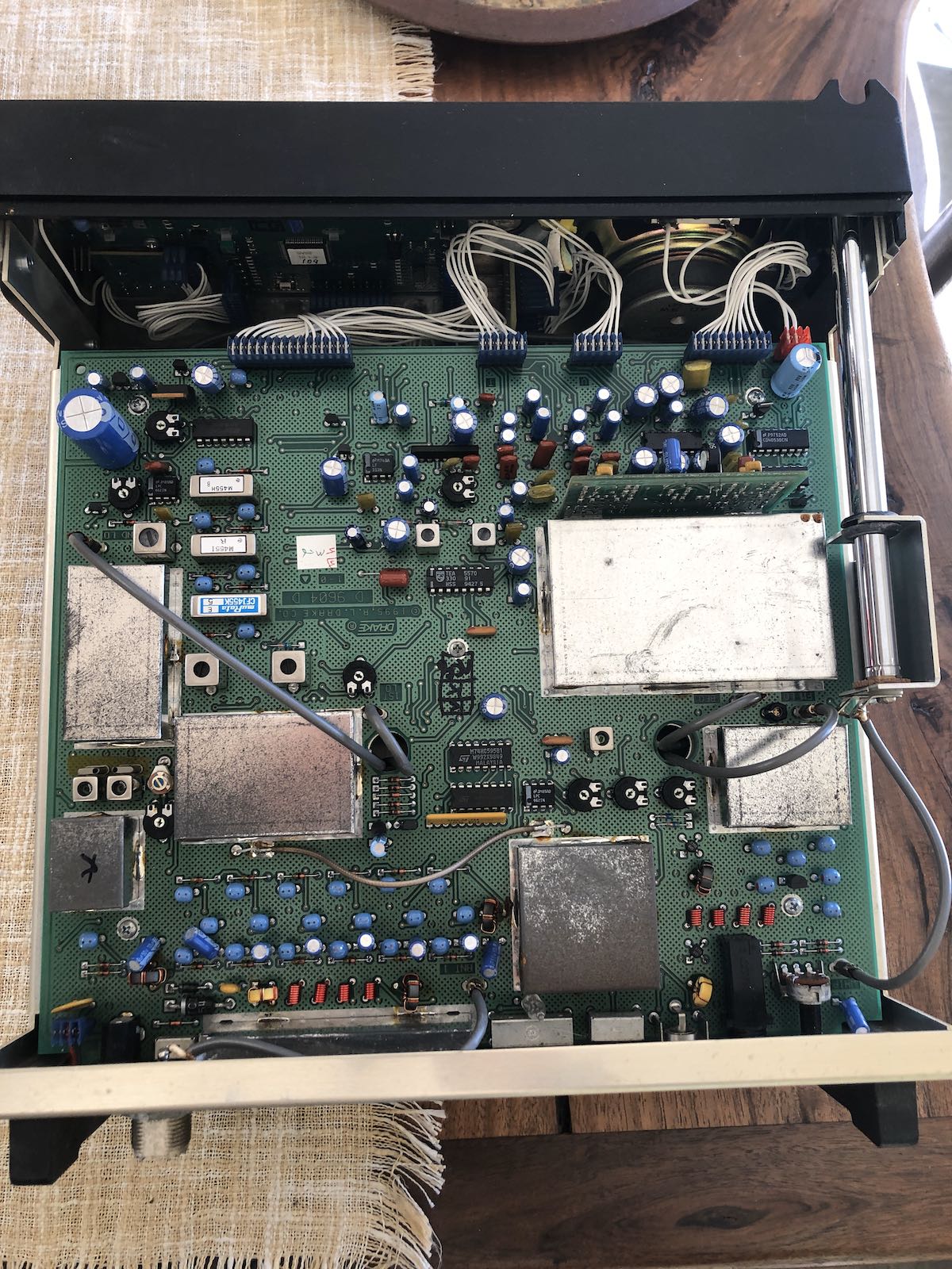
There are a number of multi-pin plugs that attach the front faceplate section to the main body of the radio.
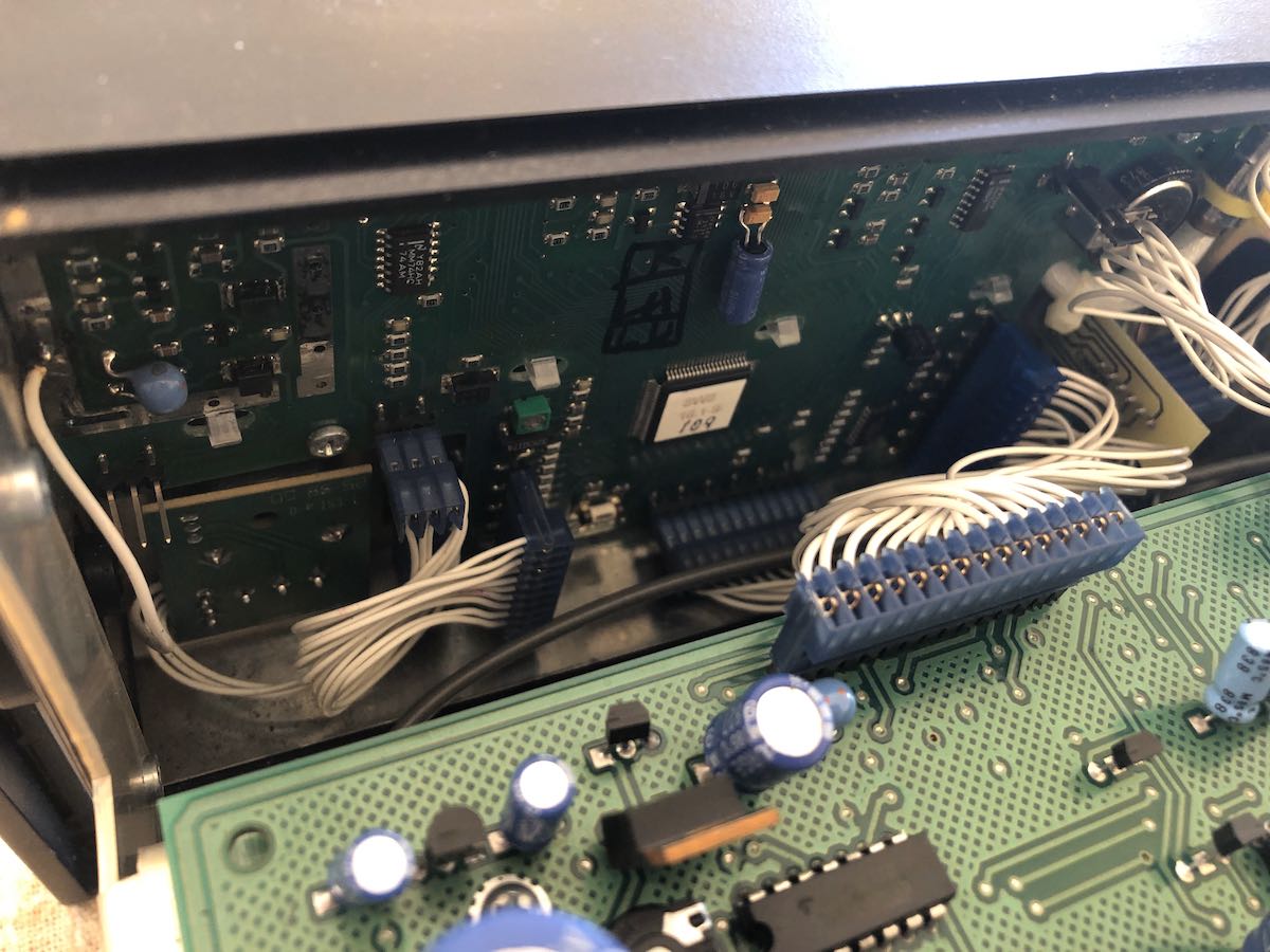
I carefully removed all of them and noted their positions (taking photos at each stage really helps).
I quickly discovered that the keypad was under at least two more board layers.
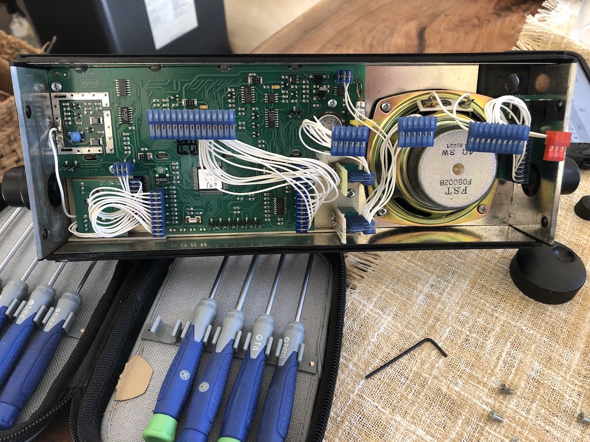
I removed the main board which is held in place with three screws, then the board underneath which is also held in place with three screws.
To my surprise, the keypad, circuit board and two metal plates (in that order) are held in place with compression from the last board layer.
 The keypad, circuit board and metal plates fell out quite easily.
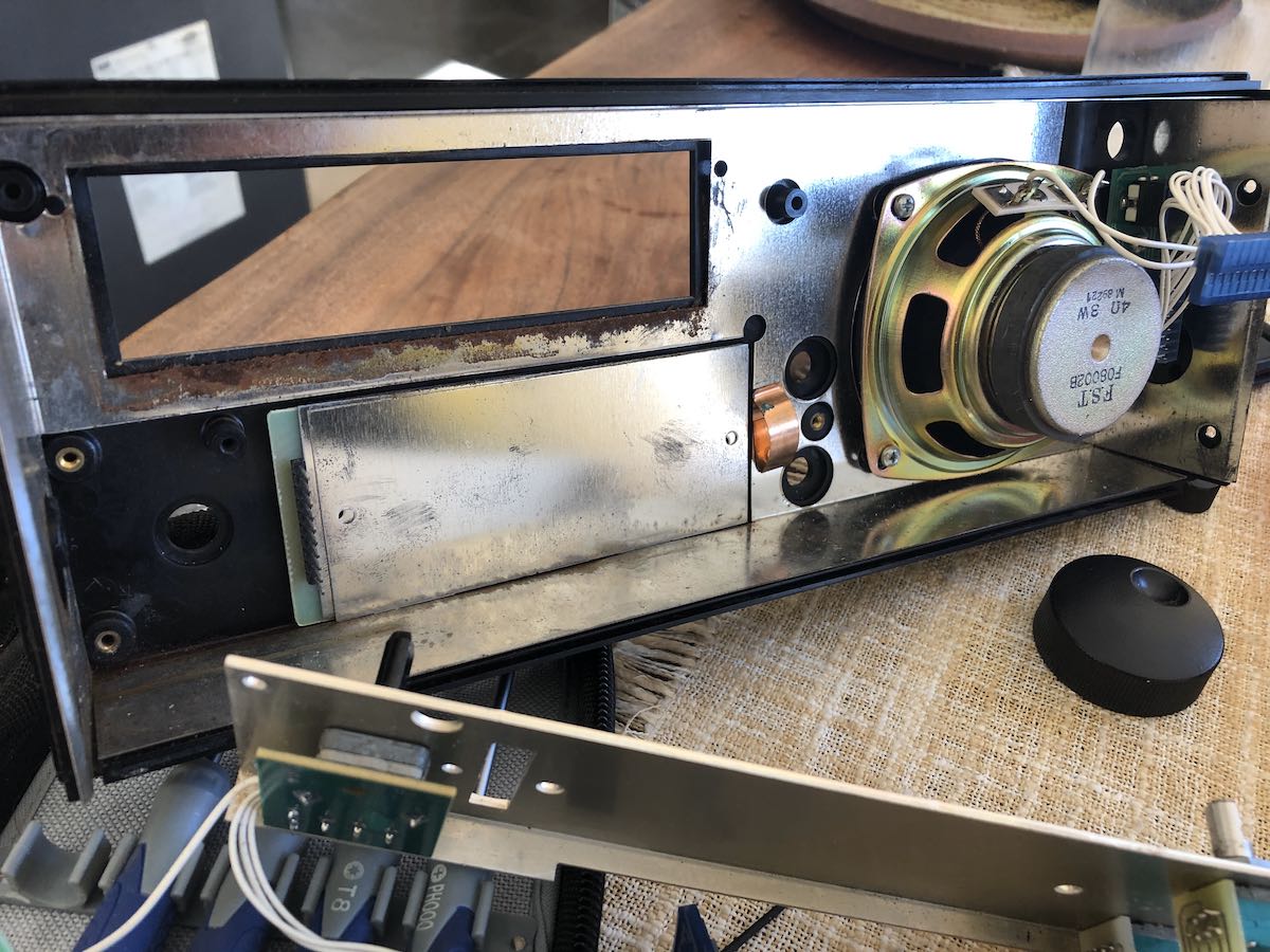
While I had everything apart, I cleaned the inside. At some point, a wee bit of moisture must have accumulated near the bottom of the keypad. I’m guessing this was condensation, because it was so minimal and so localized.
I replaced out the old keypad with the new one. Should you ever do this procedure, take note that the keypad has holes that line up with dimples on the back of the SW8 face place–the keypad circuit board also has holes that line up with dimples on the back of the rubber keypad. Lining these up will insure a correct fit.
I then re-assembled the faceplate boards and reconnected it to the body of the radio. Unfortunately, one can’t really test to see if the replacement works until all of the boards have been re-connected and re-assembled–a good 10-15 minute process.
 I tested the keypad and quickly discovered that number 9 and the bottom row of buttons were still a little flaky. After a little head scratching, it then dawned on me (after pulling the radio apart and reassembling it twice more!) that maybe part of the problem was left-over carbon/dust on the keypad circuit board.
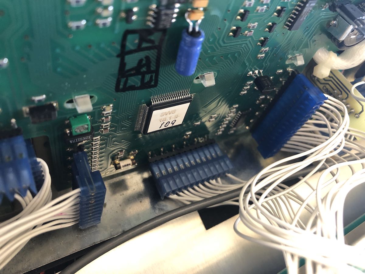
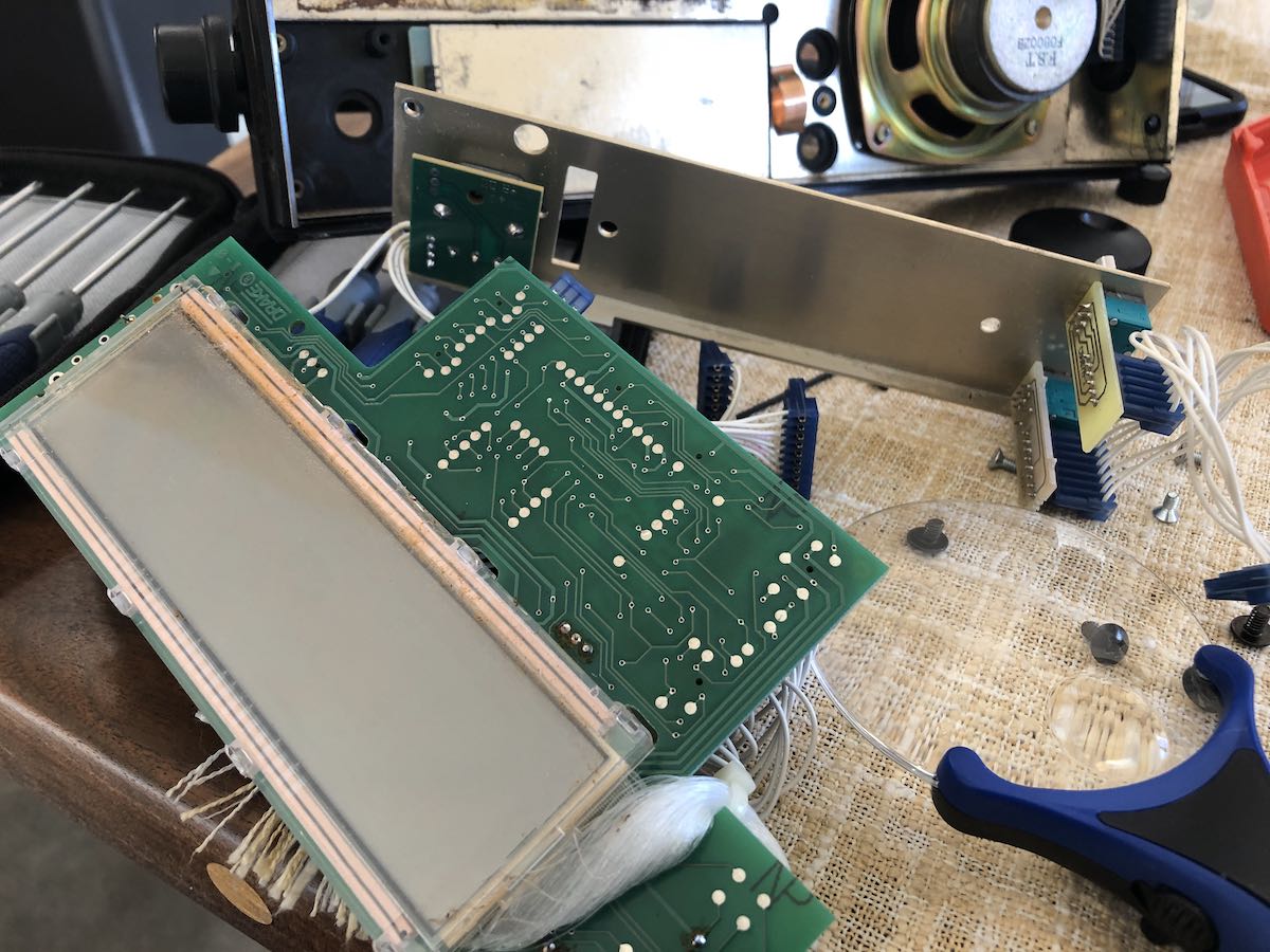
I disassembled the radio again and carefully cleaned the keypad circuit board with some DeOxit (a radio enthusiast’s best friend).
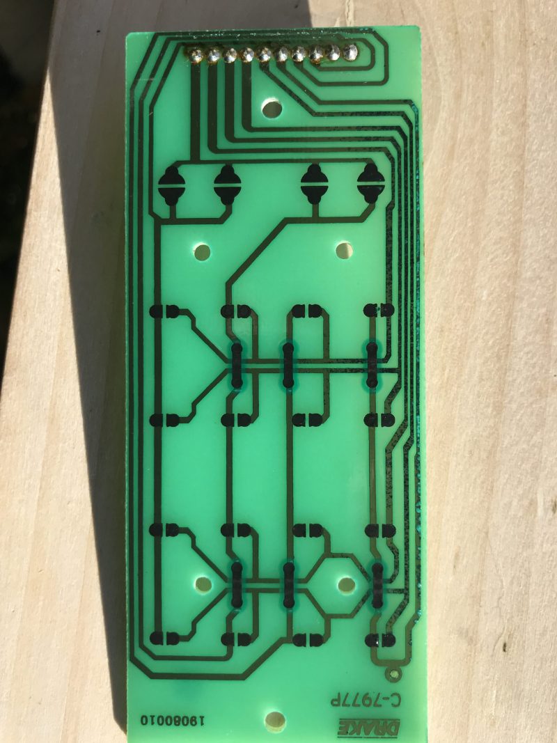 Through a closer inspection of the board, I could see that some of the traces on the bottom of the board had corrosion. That really worried me because I’m not entirely sure how I could mend traces. I tested continuity, however, and they all passed.
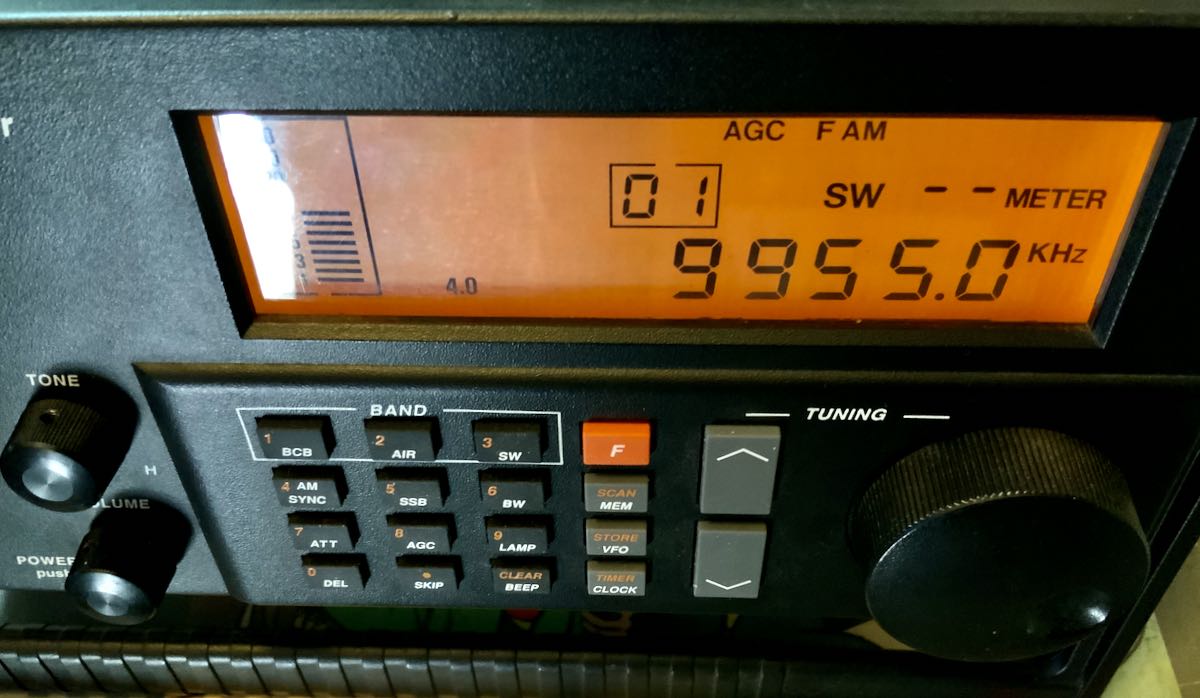
I reassembled the SW8 for the fourth or fifth time, tested it, and the keypad performed perfectly! Woo hoo!
Not only am I incredibly pleased that I was able to sort this out on my own, but now I can dissemblable and reassemble the SW8 with the speed of an Indy pit crew.
I’m still a little concerned about those traces on the keypad circuit board and the new keypad’s overall longevity, but at least I’ve got the SW8 back in tip-top shape and on the air for now. I’ll explore a work-around if these parts ever fail again.
I do love this receiver and now have it set up in the shack where I can do some proper armchair SWLing.
Do you have an SW8?
I’m curious if any SWLing Post readers have an SW8 and especially if you’ve had to replace your keypad. Please comment!