Category Archives: Radio Modifications

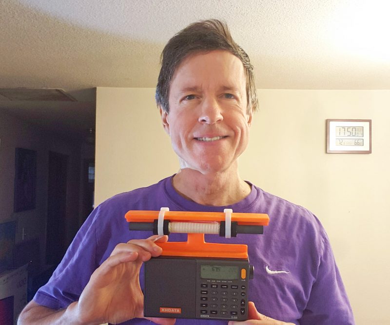
Gary DeBock’s XHDATA D-808 loopstick model

Many thanks to SWLing Post contributor, Gary DeBock, who shares the following:

The 7.5 inch (19cm) loopstick XHDATA D-808 model was designed to be the ultimate AM-DXing (or Longwave DXing) travel portable, and can be built for a construction cost of around $30 US. It has already been used by numerous DXers to track down transcontinental and transoceanic AM-DX during overseas travel, and the orange plastic loopstick frame allows full operation of the whip antenna for FM and Shortwave reception.

The modification procedure isn’t difficult, and the full construction article is posted at

https://dreamcrafts.app.box.com/s/5d0pi85jfptgmrj4pd0jsmaybgb6gteh

A video demonstration of its daytime DX performance (compared to the stock model) has been posted on YouTube:

Build one, and join the fun! 🙂

Many thanks for sharing this, Gary! Your ultralight DXing creations are simply amazing!

Spread the radio love

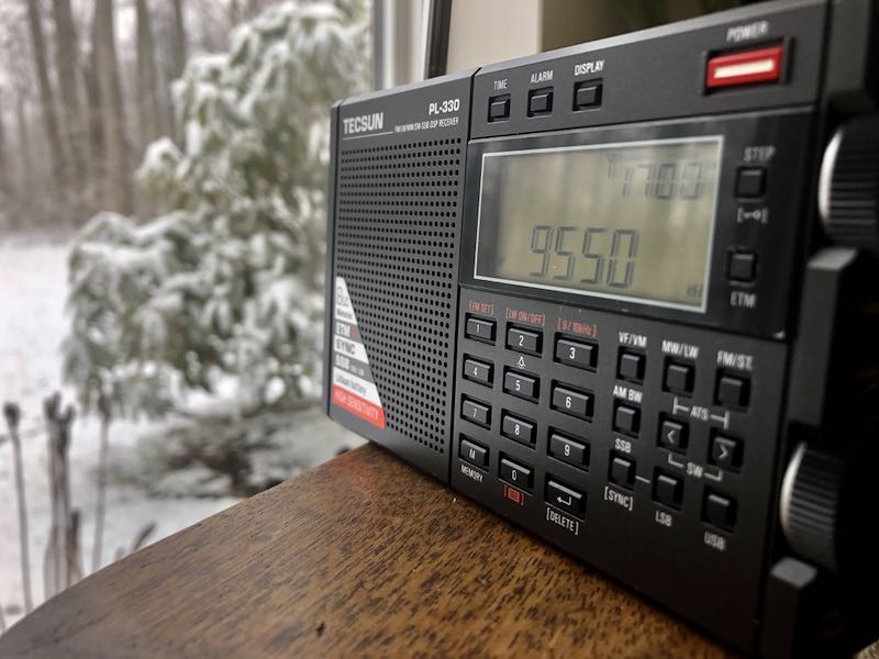
Tecsun PL-330 tip: Using the telescopic antenna for the LW & MW bands

Many thanks to SWLing Post contributor, Mad Radio DXer, who writes:

Hi,

I want to let you & your readers know of a Tecsun PL-330 trick that I saw mentioned in the comments section of your blog some time ago which does not seem to have a lot of awareness. This is for using the telescopic antenna for the LW & MW bands, & it works for the 3305 version of the PL-330 which I understand is the export version. The original comment I saw said this also works for the Chinese version of the PL-330, before firmware 3305.
It is very easy to do & instructions are the following…

1. Turn on the radio.
2. Select either the MW or LW band.
3. Press the number 3 key down for a few seconds, until the display shows “CH-S”.
This means the MW & LW bands can now be received with the telescopic antenna.
4. To use the ferrite bar again, press the number 3 key until “CH-A” appears on screen.

I also did a YouTube video showing this trick in action…

This reminds me of the trick used for the Degen DE1103 PLL version which allows reception of the telescopic antenna for the MW band. However, in my opinion this is much easier to use on the PL-330 than the DE1103 PLL which could be very fiddly. Also this trick is most effective on the LW band, as I find Chinese portables are usually very weak on this part of the band which is good news for LW DXers. I hope you & everyone reading find this trick very useful & that it works.

Thank you so much for the excellent tip!

Spread the radio love

Chuck’s re-capped GE Superadio II might set a new AM BCL benchmark

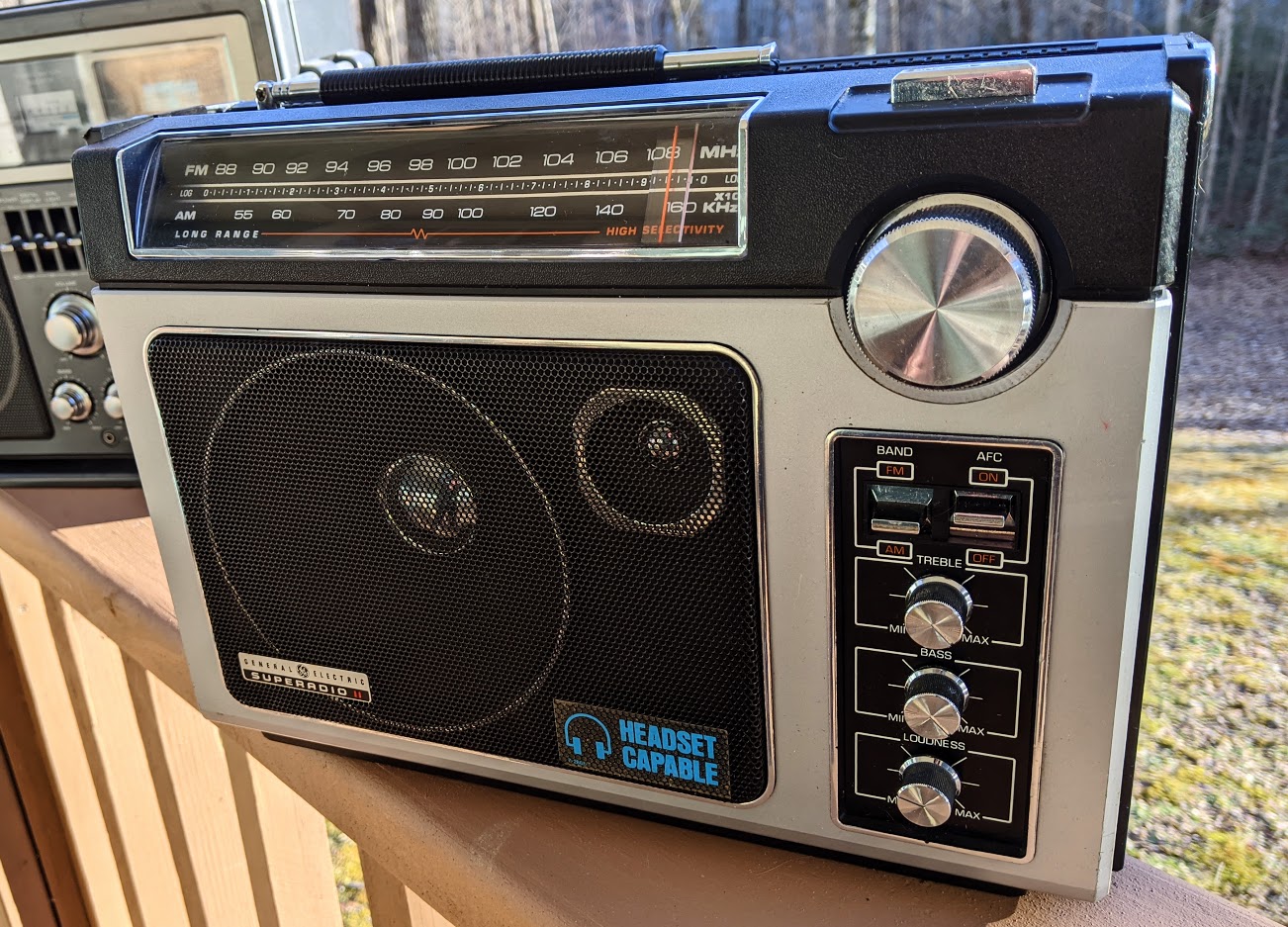
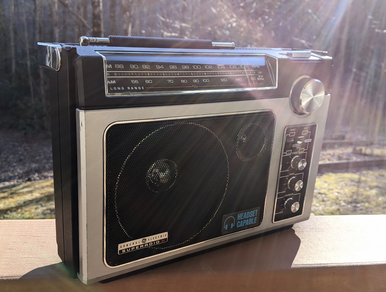
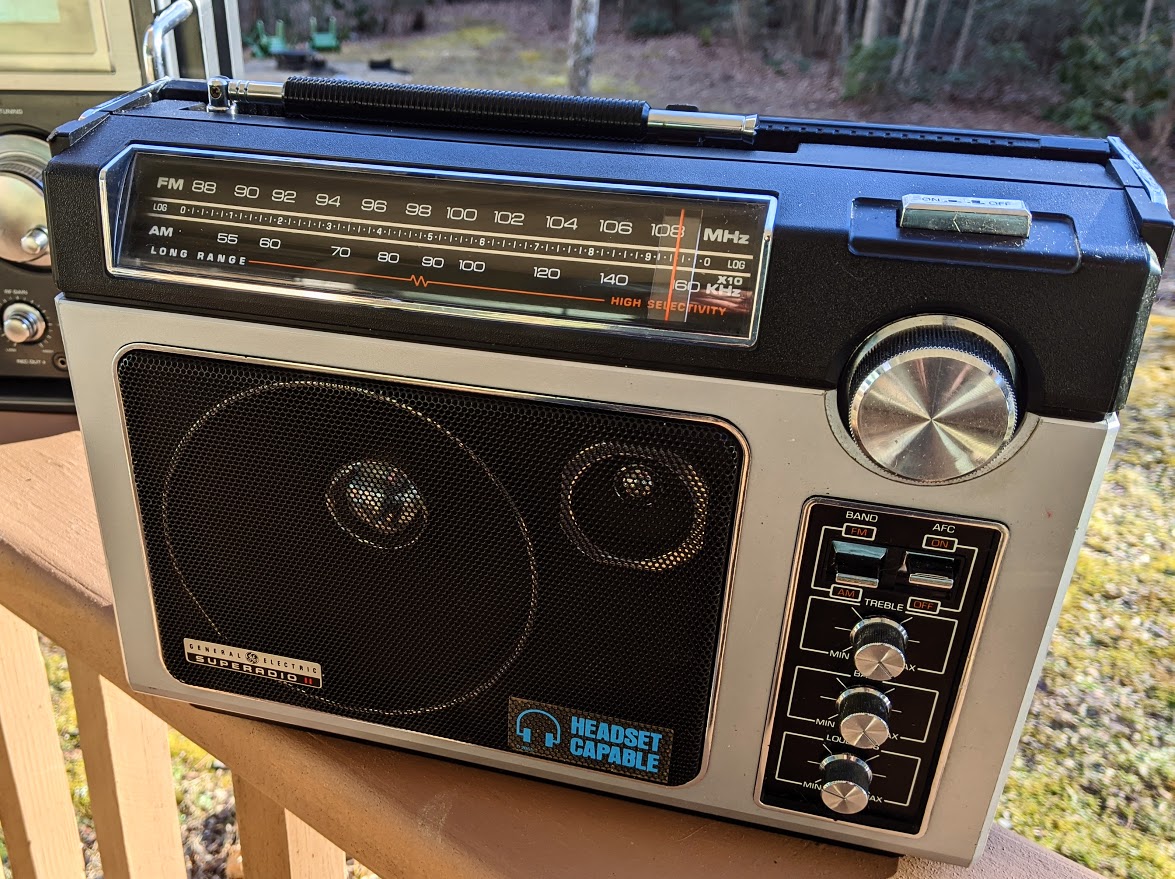
I recently took delivery of a better-than-new classic solid-state portable broadcast receiver: the venerable GE Superadio II.

This Superadio II was generously given to me by SWLing Post contributor, Chuck Rippel (K8HU), who has–in his spare time–been re-capping and restoring all three of the GE Superadio series models and bringing them back to life. Chuck wanted to send me one of the units he’d recently finished, knowing that it might help me when doing AM reception evaluations. He insisted “no strings attached.”

Besides thank you, all I can say is…

Wow–!

Note angels singing in the background.

When I received the Superadio II a week or so ago, I removed it from the box and it looked brand new; even sporting the original “Headset Capable” grill sticker.

This is a case, however, of a refurbished radio likely out-performing the original.  Here’s a list of the main modifications:

  • All of the original dry capacitors replaced with Nichicon Audio Grade components
  • FM AFC and AM and FM IF and RF sections have been aligned
  • Rebuilt the volume control

I’m sure there are other modifications Chuck didn’t mention.

Chuck told me each radio takes a full day to restore. Some of the alignment, rebuilding, and re-capping is surprisingly tricky and varies with each of the three models. Why is he doing this?

Chuck told me, “My enjoyment comes from giving these radios a new lease on life.”

A new lease on life, indeed!

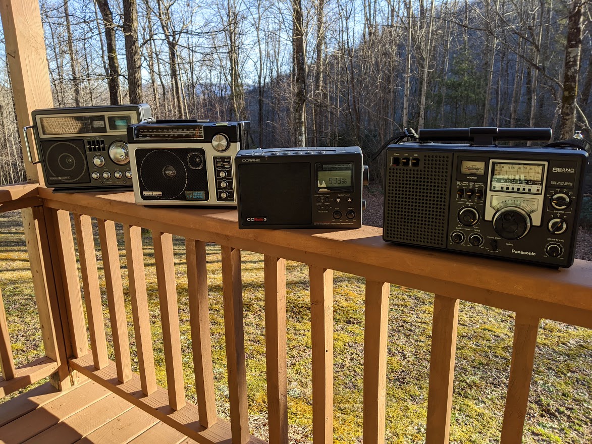
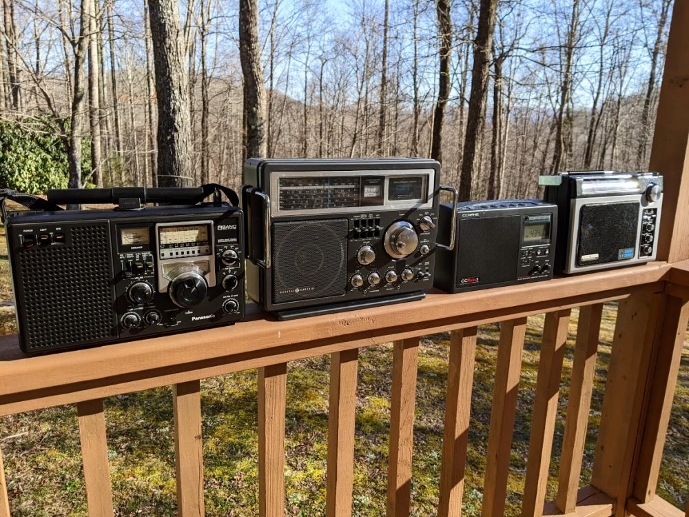
Last weekend, we had a break in the weather–and I had a short break in my schedule–so I took the GE Superadio II, GE 7-2990A, C.Crane CCRadio3, and Panasonic RF-2200 outdoors for some fresh air.

It was late afternoon and, frankly, I didn’t have the time to do a full comparative session, but having spent the better part of an hour tuning around and comparing the characteristics of each radio, I decided to make a short video to share.

The video features the GE Superadio II, but I speak to some of the pros and cons of each model. Keep in mind, this is very much a casual/informal comparison:

Click here to view on YouTube.

The SR-II not only has the best audio fidelity in this bunch, but it’s also extremely stable and has no noise floor to speak of. No doubt, this is the result of those Nichicon Audio Grade components and a skilled technician.

Side note: Chuck is well-known in the radio world because he used to restore the Collins R390A which must be one of the most mechanically-complicated receivers ever made.

I haven’t even properly tested the SR-II on FM yet because I couldn’t pull myself away from the mediumwave dial that afternoon!

I asked Chuck if he would consider refurbishing GE Superadios for other people and I think he would.  If interested, contact me and I’ll put you in touch. Else, Chuck might leave details in the comments section of this post.

He does currently have a restored GE Superadio II on eBay. I just checked and in his listing, you’ll see a full description of the modifications made.

Click here to view on eBay.

Chuck, thank you once again for sending me this SR-II. It’ll become a permanent addition here at SWLing Post HQ. Again, I’m simply amazed at the audio fidelity of this 1980s era receiver. Honestly, I don’t think there’s anything made today that can even compare.

And thanks for doing your bit to refurbish these classic portables!

Spread the radio love

Installing the Belka-DX DSP speaker option

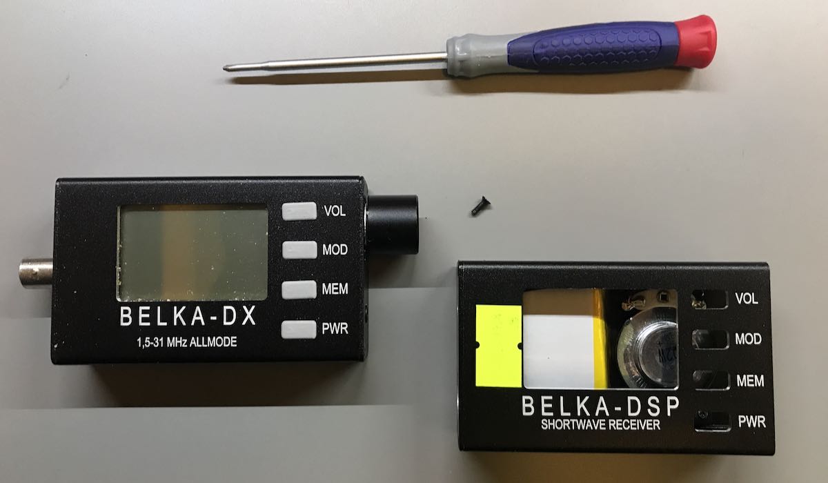
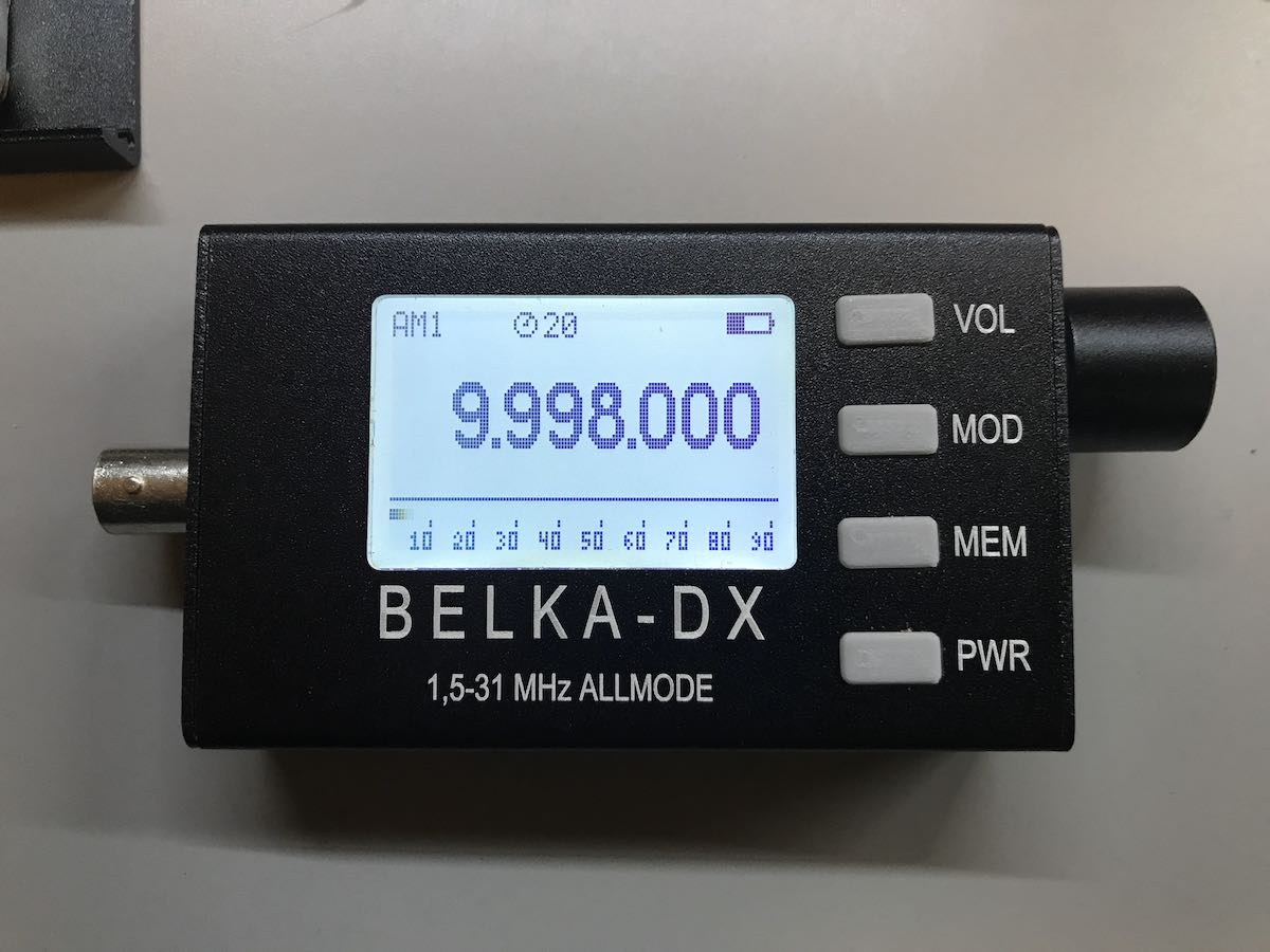
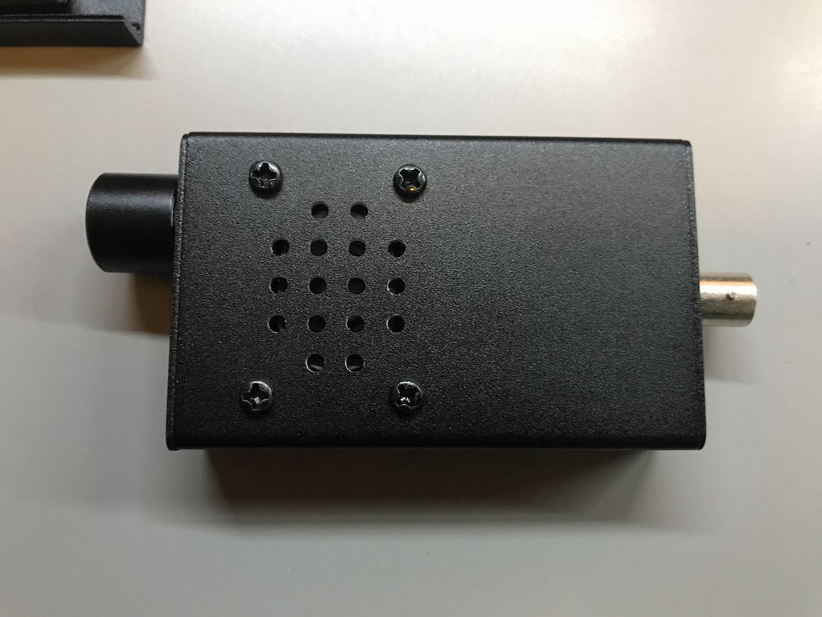
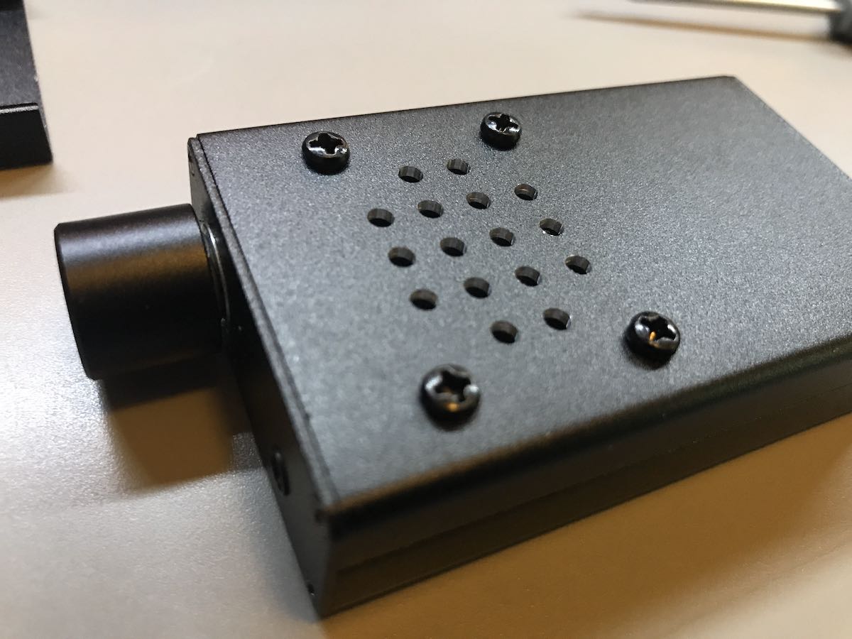
This month, I received my Belka DX speaker option in the post and recently did this very simple install. All it really requires is a small Phillips-Head screwdriver and maybe 10 minutes of time.

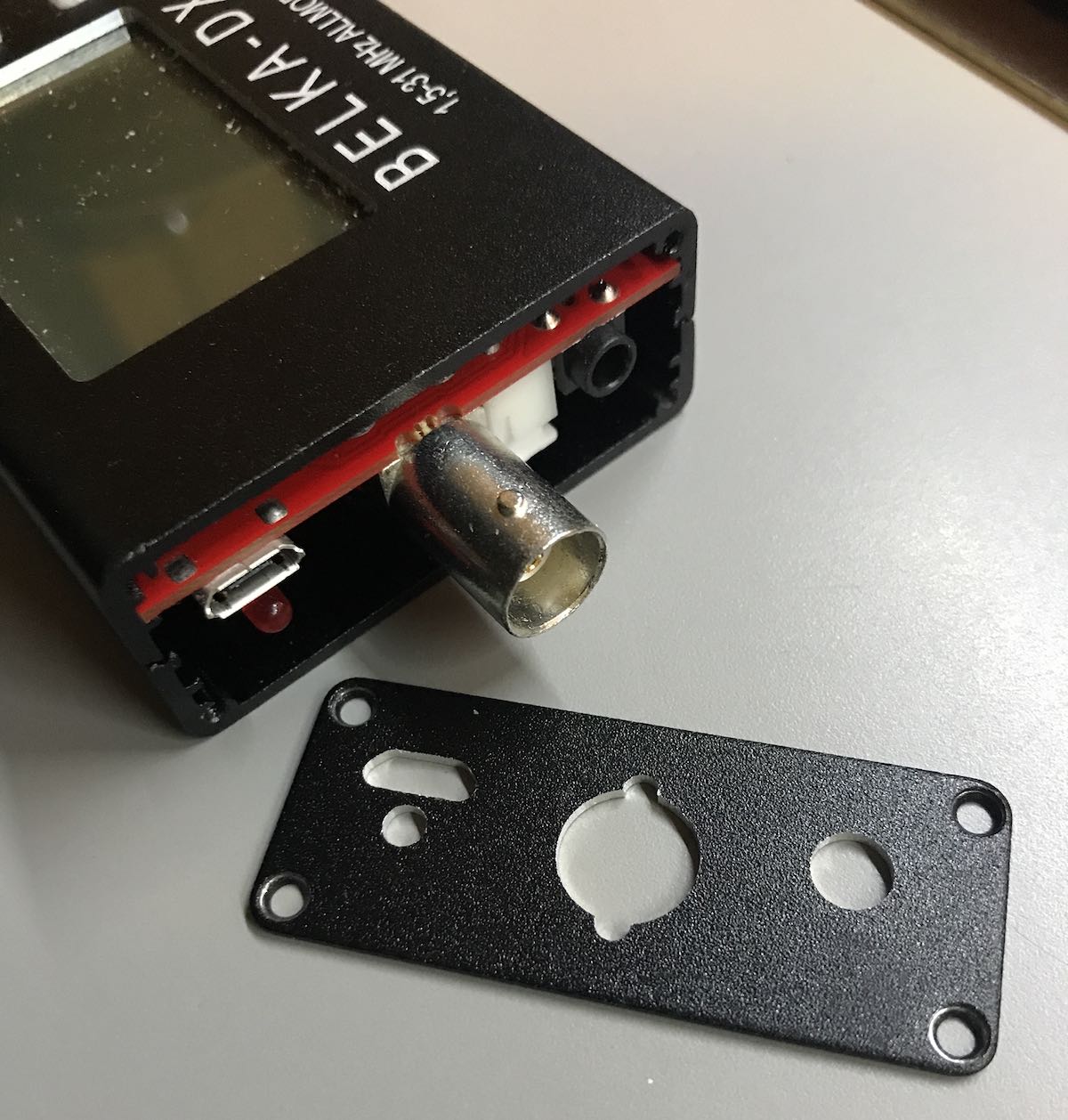
You start by removing the four screws holding on the left side panel. The side panel easily slides off over the BNC connector.

You then remove the bottom two screws of the right side panel. There’s no need to remove the top two screws as you will not remove this panel or the encoder knob. After removing the bottom two screws, carefully pull the bottom panel off.

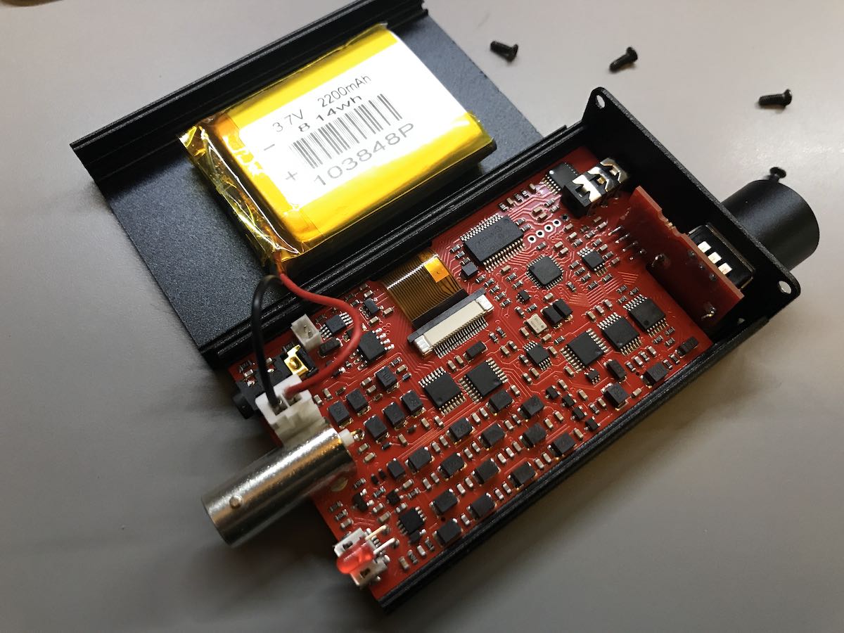
The battery is connected to the Belka-DX DSP board with an end that’s easy to unplug.

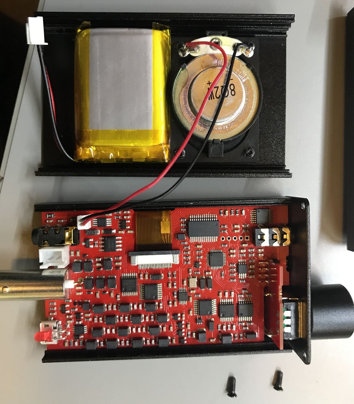
Simply unplug the battery, and plug in the new (smaller) battery of the speaker panel in the same position.

The speaker on the new panel needs to be connected, of course. In the photo above, you can see where it attaches to the Belka DX board (next to the headphone port).

Once you’ve plugged in the new battery and speaker, attach the new bottom panel to the radio, making sure the speaker and battery wires fold in properly. After you’ve put the two right panel screws in, reattached the left panel with four screws and the installation is complete!

The speaker is quite small, of course, but very functional. I love the fact that I no longer need a set of earphones or external amplified speaker to listen to the Belka DX.

I was concerned that the speaker would be too small to be functional and that the smaller battery in combination would dramatically decrease listening time per charge.

Not the case.

Although I haven’t done a continuos battery longevity test with the volume at a constant moderate level, it will power the radio for extended listening sessions. Of course this teeny internal speaker isn’t going to deliver room-filling audio, but has exceeded my expectations and certainly does the trick!

If you own a  Belka-DX DSP receiver, this is a worthy, affordable upgrade. The great thing is, you can always swap out the covers easily if you need the larger battery capacity during travels or DXpeditions.

Click here to purchase the Belka DX speaker option on Alex’s site. 

Spread the radio love

Replacing the keypad on my Drake SW8

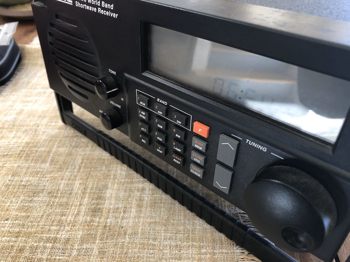
In 2019, I made an impulse purchase: a Drake SW8 tabletop receiver. As I mentioned previously, I’d always wanted an SW8. My buddy, David Goren, recommended this receiver ages ago, Each time I’ve stayed at his home in Flat Bush, he magically made an SW8 available as my bedside radio in the guest room. (That’s hospitality!)

After receiving my SW8 and putting it on the air, I realized it suffered from a common problem found in Drake receivers: a flaky keypad. Several of the buttons didn’t work reliably, or they made multiple contacts on each push, or they didn’t work at all.

What happens is, over time, the black carbon dot on the back of each pad on the rubber membrane simply wears out and no longer makes reliable contact. I believe a number of Drake receivers of the era used the same keypad style (though configured differently).

The seller didn’t realize this when he sold it to me and, frankly, I felt I got a pretty good deal regardless, so never bothered him about it.

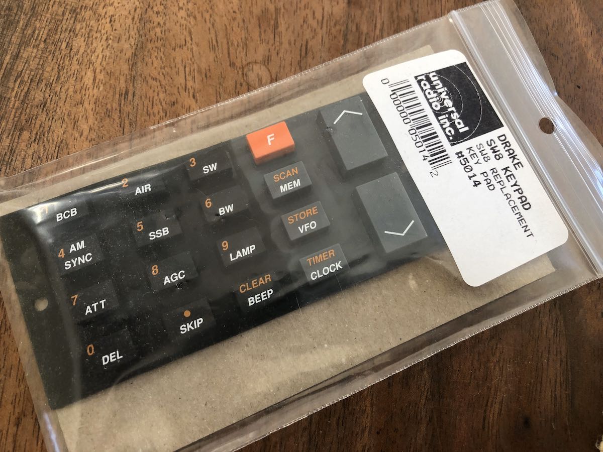
A couple months later, I found out that Universal Radio uncovered a box of new old stock SW8 replacement keyboards, so I ordered one.
2020 got a little out of hand and I put off making the repair. I didn’t want to trouble my buddy, Vlado, who could have done this in his sleep. I knew I could handle a parts replacement as long as I didn’t need to de-solder the keypad from a circuit board (as one does with the SW2, I understand).

Tuesday, I cleaned off one of my radio shelves and found the replacement keypad. I looked at the SW8 and knew it was time to get’er done!
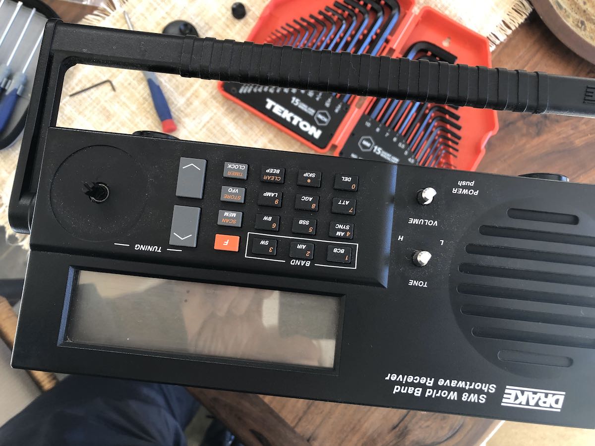
I first removed the encoder, volume, and tone knobs.
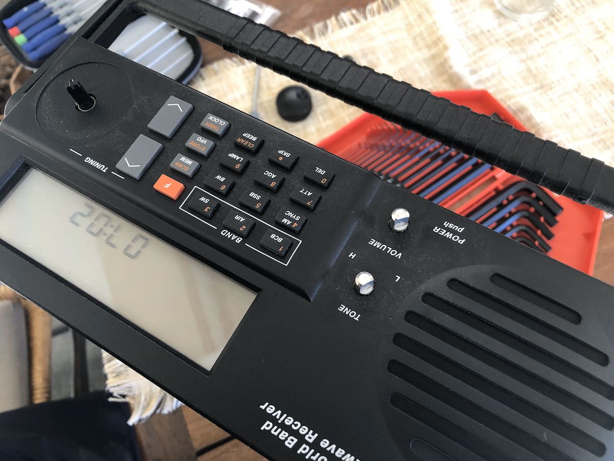
Next, I removed the top cover which is attached with five screws.
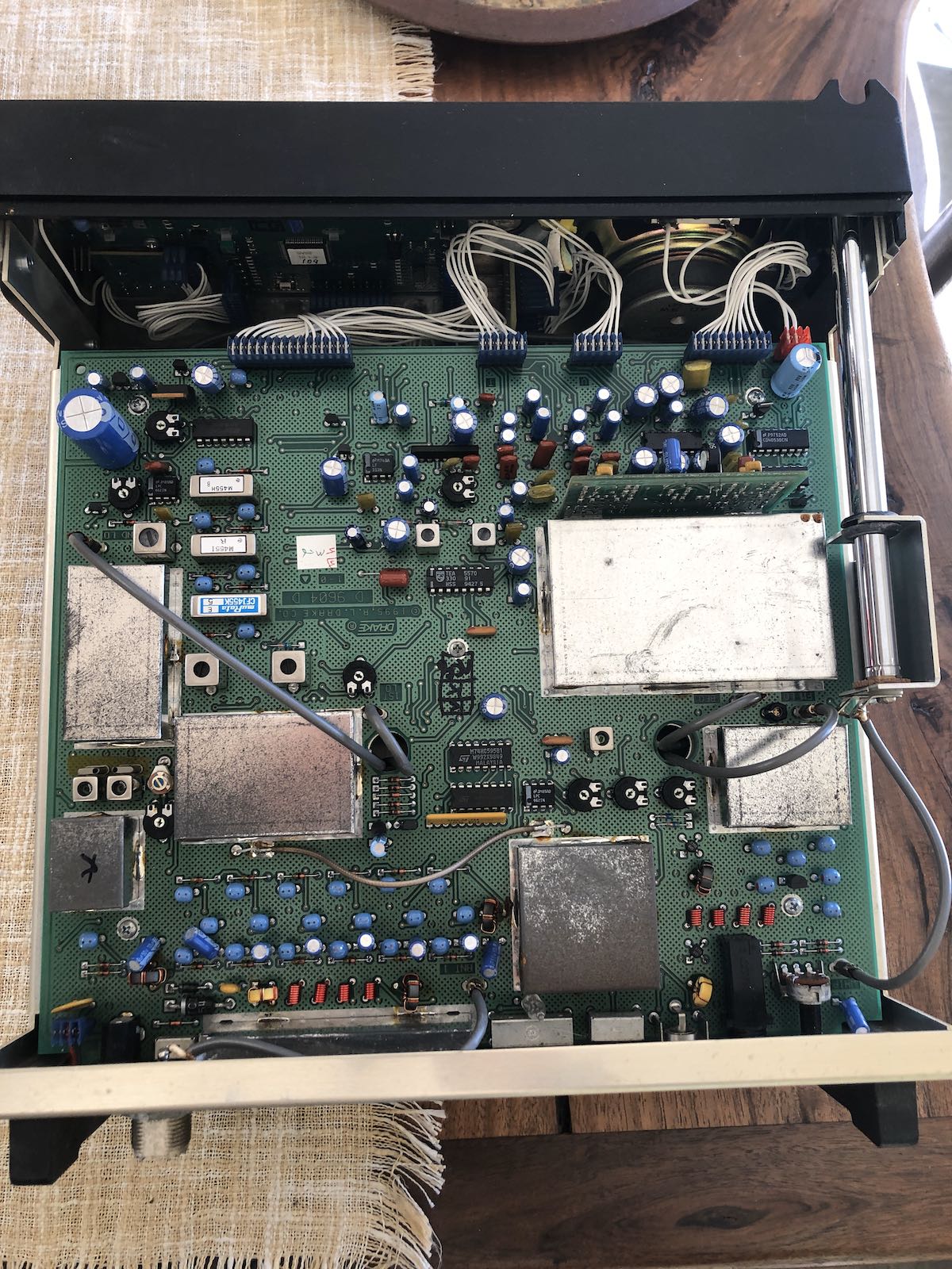
There are a number of multi-pin plugs that attach the front faceplate section to the main body of the radio.
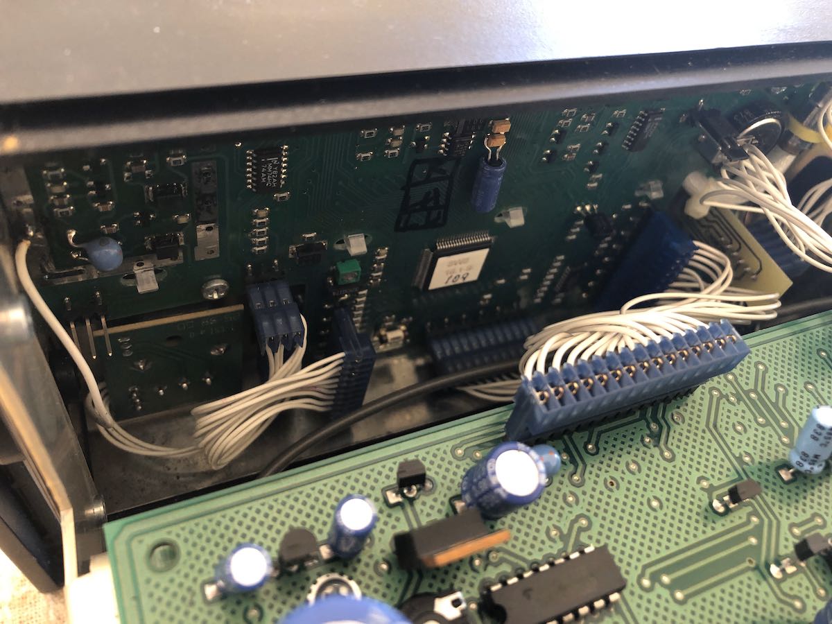
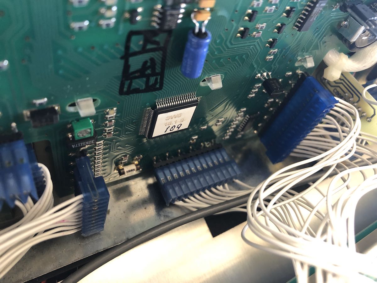
I carefully removed all of them and noted their positions (taking photos at each stage really helps).
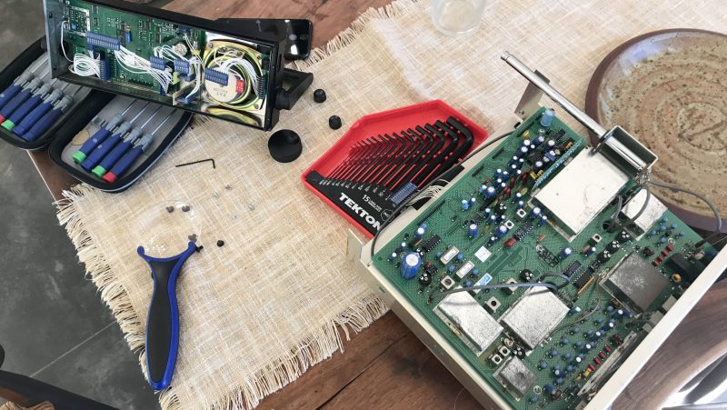
I quickly discovered that the keypad was under at least two more board layers.
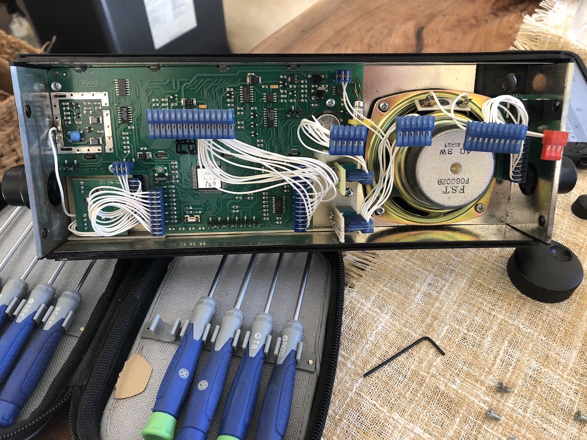
I removed the main board which is held in place with three screws, then the board underneath which is also held in place with three screws.
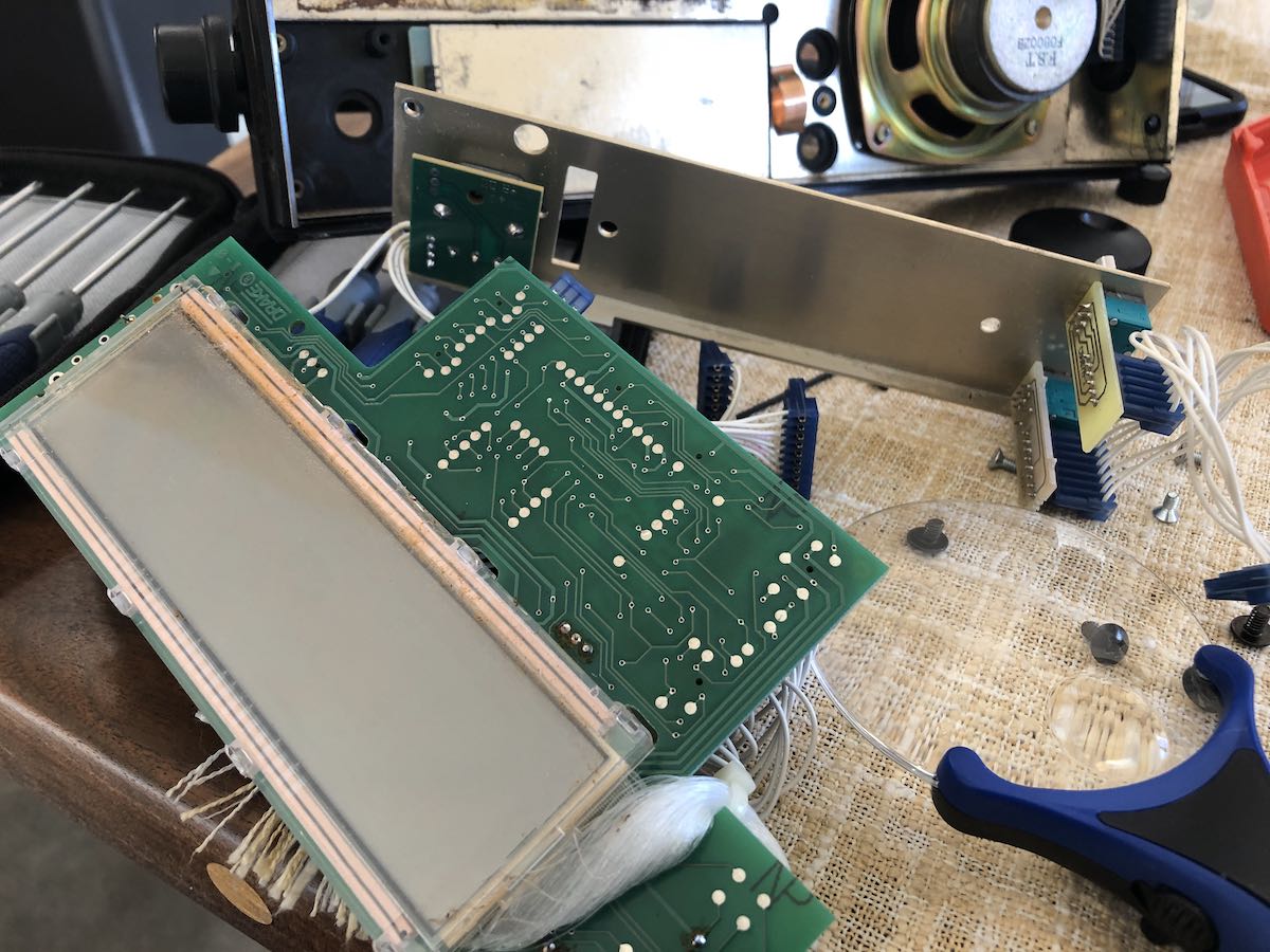
To my surprise, the keypad, circuit board and two metal plates (in that order) are held in place with compression from the last board layer.
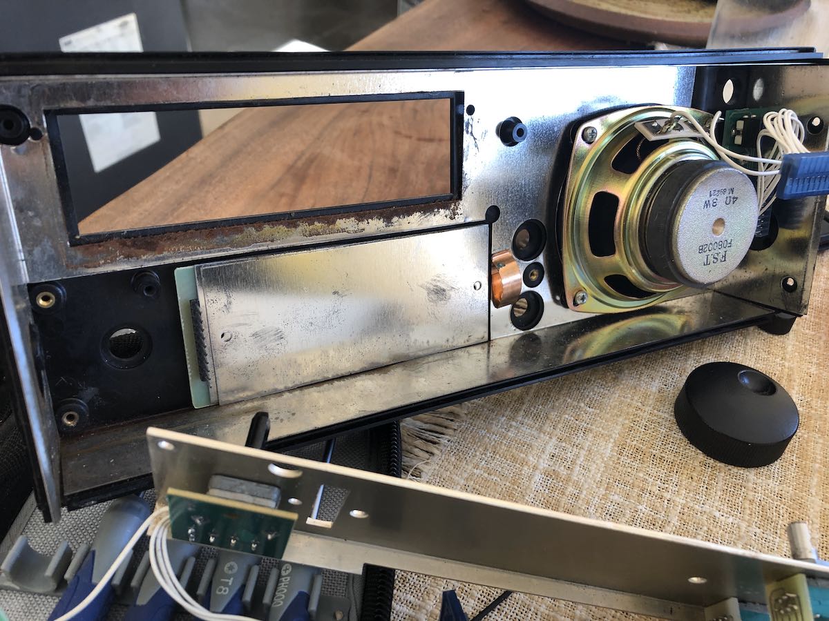
The keypad, circuit board and metal plates fell out quite easily.
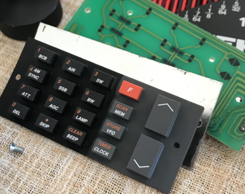
While I had everything apart, I cleaned the inside. At some point, a wee bit of moisture must have accumulated near the bottom of the keypad. I’m guessing this was condensation, because it was so minimal and so localized.

I replaced out the old keypad with the new one. Should you ever do this procedure, take note that the keypad has holes that line up with dimples on the back of the SW8 face place–the keypad circuit board also has holes that line up with dimples on the back of the rubber keypad. Lining these up will insure a correct fit.

I then re-assembled the faceplate boards and reconnected it to the body of the radio. Unfortunately, one can’t really test to see if the replacement works until all of the boards have been re-connected and re-assembled–a good 10-15 minute process.
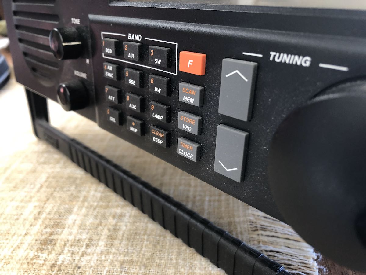
I tested the keypad and quickly discovered that number 9 and the bottom row of buttons were still a little flaky. After a little head scratching, it then dawned on me (after pulling the radio apart and reassembling it twice more!) that maybe part of the problem was left-over carbon/dust on the keypad circuit board.

I disassembled the radio again and carefully cleaned the keypad circuit board with some DeOxit (a radio enthusiast’s best friend).
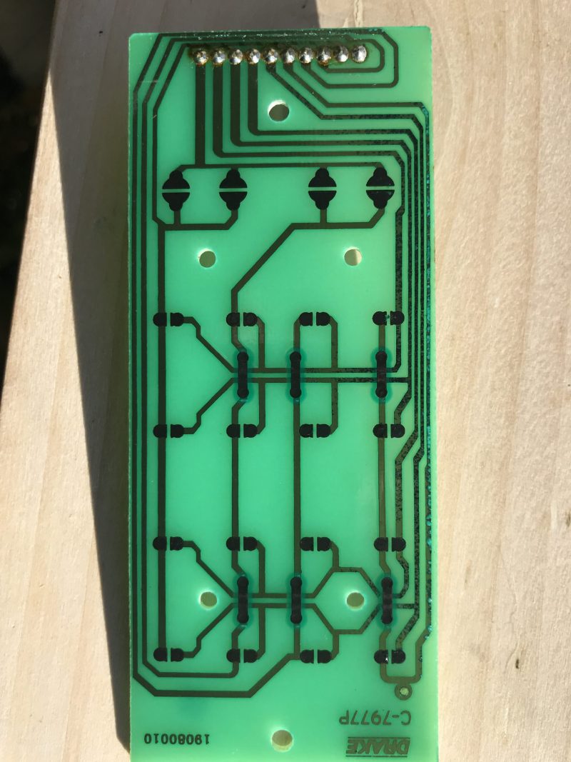
Through a closer inspection of the board, I could see that some of the traces on the bottom of the board had corrosion. That really worried me because I’m not entirely sure how I could mend traces. I tested continuity, however, and they all passed.

I reassembled the SW8 for the fourth or fifth time, tested it, and the keypad performed perfectly!  Woo hoo!
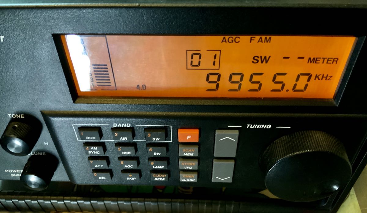
Not only am I incredibly pleased that I was able to sort this out on my own, but now I can dissemblable and reassemble the SW8 with the speed of an Indy pit crew.
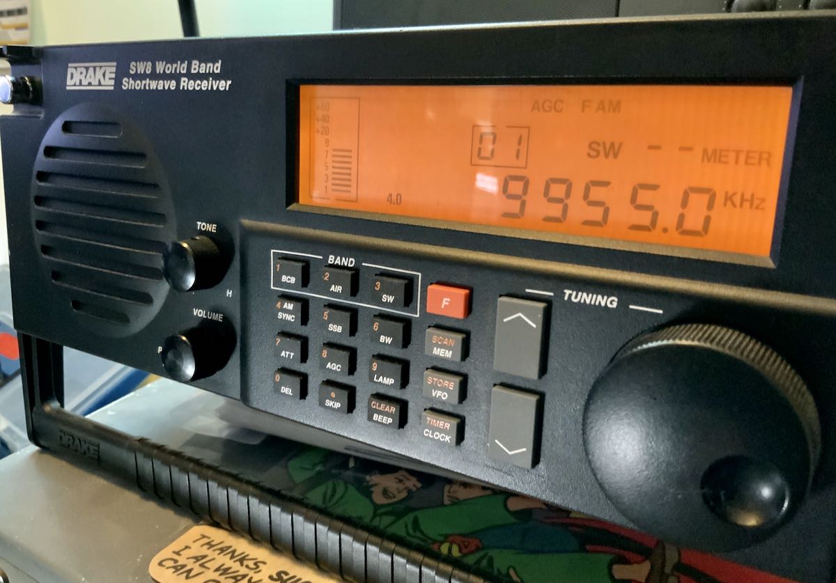
I’m still a little concerned about those traces on the keypad circuit board and the new keypad’s overall longevity, but at least I’ve got the SW8 back in tip-top shape and on the air for now. I’ll explore a work-around if these parts ever fail again.

I do love this receiver and now have it set up in the shack where I can do some proper armchair SWLing.

Do you have an SW8?
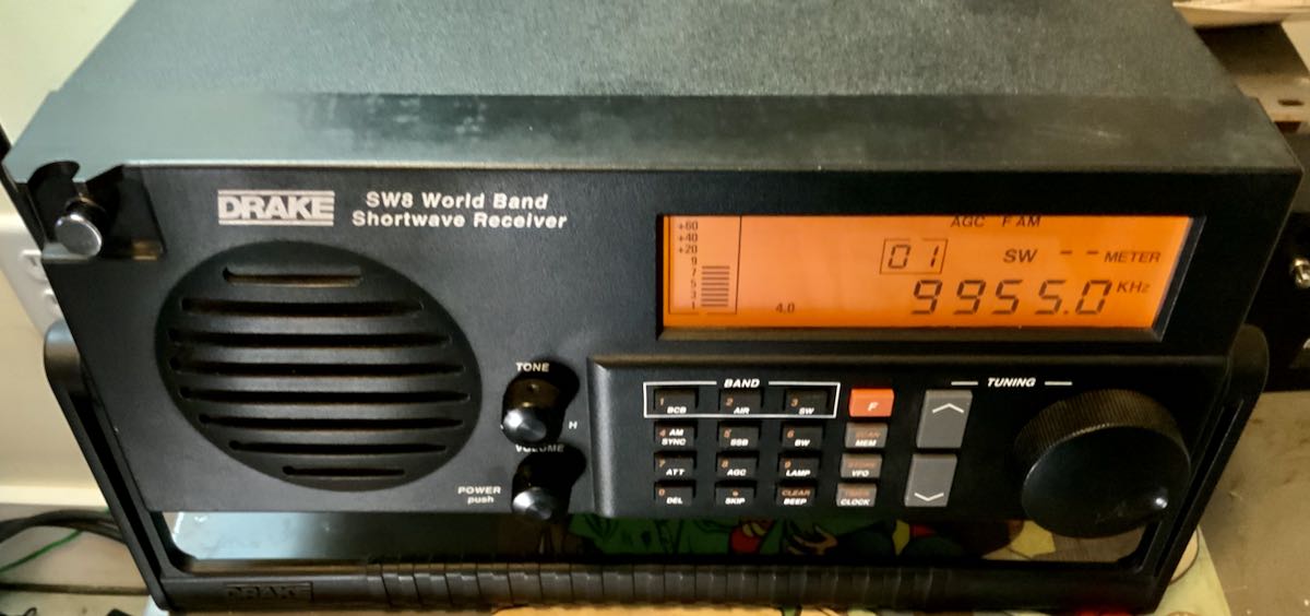
I’m curious if any SWLing Post readers have an SW8 and especially if you’ve had to replace your keypad.  Please comment!

Spread the radio love

Upgrading my Yaesu FT-817 transceiver with the G7UHN rev2 Buddy board

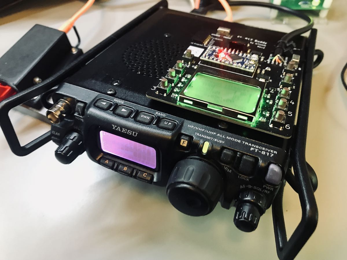
Last August, SWLing Post contributor, Andy (G7UHN), shared his homebrew project with us: a genius companion control display for the venerable Yaesu FT-817 general coverage QRP transceiver.

Andy’s article caused me (yes, I blame him) to wax nostalgic about the popular FT-817 transceiver. You see, I owned one of the first production models of the FT-817 in 2001 when I lived in the UK.

At the time, there was nothing like it on the market: a very portable and efficient HF, VHF, UHF, multi-mode general coverage QRP transceiver…all for $670 US.

In 2001? Yeah, Yaesu knocked it out of the ballpark!

In fact, they knocked it out of the ballpark so hard, the radio is still in production two decades later and in demand under the model FT-818.

I sold my FT-817 in 2008 to raise funds for the purchase of an Elecraft KX1, if memory serves. My reasoning? The one thing I disliked about my FT-817 was its tiny front-facing display. When combined with the embedded menus and lack of controls, it could get frustrating at home and in the field.

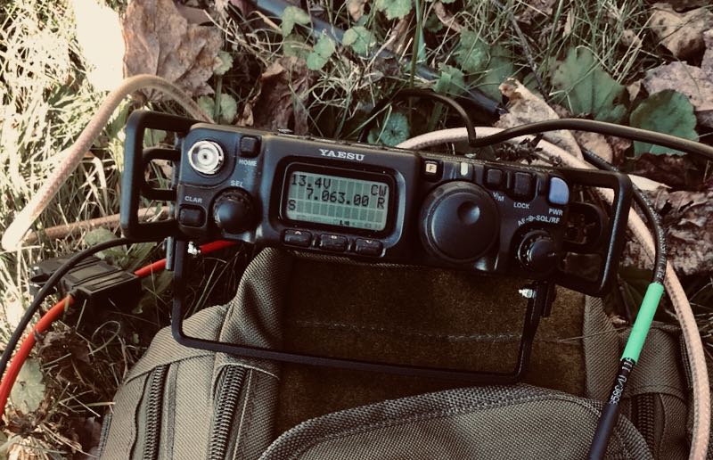
I mentioned in a previous post that I purchased a used FT-817ND from my buddy, Don, in October, 2020. I do blame Andy for this purchase. Indeed, I hereby declare him an FT-817 enabler!

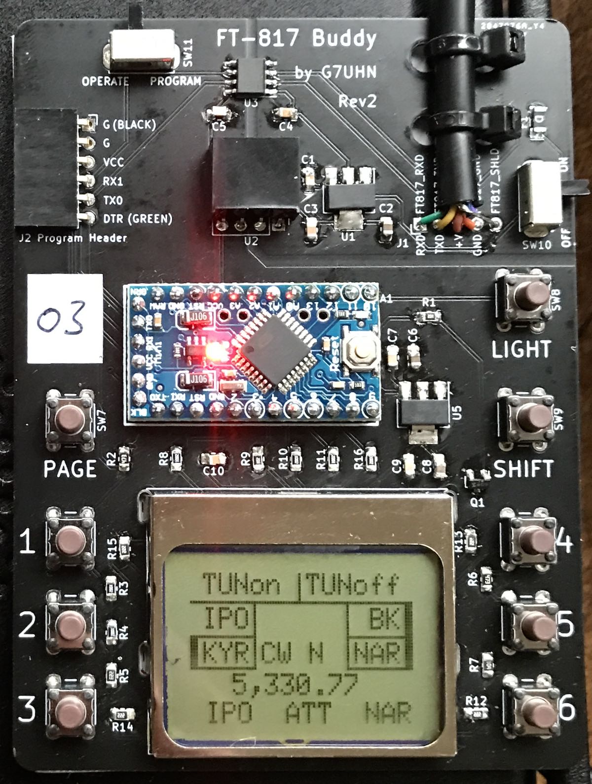
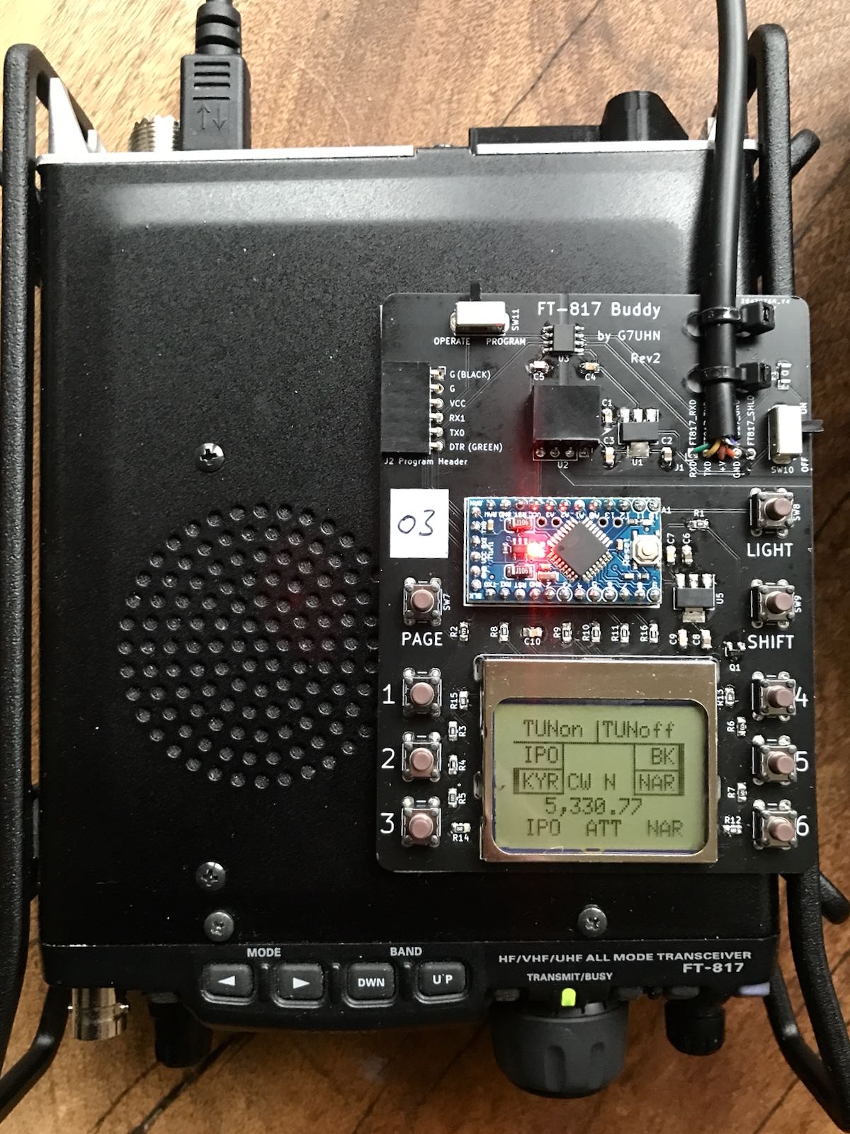
FT-817 Buddy board

When I told Andy about my ‘817ND purchase, he asked if I’d like to help him test the FT-817 Buddy board versions. How could I refuse?

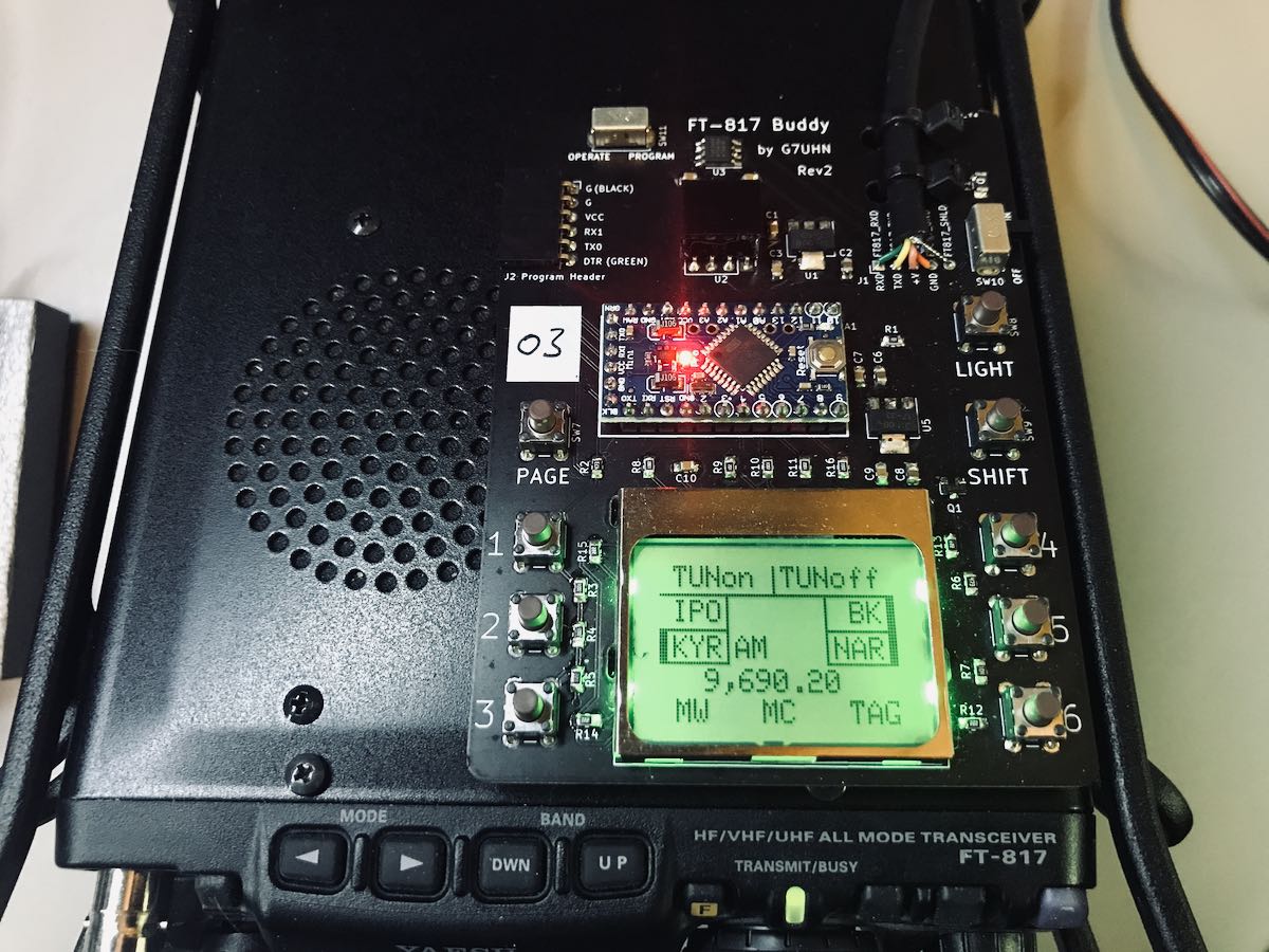
Andy sent me a prototype of his Version 2 Buddy board which arrived in late November. I had to source out a few bits (an Arduino board, Nokia display, and multi-conductor CAT cable). Andy kindly pre-populated all of the SMD components so I only needed to solder the Arduino board and configure/solder the cable. I did take a lot of care preparing and soldering the cable, making sure there was no unintentional short between the voltage and ground conductors.

Overall, I found the construction and programming pretty straight-forward. It helped that Andy did a remote session with me during the programming process (thanks, OM!). Andy is doing an amazing job with the documentation.

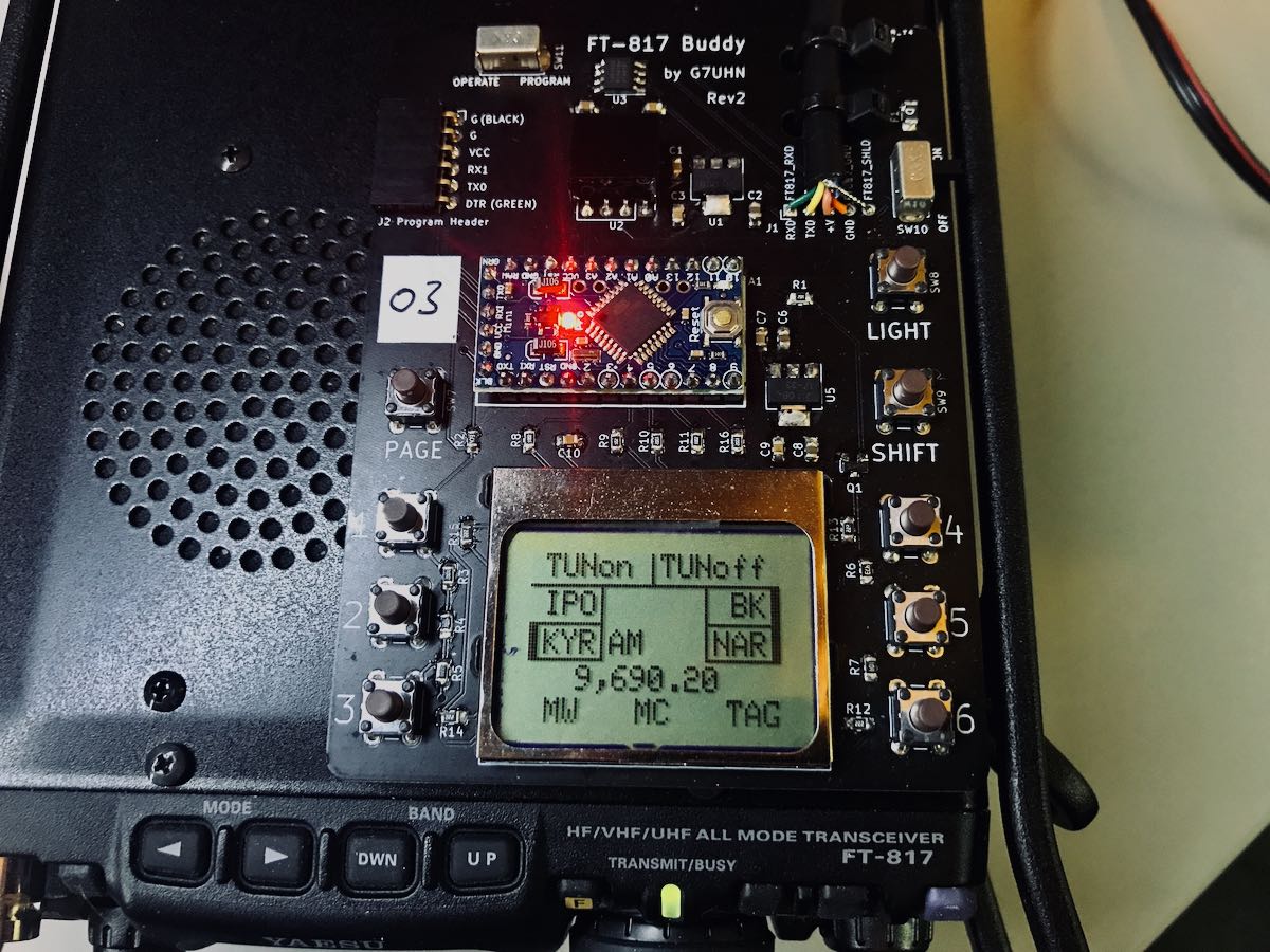
I do love how the board makes it easier to read the frequency and have direct access to important functions without digging through embedded menus. While there’s nothing stopping you from changing the program to suit you, Andy’s done a brilliant job with this since he’s an experienced FT-817 user.

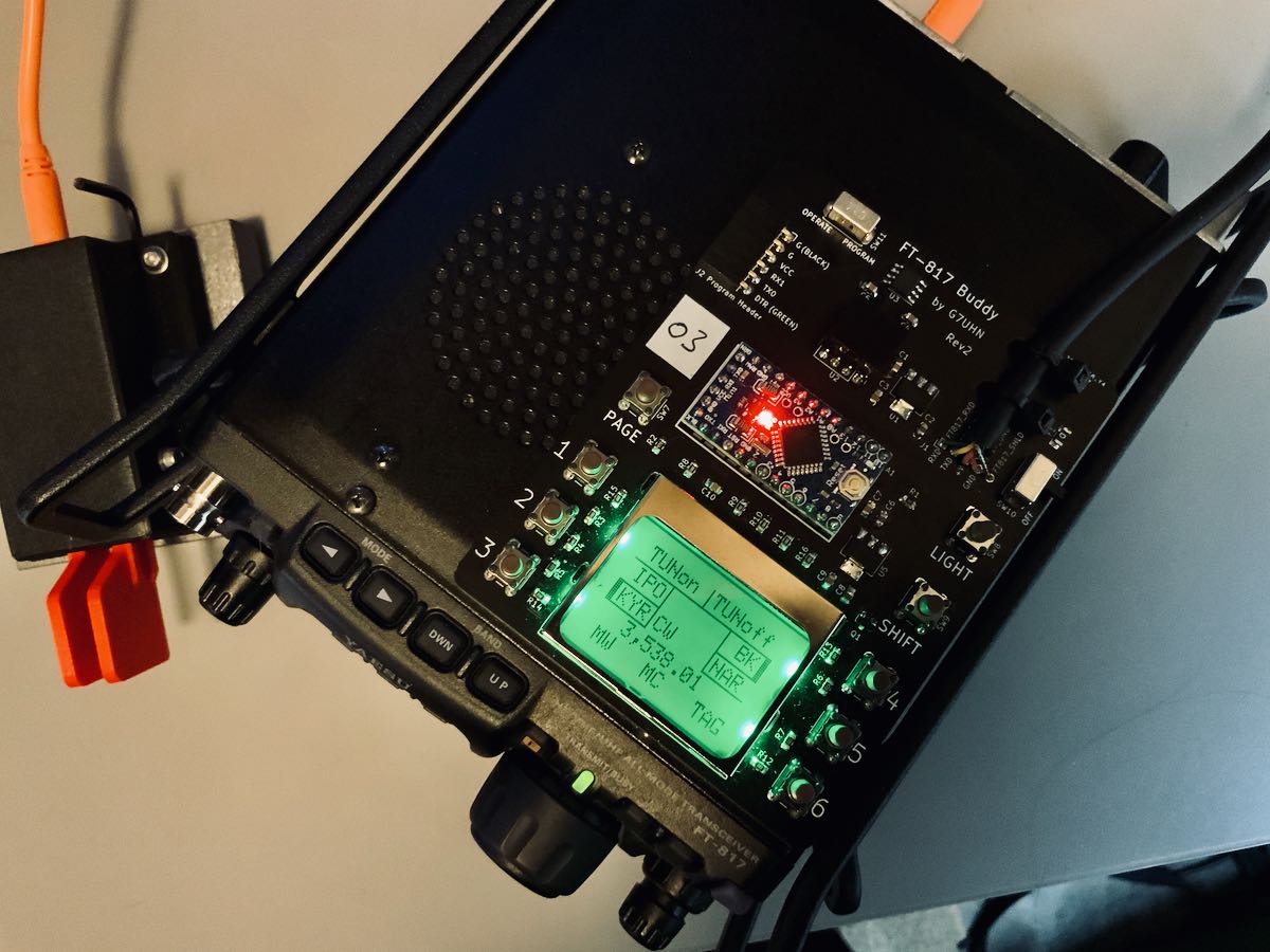
The Nokia display is very well backlit, high contrast, and easy very to read.

“Resistance is futile”

I mentioned on Twitter that, with the backlight on, the FT-817 Buddy makes my ‘817ND look like it was recently assimilated by The Borg.

Don’t tell any Star Trek captains, but I’m good with that.

Andy has a rev3 board in the works and it sports something that will be a game-changer for me in the field: K1EL’s keyer chip!

For more information about the FT-817 Buddy, check out Andy’s website. At time of posting, it’s not available yet, but as Andy says, “it’s nearly there!”

Of course, we’ll keep you updated here as well. Many thanks to Andy for taking this project to the next level. No doubt a lot of FT-817 users will benefit from this brilliant project!
Spread the radio love

Radio Waves: Hammarlund Legacy, FM Radio Using Arduino, VOA Report on Bias, ARISS SSTV Event, and Geminids

Radio Waves:  Stories Making Waves in the World of Radio

Because I keep my ear to the waves, as well as receive many tips from others who do the same, I find myself privy to radio-related stories that might interest SWLing Post readers.  To that end: Welcome to the SWLing Post’s Radio Waves, a collection of links to interesting stories making waves in the world of radio. Enjoy!
Many thanks to SWLing Post contributors Trevor, Dan Robinson, and the Southgate ARC for the following tips:


Ham radio operators honor legacy of Mars Hill company (Citizen Times)

During the 1950’s and ’60’s, when the Hammarlund Manufacturing Company had a factory just west of Mars Hill College, the town could have been considered a world center of advanced electronic technology. With a company motto of “Quality Without Compromise,” almost 90% of American WWII wartime military electronic equipment employed Hammarlund capacitors. They also built U.S. Navy search radar installed on aircraft carriers, battleships and cruisers.

Hammarlund was one of the three leading brands of radio communications equipment at the time, along with Hallicrafters and Collins Radio. These three companies dominated in providing state of the art electronics equipment to the U.S. military, large and small corporations, and to private individuals who had the means and taste to own the very best.

Hammarlund Radio initially operated out of New York City starting in 1910, in the early days of radio. They began consolidating all of their operations in Mars Hill in 1951, in a newly constructed facility that spread out to over 100,000 square foot on Hammarlund Drive — now named Hickory Drive. The site employed hundreds from around the area and their work lives on today. []

FM Radio From Scratch Using An Arduino (Hackaday)

Building radio receivers from scratch is still a popular project since it can be done largely with off-the-shelf discrete components and a wire long enough for the bands that the radio will receive. That’s good enough for AM radio, anyway, but you’ll need to try this DIY FM receiver if you want to listen to something more culturally relevant.

Receiving frequency-modulated radio waves is typically more difficult than their amplitude-modulated cousins because the circuitry necessary to demodulate an FM signal needs a frequency-to-voltage conversion that isn’t necessary with AM. For this build, [hesam.moshiri] uses a TEA5767 FM chip because of its ability to communicate over I2C. He also integrated a 3W amplifier into this build, and everything is controlled by an Arduino including a small LCD screen which displays the current tuned frequency. With the addition of a small 5V power supply, it’s a tidy and compact build as well.[]

2016 Report Confirmed Problem of Political Bias At Voice of America (USAGM Watch)

by Dan Robinson

Trump USAGM CEO Michael Pack Was Attacked For Attempts to Focus on Problem

It was May of 2016 and Amanda Bennett was only a few weeks into what would become a nearly four year stint as director of the Voice of America, among the “plum” jobs in Washington, D.C.

Bennett was just getting her feet wet, and at the time was dependent on a group of longtime embedded VOA managers that she would at one point describe as a “fantastic leadership team.”

She had received fair warning, from former VOA employees and extensive reporting by the independent watchdog website BBG and USAGM Watch, of disturbing issues at VOA, located in what has long been one of the most dysfunctional of federal agencies.

Some VOA journalists were using their taxpayer-funded positions to engage in self-promotion and campaign for political causes, a fact little known to most Americans. VOA’s website and digital operations were plagued by failures in breaking news coverage, and inaccuracies in content.

Both VOA and what was then called the Broadcasting Board of Governors (BBG) were increasingly seen by U.S. lawmakers as moribund. A Republican-led and eventually bipartisan effort in Congress proposed major restructuring – there was little patience left on Capitol Hill where the agency was increasingly considered to be “broken,” “rudderless,” and “worthless.” President Obama signed the reform legislation in December 2016 to create a powerful agency CEO position and to make the BBG Board purely advisory.[]

ARISS Slow Scan TV event (Southgate ARC)

An ARISS Slow Scan TV (SSTV) event is scheduled from the International Space Station (ISS) for late December. This will be a special SSTV event to celebrate the 20th anniversary of ARISS.

The event is scheduled to begin on December 24 and continue through December 31.

Dates are subject to change due to ISS operational adjustments.

Dave, AA4KN
ARISS PR

The Geminids – a reminder (Southgate ARC)

The Geminids are a prolific meteor shower caused by the object 3200 Phaethon, which is thought to be a Palladian asteroid with a “rock comet” orbit. This would make the Geminids, together with the Quadrantids, the only major meteor showers not originating from a comet.

They are the biggest meteor shower of the year, and normally occur between 4 December – 17 December.

The peak is expected on 14 December.

Expect FM “pings” and hopefully interesting dx opportunities.

Mike


Do you enjoy the SWLing Post?

Please consider supporting us via Patreon or our Coffee Fund!

Your support makes articles like this one possible. Thank you!

Spread the radio love