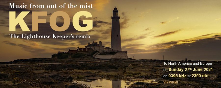
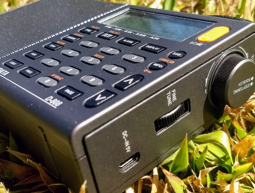
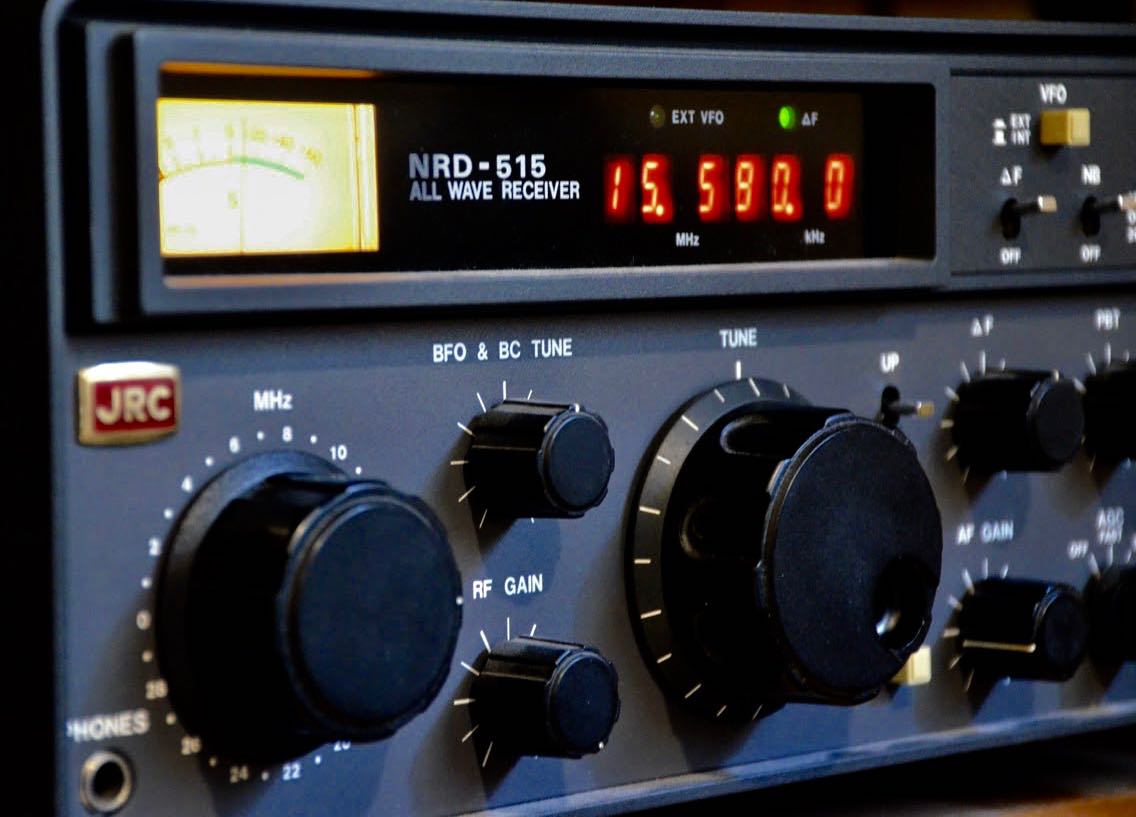
I’ve just learned that KFOG will broadcast a special remix edition via WRMI (9395 kHz) on Sunday June 27, 2021, at 2300 UTC.
“MFJ will begin selling Eton Shortwave Receiver Products effective immediately”
Many thanks to SWLing Post contributors, Eric McFadden and Mike Agner, who share the following announcement from MFJ:
MFJ to sell Eton Shortwave Receivers!
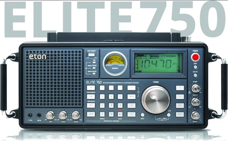
Elite 750
A 360-degree rotating AM antenna enhances the radio’s ability to pull in weak AM signals. You can listen to AM, FM , SW, LW, SSB and aircraft band frequencies, and you can program in up to 100 of your favorites for each band.
Elite Executive
It receives every radio wavelength—AM(MW), FM with RDS, LW, and Shortwave (SW)—at home or abroad. Plus, it also receives VHF aircraft band, Single Sideband (SSB) and includes a PLL tuner.
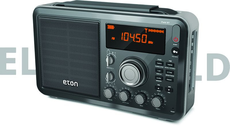
Elite Field
The Etón Elite Field receives most every radio wavelength—AM (MW), FM, and Shortwave (SW)—at home or abroad. It’s easy to set the station spacing and frequency so your stations come in loud and clear wherever you are. And with Bluetooth®, you can stream your own music or favorite podcast.
Eton Traveler AM/FM/Shortwave Radio with World Time and Auto tuning storage, 500 memory stations, automatic or manual tuning. FM with Radio Data System.
Eton Mini AM/FM/Shortwave radio with digital tuner and display which shows frequency, time, and alarm activation, automatic frequency up/down scanning.
Eton Leather Custom Satchel for the Eton Field AM/FM/Shortwave Radio.
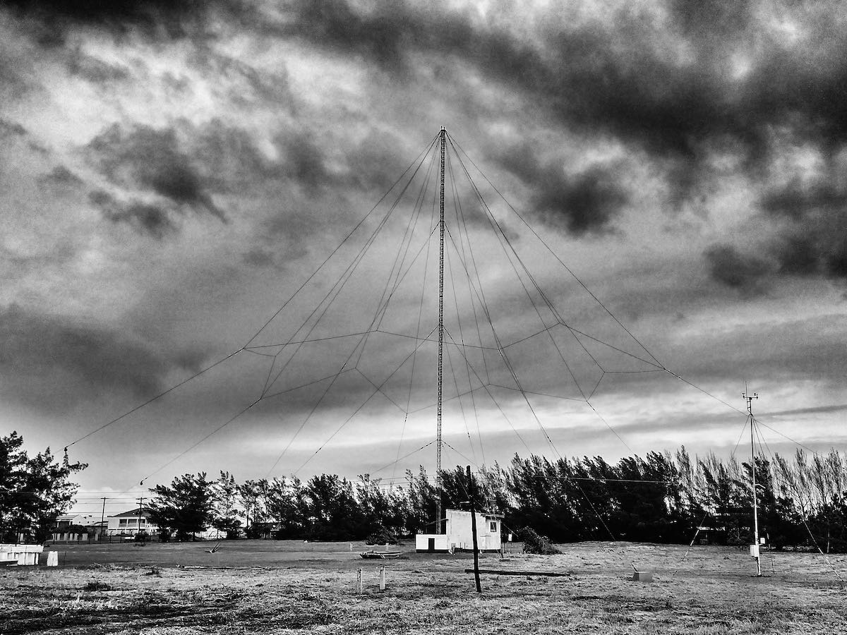
Brazilian Navy’s beacon antenna
Can you ID these HF transmissions?
Many thanks to SWLing Post contributor, Carlos Latuff, who shares the following video of sounds he heard on HF. Carlos adds, “Are we in the Twilight Zone or Lost in Space? They sound like effects from a 60’s/70’s sci-fi movie!”
Those sounds are wild! The stuff of Star Wars.
My only guess is that it’s a form of OTH RADAR? I’m sure an SWLing Post reader will sort this out in short order! Please comment!
Comrade Africa: A historic look at the GDR’s Cold War era shortwave broadcasts to Africa
 Many thanks to SWLing Post contributor, Ulis (K3LU), who shares the following note via his Twitter feed:
“Comrade Africa” – a historic look at the GDR’s (Radio Berlin International) Cold War era shortwave broadcasts to Africa via the BBC World Service:
Click here to listen to the documentary at the BBC World Service.
Radio Waves: New Ham Radio Store, SDR Market worth $14.5 billion by 2025, Retaining 87.7 FM, and Hard-Core-DX now on Slack
Radio Waves: Stories Making Waves in the World of Radio
Because I keep my ear to the waves, as well as receive many tips from others who do the same, I find myself privy to radio-related stories that might interest SWLing Post readers. To that end: Welcome to the SWLing Post’s Radio Waves, a collection of links to interesting stories making waves in the world of radio. Enjoy!
Many thanks to SWLing Post contributors Tracy Wood, Bill Patalon, Dennis Dura, and Mike Agner for the following tips:
Amateur Radio Field Day synchronized with radio store’s Grand Opening (Ramona Sentinel)
Ham radio hobbyists will test their emergency preparedness skills alongside All Day Radios’ Grand Opening celebration in Ramona next weekend.
The Amateur Radio Field Day, a national emergency preparedness activity sponsored by the American Radio Relay League (ARRL), will be held in Ramona from 11 a.m. Saturday, June 26 and continues for 24 hours until 11 a.m. Sunday, June 27.
All Day Radios co-owner Peter Von Hagen will coordinate his Grand Opening in sync with Field Day from Friday through Sunday. The store is at 2855 state Route 67 between Dye Road and Hope Street, and Field Day will be held next door.
Von Hagen said the object of Field Day, held annually the fourth weekend in June, is to communicate on as many stations on amateur bands as possible to test the capabilities of communications equipment. Operators will be using backup sources of power such as solar power and batteries, he said.[…]
Software Defined Radio Market worth $14.5 billion by 2025 (Markets and Markets Newsletter)
The demand for software defined radios, especially in the commercial applications, such as telecommunication, transportation, and commercial aviation, has been affected to a great extent. Due to precautionary measures undertaken by many countries to stop the spread of COVID-19, several public/private development activities have been stopped, resulting in a drop in demand for software defined radios. However, this trend seems to vary from country to country. For instance, the demand for software defined radios in Europe and the Asia Pacific has been affected by the pandemic owing to the stoppage of development activities.
Based on application, the commercial segment of the software defined radio market is projected to witness the substantial growth during the forecast period
In terms of application, the market is segregated into commercial and defense. The rising usage of SDRs in commercial applications including aviation communication, marine communication, transportation, telecommunication is supporting the segment growth. Software defined radios are predominantly used in Air Traffic Control (ATC), transportation, and telecommunication applications. They are easily upgradable and provide high data transmission rate that further enhances its usage for commercial segment.
Cognitive/ Intelligent radio sub segment of the software defined radio market by type is projected to witness the highest CAGR owing to increasing improvements in cognitive radio products.[…]
FCC Report 6/13: Has A STA Based Doorway Been Cracked Open To Retain 87.7 FM Operations? (Radio Insight)
The FCC has sent another reminder to licensees of analog low power television stations regarding the July 13 drop-dead date. If an analog LPTV has not applied for a digital CP by that date its license will be cancelled and those that have Construction Permit’s but will not be ready to broadcast digitally will need to file a waiver request but still will be required to turn off their analog signal on the 13th and cease operation until ready to begin operating with their digital facilities.
This will of course affect the thirty something LPTV’s on analog channel 6 operating as radio stations on 87.75 MHz. While some of these signals will be moving to other channels, many will be remaining on channel 6 and have spent the past few years seeking loopholes to continue to broadcast an analog audio signal past the digital conversion deadline. Venture Technologies Group, which owns five affected stations, threw the door wide open this week with the grant of a six month STA for its KBKF-LD San Jose CA. KBKF-LD, which is leased to Educational Media Foundation to air its “Air 1” network, will be permitted to continue to offer an analog audio signal on 87.75 FM in its ATSC 3.0 digital video signal.[…]
Introducing: Hard-Core-DX Slack Chat (Hard-Core-DX)
From: Risto Kotalampi
Hi all,
Hard-Core-DX has been a pioneer in connecting shortwave listeners for nearly 30 years now. In its core it has been emailing lists and web sites and some other experiments which have either spun to become popular on their own (e.g. various ham related spotting sites or Online Log which is very popular in Finland) or not. Today we wanted to try to branch out into chat using Slack.
This is not the only chat there is… IRC, Facebook, Whatsapp etc have small circles for shortwave listeners but they have all been closed systems and not enabling an environment that can be used across devices and have conversations about any topics we choose. In the corporate world Slack has revolutionized communications amongst colleagues and partners in different companies. Much of work in U.S.A. small companies happens nowadays in Slack and not so much in emails.
Hard-Core-DX has signed up and created it’s very own Slack service.
If you want to join the HCDX Slack, please click this link and create your own HCDX Slack account:
https://join.slack.com/t/hard-core-dx/shared_invite/zt-rn83gamf-_UCfo9LYUVmoIBhb0~3cSg
Some basic rules of the Slack service:
- When you join it, you will see some channels that have been created already. You can join them or if you can’t find the topic you’d like to chat about, please create your own.
- HCDX will not be in the business of moderating what people are creating or discussing. If you create a channel, you will choose the policies of the discussion.
- This can naturally invite some abuse. We will deal with it with Slack’s policies as time comes.
- You are welcome to invite your DX friends to the HCDX Slack and grow the community. Invite happens from menu in upper left corner and link “Invite people to Hard-Core-DX”
- Let’s keep subjects within shortwave radio, broadcast, utility, pirate DXing & ham radio if possible to keep the service relevant to us
- This is an experiment… if it doesn’t gain popularity or becomes a burden, we will shut it down. But for now, if you want to experiment and see if this is where you want to chat with your DX friends, join the fun.
Do you enjoy the SWLing Post?
Please consider supporting us via Patreon or our Coffee Fund!
Your support makes articles like this one possible. Thank you!
FTIOM & UBMP, June 27-July 3
From the Isle of Music, June 27-July 3:
Part 2 of 2 parts: This week, our guest is Rodney Barreto, winner of the Making Of category in this year’s Cubadisco and a nominee in Jazz for Drummer Negrito. He also performed in several other nominees and winners of Cubadisco. Our conversation will be in English.
The broadcasts take place:
1. For Eastern Europe but audible well beyond the target area in most of the Eastern Hemisphere (including parts of East Asia and Oceania) with 100Kw, Sunday 1500-1600 UTC on SpaceLine, 9400 KHz, from Sofia, Bulgaria (1800-1900 MSK)
2. For the Americas and parts of Europe, Tuesday 0000-0100 UTC on WBCQ, 7490 kHz from Monticello, ME, USA (Monday 8-9PM EDT in the US).
3 & 4. For Europe and sometimes beyond, Tuesday 1900-2000 UTC and Saturday 1200-1300 UTC on Channel 292, 6070 kHz from Rohrbach, Germany.
Our Facebook page is https://www.facebook.com/fromtheisleofmusic/
Our V-Kontakte page is https://vk.com/fromtheisleofmusic
Our Patreon page is https://www.patreon.com/tilford
Uncle Bill’s Melting Pot, June 27-July 3:
In episode 223, we present new and recent releases from various countries.
The transmissions take place:
1.Sunday 2200-2300 (6:00PM -7:00PM EDT) on WBCQ The Planet 7490 kHz from the US to the Americas and parts of Europe
2. Tuesday 2000-2100 UTC on Channel 292, 6070 kHz from Rohrbach, Germany for Europe.
3. Saturday 0800-0900 UTC on Channel 292, 9670 kHz from Rohrbach, Germany for Europe with a directional booster aimed eastward.
Our Facebook page is https://www.facebook.com/UncleBillsMeltingPot/
Our V-Kontakte page is https://vk.com/fromtheisleofmusic
Our Patreon page is https://www.patreon.com/tilford

