Tag Archives: Mag Loop Antennas

Shortwave antenna options for apartments, flats and condos

A balcony is your friend, if you have one. Otherwise, we need to use other antenna tactics!

Many thanks to SWLing Post contributor, Tim, who writes:

I am a regular subscriber here, but until now have not formally commented. I’ve been an avid SWL since 1977.

I am intrigued by your in-depth article on understanding and setting up SDR’s. But, what about an antenna? How well will these radios work for someone who is an apartment dweller?

I live here in South Florida and am unable to erect anything outdoors. I do get pretty good reception on my Grundig Satellit 800 and Tecsun PL-880. For these, I use either an indoor slinky antenna I bought on E-Bay; or an active indoor tunable loop antenna. This is one of the models past reviewed by you. It is Australian made, and covers 6-18 MHz. Please comment if you can on antenna usage.

Thank You very much!

First of all, I’m glad you enjoy the SWLing Post, Tim!

Great question: no doubt you understand that the antenna is the most important part of your radio equation!

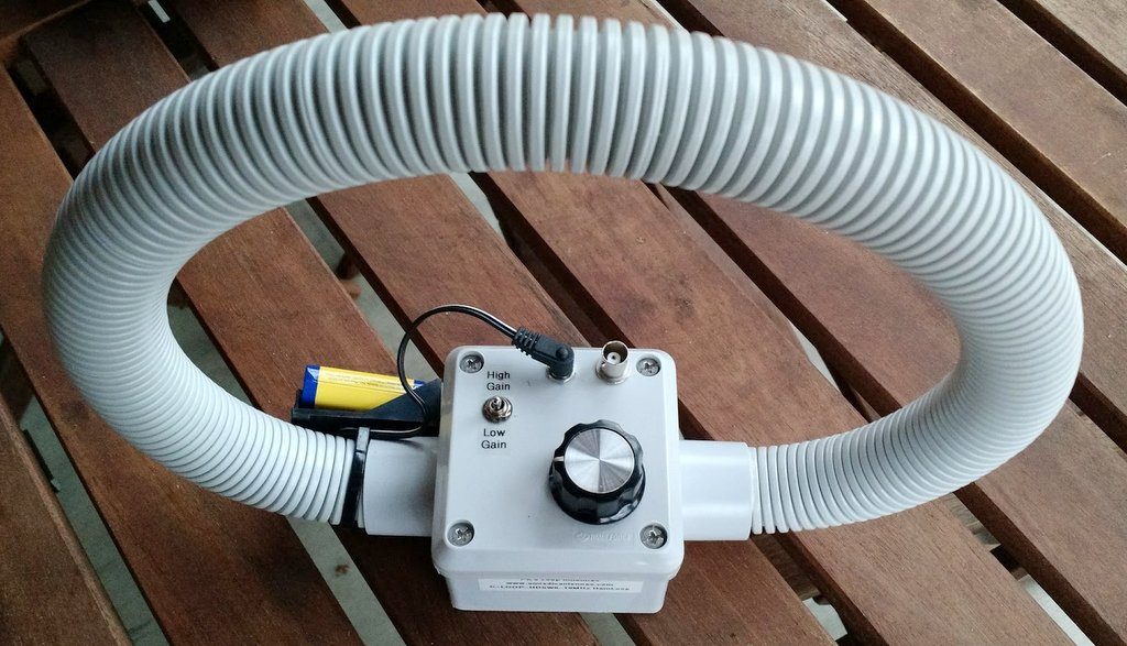
It sounds like you’re currently using a slinky antenna and a portable PK Loop HF antenna.

The PK Loop

You’re on the right track with a PK Loop if you live in an apartment and have no way of putting an antenna outdoors. Being a small magnetic loop antenna, the PK Loop should help mitigate a bit of the noise in your apartment building.

What I love about the PK Loop is it’s small enough that you can re-position and rotate it to tweak noise rejection and find the quietest spot in your listening room. When I travel by car and even by air, the PK Loop is a welcome companion.

Before we talk about investing in a better indoor antenna, let’s make sure we cover a more affordable option first…

External wire antennas

If you have operable windows in your apartment, even fishing a thin-gauged wire out of your window–allowing it to simply hang along the outside of the building–could improve your reception significantly. Of course, if there’s a source of noise outside of your apartment it might only make things worse, but this is at least an inexpensive experiment and the results might impress you.

I actually tested this theory once and published the following results in a previous post about the PK Loop:

I had a fantastic opportunity to evaluate how well the PK Loop would perform in a typical hotel room. My buddies Eric (WD8RIF), Miles (KD8KNC) and I stayed overnight in a hotel on Wright-Patterson Air Force Base during our mini National Parks On The Air DXpedition.

The hotel room was indeed dense with RFI.

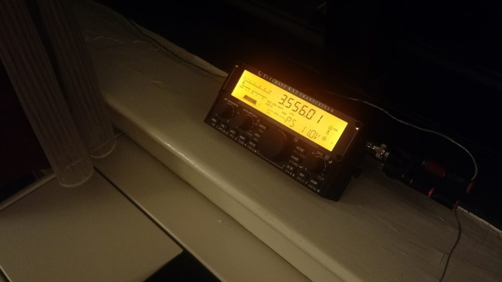
We hooked my Electraft KX2 to both the PK Loop and to a simple random wire antenna.

Without a doubt, the PK Loop was much better at mitigating radio noise than the wire antenna we hung on the inside of the hotel window.

Unlike most modern hotels, however, this one actually had operable windows, so we tossed the random wire out the window and made another comparison. In this case, the external wire antenna consistently outperformed the PK Loop, no doubt because it had the advantage of being outside the radio noise cloud within the hotel’s walls. It goes to show that outdoor antennas–even if simply hanging from a room window–will almost always outperform comparable indoor antennas.

So, if you have a way to dangle a wire out one of your window, give this a try.

How long should the wire be? I suppose it depends on how much vertical space you have below your window. For starters, I’d try to suspend at least eight feet of wire outside. If I had the vertical space, I’d try as much as 31 feet.

Important: First you must check to make sure your wire couldn’t possibly touch electrical lines. Never lower a wire outdoors if the wind could blow it into an electric service entry point, power line or any other type of line or cable. You should do a thorough inspection of the site first.

With that said, keep in mind: Stealth is key!

Photo by jay blacks on Unsplash

Can you spot the wire antenna in this photo? Of course not.

Use a thin wire with a black or dark jacket/insulation. Only lower it when using it–don’t leave it out all day long. Check to make sure your antenna isn’t going to interfere with your neighbors below (like landing in their outdoor grill or flower pots!). One strong complaint from neighbors could shut down your operation permanently.

Now back to loops…

If you don’t have operable windows or a way to deploy a wire antenna outside–or you’ve tried a wire antenna and results were unsatisfactory–then you will be forced to stick with indoor antennas which almost always leads you down the path of larger amplified wideband magnetic loop antennas.

This is a topic I covered extensively earlier this year.

Please read the post: Indoor shortwave antenna options to pair with a new SDR.

Indoor shortwave antenna options to pair with a new SDR

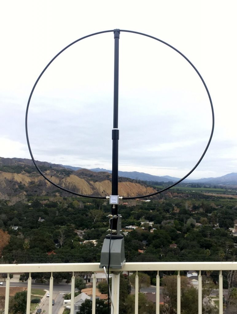
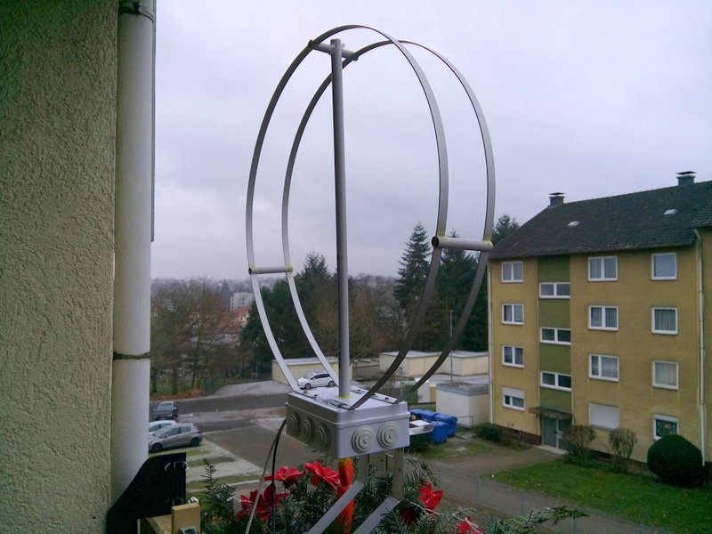
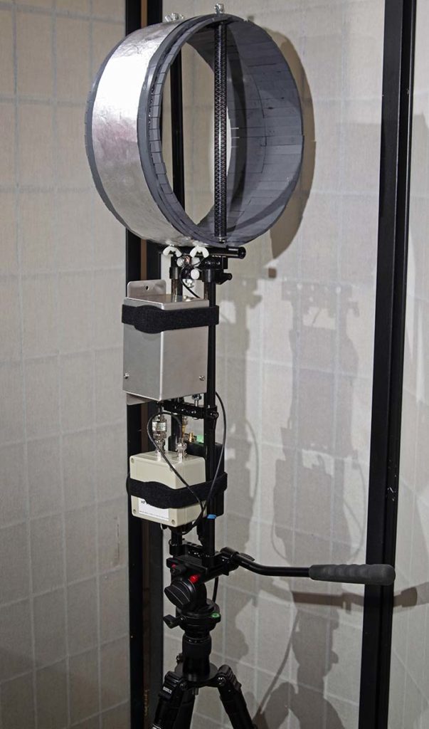
Keep in mind that if you’re fortunate enough to have a balcony, this is where you should mount your loop antenna. Check out this post by SWLing Post contributor, Klaus Boecker.

Klaus Boecker’s homebrew magnetic loop antenna.

Note that there are a number of sub $100 indoor amplified antennas on the market, but I would avoid using them–click here to read my thoughts about these.

In addition, read through this post which includes practical low-to-no-cost tips and best practices for shortwave listening at home and on the go.

Frugal SWLing: Investing little, but getting a lot out of your radio

I’m plotting to write a more in-depth article about antennas in the coming months, but it will focus on external antennas and methods of mounting them. When you have no means of mounting an antenna outdoors, in my opinion, your best options are the ones mentioned above.

Post readers: Have I overlooked an indoor antenna option? Please comment if you have experience with indoor antennas!

Do you enjoy the SWLing Post?

Please consider supporting us via Patreon or our Coffee Fund!

Your support makes articles like this one possible. Thank you!

Spread the radio love

Bill tweaks his AM loop antenna for optimal mediumwave performance

Many thanks to SWLing Post contributor, Bill Hemphill (WD9EQD), who writes with the following update to his previous post:

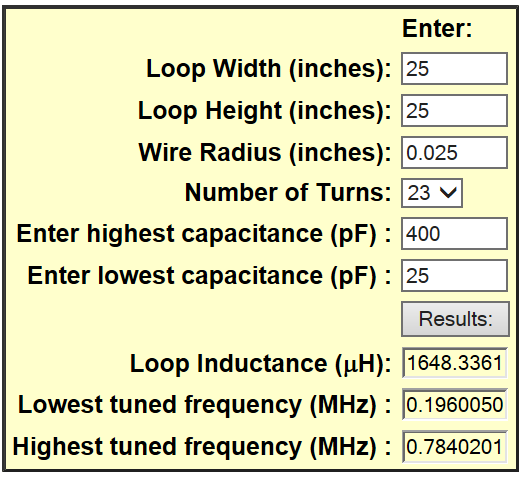
As you may remember, back in May, I picked up a beautiful home-made loop antenna. It was 25 inches on a side with 23 turns of wire. My initial testing showed that it would tune from 280 kHz to 880 kHz. While I was familiar with loop antennas, I had never tried using one.

My initial tests were disappointing. So I spent some time on the internet reviewing AM loop antenna designs. I came across a reference to an AM Loop Antenna Calculator by Bruce Carter:

http://www.earmark.net/gesr/loop/umr_emc_calc.htm

I first measured the tuning capacitor and found that it tuned from 25 to 400 pF. Entering the data into the calculator:

This matches closely to what I was experiencing.

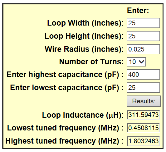
I then proceeded to calculate various Number of Turns to see the effect on tuning range. My goal was to tune the entire AM broadcast band.

I settled on ten turns which gives the following from the calculator:

Perfect. I removed 13 turns (which left ten turns) and then added a two turn secondary loop which would be connected to the radio. The results were fantastic.

I have created three short videos showing the difference between using the Tecsun S-8800 without the loop on a weak station and then using it with the loop.

[Note: If you’re viewing this post via our email newsletter you might need to view this post via a web browser to see the following embedded videos.]

Without the loop

With Loop

As you can hear, a very noticeable difference.

[After making these videos] I tested the of reception of 1510 kHz on the Panasonic RF-2200:

The results are amazing.

I have logged three stations on one frequency. Just peak the one station, then tune the loop and peak the second, then turn the loop some more and peak a third station.

I’m having a lot of fun with the loop. When it gets a little cooler, I plan to take it to the park where there is zero noise and really put it through its paces.

Excellent job, Bill! You’ve proven that doing a little research and making small adjustments to an antenna design can yield impressive results! Thank you for sharing!

Spread the radio love

Guest Post: SM0VPO’s 3D Printed 10KV Tuning Capacitor

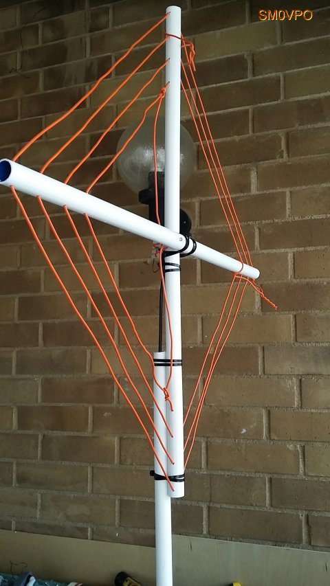
The completed antenna.

Many thanks to SWLing Post contributor,Harry Lythall (SM0VPO), who shares the following update to his excellent homebrew 20 meter magnetic loop antenna post:


3D Printed 10KV Tuning Capacitor

by Harry Lythall (SM0VPO)

Introduction

You may have seen my 20m (14MHz) loop, or frame, antenna, and the ease of construction with just a bit of wire and a bit of plastic tube. The tuning arrangement is a little primitive, using just a “gimmick capacitor”, comprising two bits of wire twisted together.

The original “Gimmick” capacitor that burns.

This arrangement works very well for QRP, where the average RF power is about 5 Watts or less. If you exceed this power level, then the twisted-wire capacitor tends to warm up and the tuning drifts a little. But if you use more than about 10 Watts of continuous RF power, then things start to burn. Cheap insulated wire also smokes. This is because the impedance at the ends of the coil is so high that you can get many 100s of volts and the insulation, normally intended for house wiring, breaks down.

In this page I will show you how to build a super-cheap tuning capacitor that will tolerate up to 10,000 Volts of RF and allow you to use up to about 100 Watts of RF into my 14MHz (20m) antenna. The capacitor is also tunable so that you can adjust it by hand (when the RF is removed, of course :-). The tuning range is about 8pf to well over 30pf when really compressed. The normal range for the antenna is about 12pf to 15pf.

Construction

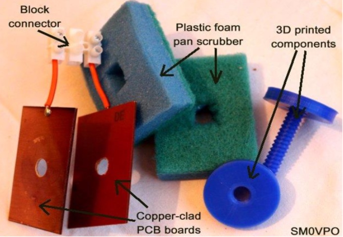
My prototype does not look very pretty, and it is not supported on anything other than the connection wires from the antenna. Very few components are used:

  • two plastic foam pan scrubbers or one thick plastic bath sponge
  • two pieces of metal 4cm x 6cm. Copper-clad board works fine
  • one plastic nut and bolt – see text
  • one heavy-duty 3-pole block connector with centre-pole removed

Components for the 10KV tuning capacitor

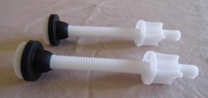
The plastic nut and bolt need to be about 6cm long and totally non-conductive. If you want to make my bolt, then do NOT use black plastic because some black plastics use carbon as a colouring agent. You can use a nylon bolt, as used to secure IKEA toilet seats, but you will also need a washer to spread the stress, otherwise the copper-clad board tends to bend under the stress with time. I chose copper-clad board because it is easy to solder – no need for drilling or connection bolts. I made my plastic compression tuning bolt using my 3D printer. I have included the project files for you to download.

Ikea toilet-seat bolt

Note that the connector for the wires needs to be well spaced between the metal inserts, in order to tolerate up to 10KV, so I used a 3-pole connector and took out the centre pole. At 100-Watts continuous there is a very slight warming after a few minutes, but no sign of smoke, sparks or corona. 🙂

The connector with the centre-pole removed.

I tried a few different types of plastic dielectric and all worked well, providing they are 100% dry. The best ones those I stole from the kitchen cupboard (when Maj-Lis was not watching). I think it costs about $1.50 for a packet of 10 pieces. Perhaps I should have used a nicer colour? A pretty pink? Heart-shaped? No! maybe that would be going a bit too to far ;-). Here is my finished capacitor using my 3D printed tuning screw.

The assembled 10KV capacitor.

3D Files

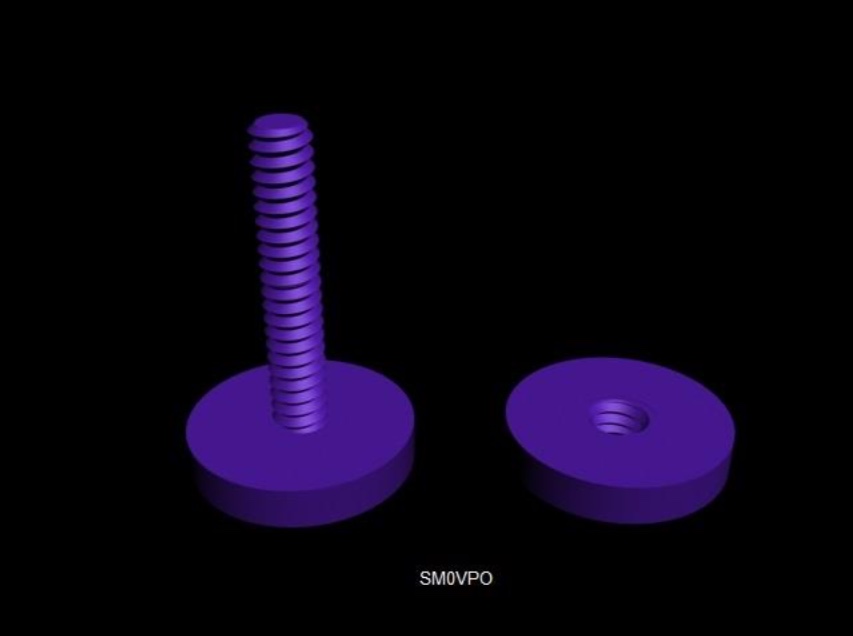
Once more, this project is ridiculously easy to make with a 3D printer. The hardest part was to get the pitch of the threads right, then clone/connect the pieces to get a longer thread. They were printed with the bolt vertical, so the slope under each thread is a steeper angle than the upper slope. This makes the printout a lot easier to print. If the angle is too steep, then it may extrude PLA into mid-air. My nut and bolt heads are about 3cm Diameter, and the 10mm thread for the nut was cut using boolean subtraction. I then enlarged the nut by about 3% so it still fits but there is a little slack so that it does not bind. I may have overdone it a little, but not much.

Project rendered in 3D Studio Max

Here are the files:
3D studio MAX file – 3d-cap-01.max
ASCII STL file – 3d-cap-01.stl
ASCII OBJ file – 3d-cap-01.obj
the GCODE file for my Wanhao (Prusa) Duplicator i3 – 3d-cap-01.gcode

Just right-click on the file and select “save as”. Some web browsers try to open ASCII files instead of saving them. I usually export STL files, but on this occasion, I tried comparing OBJ files since CURA slicer will accept both. Although I use a WANHAO replica of the PRUSA Duplicator i3 printer, the GCODE files are rather generic and will probably work on most printers.

My printer settings in this GCODE are:

  • Nozzle temperature = 200°C
  • Bed temperature = 60°C
  • Support structure = brim
  • Layer height = 0.1mm
  • Print speed = 60mm/s
  • Fill density = 40%
  • Shell thickness = 1.2mm

The printer temperature is 200°C, which is 5°C hotter than recommended for PLA filament. I find that I get a better print at 200°C as it sticks to the bed a lot easier. When printing this screw thread, it may be advisable to start at 200°C and then turn down the nozzle temperature to 195°C after a few layers have been printed.


I hope that you find this project interesting. It is a bit small, but it gets me active on 14MHz from my car with this portable antenna. I have a new car and I don’t want to start throwing long aluminium tubes in it that scratch the interior to bits.

Don’t forget to visit my messageboard if you have any questions about this or any other project. I always look forward to receiving feedback, positive or negative ?

Very best regards from Harry Lythall
SM0VPO (QRA = JO89WO), Märsta, Sweden.
EA/SM0VPO (QRA = IM86BS), Nerja, Spain.


Thank you so much for sharing this, Harry! I love both the frugality and ingenuity in this unique capacitor design!

Post Readers: be sure to check out Harry’s website which is loaded with radio projects of all stripes. You’ll easily spend a few hours digging through his tutorials and downloads. Harry also maintains an alternate mirror server located here.

Spread the radio love

How to build SM0VPO’s 20 meter magnetic loop antenna

The completed 20 meter loop antenna.

A few days ago, SWLing Post contributor, Robert Gulley (AK3Q), pointed me to an excellent website by Harry Lythall (SM0VPO) which is chock-full of various homebrew radio projects. In particular, we both were impressed with Harry’s 20 Meter Loop Antenna–it’s such a simple project and requires no special order components. In fact, all of the components (save, perhaps, the antenna connector) can be purchased at a DIY store.

I reached out to Harry and he has kindly allowed me to republish this project as a guest post:


20m Loop Antenna

by Harry Lythall – SM0VPO

Introduction

I recently saw that my 80m (3.5MHz) loop (or frame) antenna has been really popular, and that there are loads of other radio amateurs who have taken my design and “ran with it” to produce variations that all have some great improvement. There have been many in-depth tests and simulations, all with exceedingly good results and reports. This is exactly what I am aiming for with my homepages – free information for all and my designs being improved upon. That way we all win 🙂

One small point all variations have in common is the need for an expensive tuning capacitor and a very restricted RF power level. Of course, you can throw money at the problem, but for me this hurts. I got to thinking that there must be a way of adjusting the design a little and finding another technique to tune the antenna, and to make the best use of the little radio transceiver I have in Sweden, given the limited space.

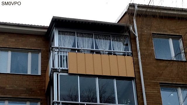
My limited space apartment.

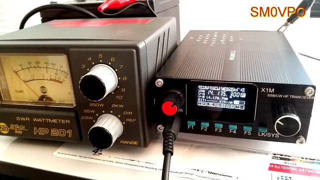
As you can see there is not much opportunity for grand antennas. And to add to this, the equipment I have in Sweden is also limited to a single 5-Watt unit.

My limited equipment – only 5-Watts.

The Design Thoughts

Today I have no area of land to use for antennas. I have a glassed-in balcony on the 4th floor of an apartment block. I really like the 20m (14MHz) band so I will concentrate on that. I am not really interested in the CW end of the band, except perhaps 14.070MHz for the digimodes. So my requirements are:

  • As efficient as possible (useable)
  • Small size, also portable so I can use it for field use
  • No expensive components, everything available locally
  • No TVI, QRM or interference to stereos or computer sound
  • Total price less than $2

The antenna I have created is based on my original 3.5MHz loop (or frame) antenna. This time I built it out of scrap components. I cadged (tiggade) some plastic conduit tubes from an electrical contractor at work. The same guy also gave me the remnants of a roll of 2.5mm C.S.A. multi-strand mains cable. That was all I needed.In my junkbox I found no tuning capacitors, but WAIT!! Why do I need to tune the antenna? Once it is tuned I should not need to tune it again, just set the centre-frequency to 14.175MHz. If I can get the Q-factor to around 100 then my useable 3dB bandwidth should be more than 150kHz. That will give me 14.10MHz to 14.25MHz.

Ok, I need a 1-off, preset tuning capacitor. Why not use a Gimmik Capacitor? Just twist two bits of wire together and cut it short to get the resonant frequency I want. So I need to get the coil wound so that there is sufficient cable length and self capacitance to give a resonance of about 14.5MHz without any extra capacitance what-so-ever. That means I need just a few pf. That sounds like a good plan.

Construction

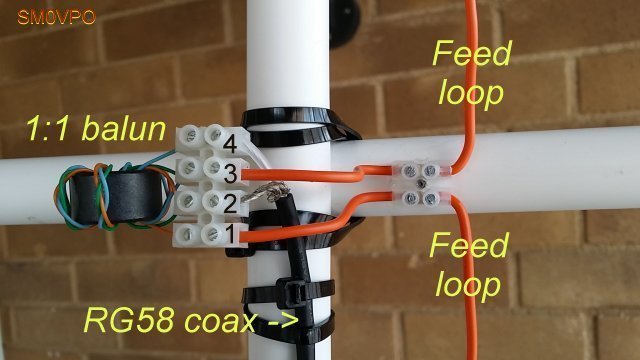
The 15mm Diameter plastic tube I “aquired” were 80cm long. After much trial and error I found that exactly 3 turns, with 2.5cm spacing, gives about 14.9MHz self resonance. The wire support holes are exactly 4cm spaced, beginning 1cm from the end of each tube. The two tubes are fixed into a and X using zip-straps (tie-wraps, buntband). The feed loop is 1/2 turn.

Note the size and position of the feed loop. Also the Gimmik capacitor.

One problem I had with the original loop antenna was that of RF coming back down the cable braid. Using on old FT-101ZD it was possible to feel the RF on the microphone with your lips. The cure for this is to use a balanced feed and at least 5m of RF cable.

I robbed the ferrite ring for the balun from an old ATX computer PSU and made a triflar wound torroidal transformer. That is to say, twist together three lengths of 1mm x 7-strand insulated hookup wire together. Use this to make a 7-turn coil and connect the three coils in series, with four connections. Feed connections (numbered in the picture below) 1 and 3 are connected to to the antenna feed loop. Connect the coaxial cable braid to connection 2, and the coax centre to connection 4. My balun is self-supported on the connection leads.

The 1:1 Balun I used.

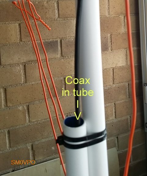
The coaxial feed cable was found to affect the resonance slightly, so I fed that through an extra bit of tube to make it stay in one place. It works fine.

Feeder cable secured in the support tube.

Testing

Testing is very easy. I used my GDO-2 to check the middle-turn of the loop for a dip. Twist the two tails together to form the Gimmik capacitor and adjust the length of the twist until the centre-frequency is 14.175MHz. With the GDO you can get it within about 100kHz to 200kHz, but then you can check the VSWR using your HF radio. You can also sweep the band for maximum noise and get a very close approximation.

The Gimmick capacitor.

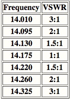
The centre frequency of my 20m Loop antenna is 14.175MHz, and the VSWR is better than 1.05:1 (I can hardly see any movement on my meter). The Q-factor is somewhere approaching 100. The useable bandwidth is just a little narrower than I would have wished, but the antenna certainly works well and meets all the other criteria. But the slightly less useable bandwidth criterion is at the expense of better performance, and it still allows me to use 14.070MHz, although it is a little quieter down there.

The completed antenna.

Conclusion

No-matter how you play with the figures, the best indoor antenna cannot replace a full-size dipole antenna. But the indoor antenna can give some extra features, such as just reaching out your arm and trimming a little, which you cannot do with a long-wire antenna up a tree out in the garden, especially when it is raining.

This antenna gets me on the air on 14MHz, and it has a useable frequency range. The VSWR is almost perfect at the centre-frequency, and this time I don’t burn my lips on the microphone (not that I am likely to do so with just 5-Watts of power). The design uses no expensive components, in fact the only item I bought was the block-connector for the balun. That cost me US$1.50 for a pair of 12-contact screw-terminals. The construction is ridiculously simple and easy to build.

On the air I can hear traffic on 14.070 digimodes, and from 14.130 to 14.220MHz I have a near-perfect VSWR aqnd good clear reception of SSB. I can also rotate the antenna to cut out rubbish, and most of all, using the Gimmik capacitor I don’t need to re-tune it: it seems temperatore-stable. The weight is less than 500g and when I poke it out of the balcony window the reception improves, the VSWR does not change, and I can make myself heard among the big boys.

I hope that you have some fun building and using this antenna. If you have any ideas for further improving it then please use my forum.

Don’t forget to visit my messageboard if you have any questions about this or any other project. I always look forward to receiving feedback, positive or negative.

Very best regards from Harry Lythall
SM0VPO (QRA = JO89WO), Märsta, Sweden.
EA/SM0VPO (QRA = IM86BS), Nerja, Spain.


Many thanks, Harry, for sharing this excellent project on the SWLing Post!

Post Readers: be sure to check out Harry’s website which is loaded with radio projects of all stripes. You’ll easily spend a few hours digging through his tutorials and downloads. Harry also maintains an alternate mirror server located here.

Side note: I’m impressed with the fact that the main SM0VPO website is actually hosted on a bedside Raspberry Pi computer (running the Linux-based Lighttp server).  Very cool!

Check out other homebrew mag loop antenna projects on the SWLing Post by clicking here.

Spread the radio love

Bill scores a homebrew LW/MW magnetic loop antenna

Many thanks to SWLing Post contributor, Bill Hemphill (WD9EQD) who shares the following:

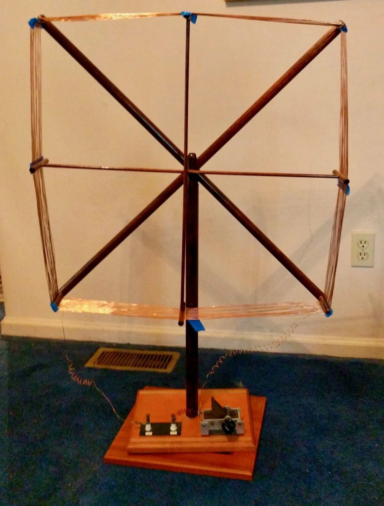
I went to the Warminster Amateur Radio Club (WARC) hamfest [yesterday] in Bucks County, PA. For some time, I have been thinking about making a loop antenna for AM DXing. It was my lucky day. When I walked to the inside tables, on the very first table was this homemade loop antenna gentleman was selling from an estate.

I snatched it up for $40.

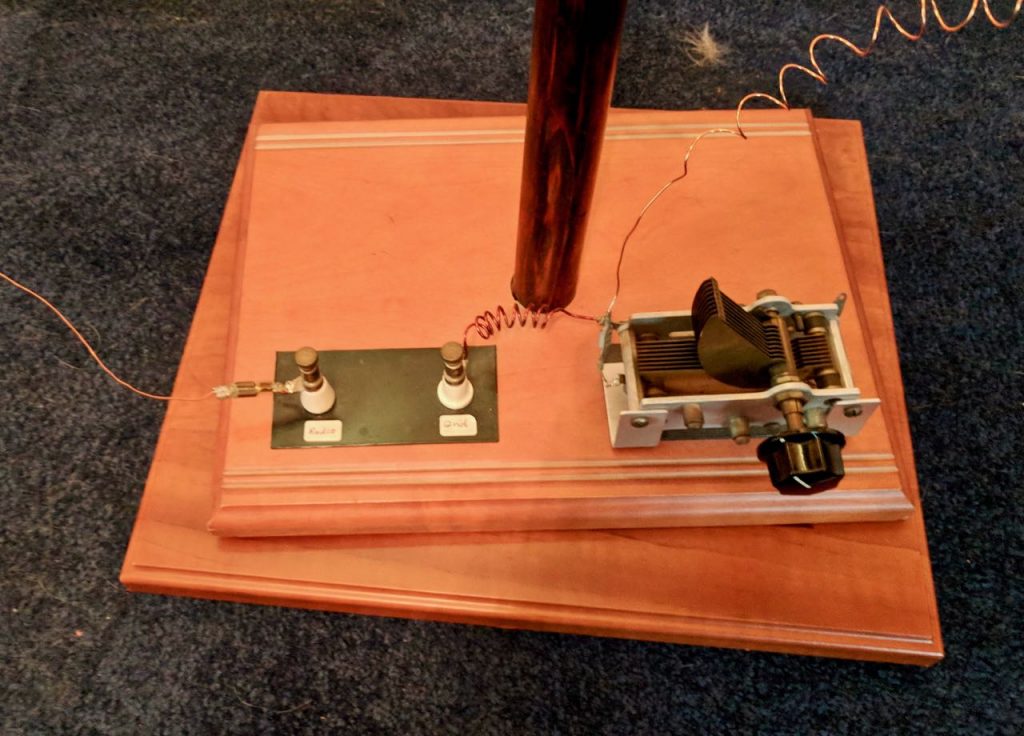
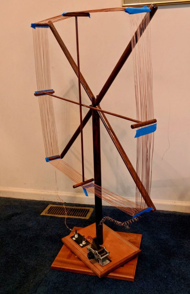
Attached are some photos of it. It’s 25” by 25”, with a swivel base. There are 23 turns of wire and I have no idea what size the capacitor is. I did some preliminary tests and it tunes from 280 kHz to 880 kHz. So it’s the covers the high half of the long wave band and the low half of the AM band.

It’s very well made and I fugue I can modify it to cover the entire AM band.

[…]I hooked the SDRplay RSP2 to it and was getting good signals of major stations all the way to 15 mHz.

That’s with it sitting on my dining room table. Of course the capacitor wouldn’t peak the signals.

So it was a great day at the hamfest!

Indeed that was a great find, Bill!  Someone spent a decent amount of time building that furniture-grade loop support. Indeed, it’s very reminiscent of 1920s-30s mediumwave loops!

What I love about your loop (and that of Thomas Cholakov) is that one can see how simple these antennas actually are to build. The only complicated bit is the support, but even that’s simple if you use the shield of a heavy coax or flexible copper tubing.

Thanks for sharing and enjoy logging DX with your new-to-you loop!

Spread the radio love

Video: Homebrew AM Loop Antenna Project by Thomas Cholakov (N1SPY)

Many thanks to SWLing Post contributor, Thomas Cholakov (N1SPY), who shares his latest video explaining the operation of a simple homebrew AM loop antenna:

Click here to view on YouTube.

Brilliant video, Thomas! I love the fact you included a demonstration with your SDRplay RSP1A as well. Via the spectrum display, it’s easy to see the the loop’s bandwidth and also the gain it provides when tuned to a station.

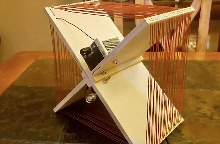
I love your AM loop antenna as well–such a simple design and ideal for demonstrating the mechanics of a passive loop antenna since all of the components are visible. I’m willing to bet you built this antenna for less than $10. Smart design as it’s both portable and effective! Keep up the excellent work, Thomas! We look forward to all of your future videos.

Spread the radio love

Backpack Shack 2.0: an update from the field

Finished Backpack Loop 2.0 and accessories assembled together

Many thanks to SWLing Post contributor, TomL, who shares the following update about his homebrew Backpack Shack 2.0 portable loop antenna:


Quick Field update

by TomL

This is just a quick Field Update for my Backpack Shack 2.0 antenna. It is not the most powerful antenna but in the right location it can be useful, especially with using an SDR. It was used during February in two Forest Preserve (County Park) locations outdoors and once from my usual Grocery Store parking lot!

Field Recordings

Please excuse some of the computer generated noises (caused by a slow CPU) as well as some audio connector problems on a couple of recordings.

Each Time is in UTC and Frequency in kHz. Where can you hear unique programming like these samples except Shortwave Radio??? Enjoy!

VOA, @03:00 on 6080 kHz in English from Sao Tome towards Africa (backside of their antenna, opposite of my location)

China Radio Int’l, @23:00 on 9415 kHz in Vietnamese from Beijing (not sure if this traveled around Antarctica to get to me or a backside of their antenna over the North Pole?)

WHR, @15:59 on 9965 kHz in Korean from T8WH Palau

Mighty KBC, @01:48 on 6150 kHz in English from Nauen Germany (announcer sound effects included!)

Voice of Greece, @20:34 on 9420 kHz in Greek from Avlis (unique stylized Greek music, INTERESTING artistic expression)

Vatican Radio, @20:27 on 9660 kHz in English from Vatican City to Africa

WINB, @21:30 on 9610 kHz in English from Red Lion, PA USA (a FUN song about promoting Radio listening!)

And my favorite Government-run authentic folk music station of Mexico, tiny 1KW XEPPM @04:17 on 6185 kHz with clear station ID

I will be working on a larger version of this antenna to transport in my car as well as a small VHF loop antenna for the outside deck for Air/Police/Weather scanning.

Hope to report sometime this Spring.


Thank you so much for the update, Tom! It looks to me like you’re having an amazing time with you homebrew loop in the field! 

As always, keep us in the loop! (Yeah…bad pun, I know!)

Spread the radio love