Tag Archives: Magnetic Loop Antennas

Giuseppe’s Crossed Loop and the “VariabilOne”

Many thanks to SWLing Post contributor, Giuseppe Morlè (IZ0GZW), who shares the following:

Dear Thomas and all friends of SWLing Post,

I’m Giuseppe Morlè iz0gzw from central Italy on the Tyrrhenian Sea, Formia.

A few days ago at a fair for radio amateurs in Latina, I bought an excellent very large variable capacitor–those of ancient military radios–and I found a splendid antique knob with a fantastic gear ratio.

I called this VariabilOne and it consists of two sections of 250pf each. It’s very portable and can be applied to any loop with crocodile clips.

I built another cross loop made up of 2 turns the internal loop, 35 cm. and only one turn for the external loop, 40 cm.

I can tune frequencies from 3.500 to 20.0 MHz. The crossed loop is strongly directive given the two loops that work together being joined on their ends.

I have made some demonstration videos and it is a pleasure for me to share them for our entire community (see below).

Thanks to you and I wish you all the best for you and your family.
Greetings to all.
73. Giuseppe iz0gzw.

Click here to view on YouTube.

Click here to view on YouTube.

Click here to view on YouTube.

Click here to view on YouTube.

Giuseppe, thank you once again for sharing your brilliant homemade antenna projects with us. I absolutely love that monster variable cap and tuning whee! What a thing of beauty–and obviously your loop is very effective.

Thank you as always, Giuseppe!

Readers: click here to check out Giuseppe’s other antenna projects.

Spread the radio love

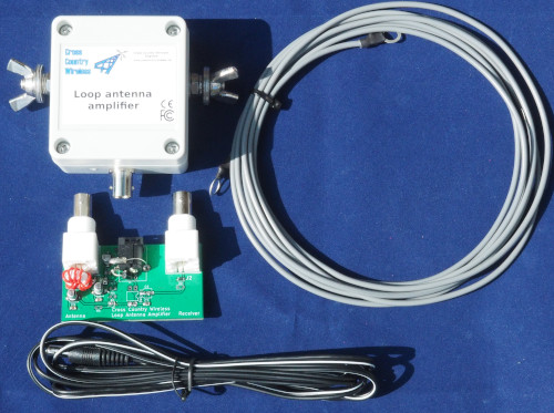
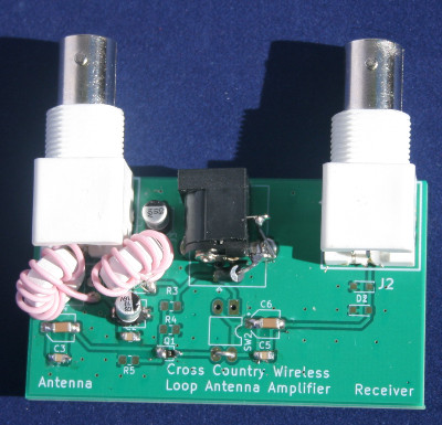
Joshuah says: “The Cross Country Wireless LAA++ amplifier rocks!”

Image Source: Cross Country Wireless

Many thanks to SWLing Post contributor, Joshuah, who writes:

Dear Thomas,

I recently dedicated some funding to rebuilding my shortwave listening station.

I had paid attention to new amplifiers  and became aware of some review data by an engineer at SDRPlay comparing amplifier performance that suggests the Cross Country Wireless amplifier, at a cost of only 80 dollars, had become a competitive design offering performance comparable to amplifiers costing 10 times that much.

I was hooked by the specific demonstrations showing that the LAA++ offered IMD characteristics more similar to a Wellbrook, with gain more similar to other high amplification designs. I had to have one.

I set up my station with the following components:

    • A used Icron Ranger 2304 USB over ethernet extender off eBay
    • A used Airspy Discovery off eBay
    • A Cross Country Wireless receiver protector(or similar ferrite + gas discharge diode isolator)
    • A custom ordered LAA++ amplifier from Cross Country Wireless built for 75 ohm with F connectors and a low pass filter at 14MHz
    • A power inserter from an W6LVP that wasn’t cutting the mustard
    • A pair of classic, solid transforming power adapter bricks
    • An unshielded ethernet cable
    • Some Fair-Rite ferrite snap ons with multiple turns

I obtained a weatherproof enclosure and some pex tubing and specialty cable glands and built an antenna housing. Inside the enclosure I mounted the amplifier, adding a large gauge copper wire for the antenna element, and used an affordable tri-shield RG11 with specialty connectors as the feedline for the antenna.

The antenna measures approximately a 2 meter diameter, and is mounted about 5 feet off the ground at the base of the antenna. It is located outside of a remote shed at the edge of my property, and the ethernet (alternatively, wireless repeating parabolic dish with router) mirrors the USB data back to the PC in my basement which serves as the shortwave receiving server host.

I have been overwhelmed both with the amount of new noise and new signal that this antenna picks up.

In shortwave, the other night, I was picking up stations around the world.

Tonight, I was able to very clearly make out CHLO. I am located in EM38, over 700 miles from the transmitter, which only operates at 250 watts during the night time.
I was also able to pick up some international NOAA NAVTEX alerts on 518kHz about a right whale slow zone in the Atlantic off the shore of New Jersey.

I would  highly recommend this antenna amplifier.

Yours sincerely,

Joshuah

Thank you so much, Joshuah, for allowing me to post your note here in the SWLing Post. I’m so glad you found such an affordable way to cobble together an effective antenna system to not only mitigate interference, but also afford you DX-worthy reception. 

I’ve only heard good comments about Cross Country Wireless as well. 

Again, thank you for sharing your impressions and details about your setup!

Click here to check out the Cross Country Wireless amplifier.

Spread the radio love

Giuseppe’s portable multi-loop homemade shoe rack antenna

Many thanks to SWLing Post contributor, Giuseppe Morlè, who writes:

Dear Thomas,

I’m Giuseppe Morlè iz0gzw from central Italy on the Tyrrhenian Sea, Formia.

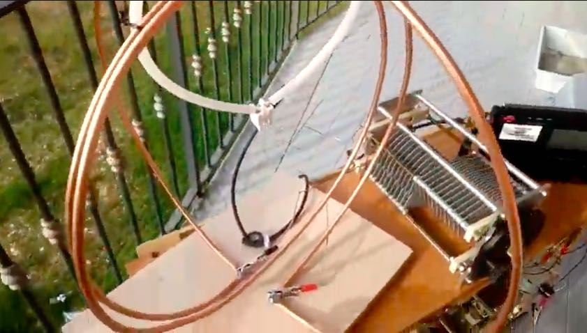
I am sending you this umpteenth project of mine built with poor materials…it is a test bench, loops / capacitors to find the best tuning.

The frame is a shoe rack in beech wood, very light, to take anywhere or to try out at home.
On the frame, there are 4 different loops of different sizes and 3 variable capacitors with different capacities. Only one signal transfer link to the receiver for all loops.

With alligator plugs I can use the different combinations of loop / variable to find the best tune

This test rig can tune the whole HF frequency range and medium wave.

I’ve attached 3 videos where you can see from the beginning to the last test on the balcony of my house.

Videos

Note that the following videos are in Italian, but you can turn on closed captioning and in the settings of the video have it auto-translate into the language of choice:

Click here to view on YouTube.

Click here to view on YouTube.

Click here to view on YouTube.

All, as always, spending very little and employing used materials!

Thanks to you and a warm greeting to the whole SWLing Post community.

I remain available for any clarification.

Greetings to all and good experimentation!

Thank you for sharing this Giuseppe! I love your ingenuity and spirit of experimentation! What a fun project that obviously yields excellent results!

Spread the radio love

Airspy HF+ Discovery & Shortwave Portables: Having Fun with the Airspy YouLoop!

Many thanks to SWLing Post contributor, Bill Hemphill, who shares the following guest post:

YouLoop Antenna Fun

by Billy Hemphill WD9EQD

Like many listeners, I live in an antenna restricted community.  While I have strung up some hidden outdoor wire antennas, I have found that they didn’t really perform that much better than just using the telescoping antenna with maybe a length of wire attached.  The biggest problem (whether indoor or outdoor antenna) has been the high noise floor.

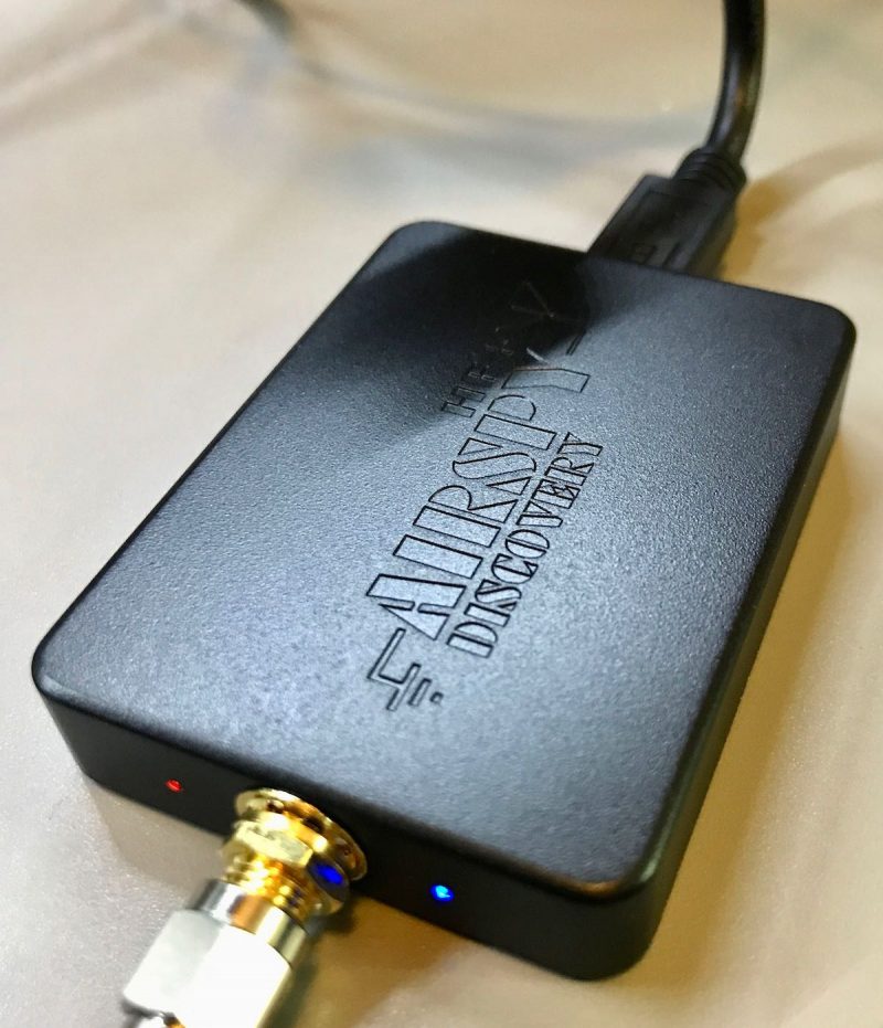
A few months ago I bought an AirSpy HF+ Discovery SDR receiver.  I had already owned a couple of SDRPlay SDR receivers, but the high noise floor limited their performance.  I had read good reviews about the AirSpy, especially its performance on the AM Broadcast band and the lower shortwave bands.

I have about 80 feet of speaker wire strung from the second floor and across the high windows in the living room.  This does perform fairly well, but the high noise floor still exists.

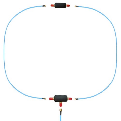
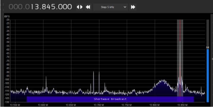
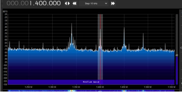
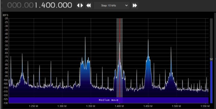
A couple of weeks ago, I bought the YouLoop Magnetic Loop antenna from AirSpy.  I gave it a try and am amazed at the lower noise floor compared to the indoor wire antenna.

Wire Antenna vs. YouLoop–some examples:
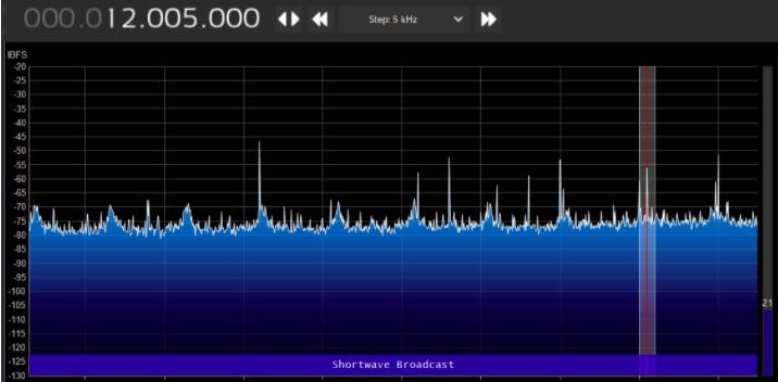
AirSpy with Wire Antenna

AirSpy with YouLoop

AirSpy with Wire Antenna
AirSpy with YouLoop
AirSpy with Wire Antenna
AirSpy with YouLoop

Dramatic reduction in the noise floor.  I’ve done a lot of playing around with it and find that the YouLoop picks up just about the same stations as the indoor wire antenna does.  But with the lower noise level, the YouLoop makes it more enjoyable to listen.  Overall, the YouLoop is now my main antenna.

YouLoop with a Portable Radio

It works so well with the AirSpy, I started wondering if I could use it with a portable radio, like the Tecsun PL-880.  But the AirSpy website has the following note:

Note: It is very likely your third party radio will not be sensitive enough to operate with the YouLoop properly. We have even seen self-documented failed attempts to build pre-amplifiers to compensate for the lack of sensitivity and/or the required dynamic range in third party radios. Use your brain, and eventually an Airspy HF+ Discovery.

Doesn’t sound like it will work with portable radios.  BUT, I’m always one to try anyway.
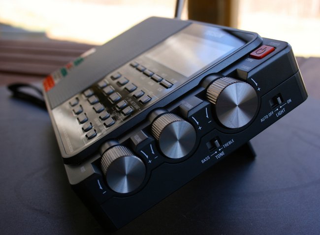
Tecsun PL-880

Since the YouLoop has a SMA connector, I bought a SMA to 1/8” phone jack cable.  Plugged it into the PL-880 antenna jack and found I had almost a dead radio.  Very few stations heard.  But in playing around, I accidentally touched the phone plug to the telescoping antenna and instantly got strong signals.

I did some very unscientific tests.  I attached the YouLoop through the side antenna jack, did an ATS scan, then did the same with the YouLoop clipped to the telescoping antenna.  Also did a scan with just the telescoping antenna fully extended..  I got some very interesting results.  These were done one after the other, so there can be differences in signal fading, etc.
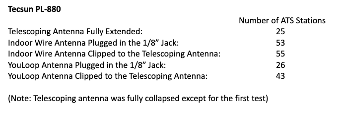
I have repeated the above test several times at different hours.  While the actual number of ATS stations varied, the ratio between them remained fairly consistent to the above numbers.

From the above, it appears that the telescoping antenna circuit is more sensitive than the 1/8” antenna jack circuit.  Maybe some attenuation is being added to the 1/8” jack since it’s more likely a higher gain antenna would be used there.  Can anyone confirm that the circuit indeed attenuates thru the antenna jack?

The YouLoop seems to be a decent performer when directly clipped to the telescoping antenna.  While not as good as a high gain outdoor antenna would be, it definitely is usable for indoor uses.

I also tested it clipped to the antennas of some other portable receivers. Tecsun S-8800, PL-330, Panasonic RF-2200 and Philco T-9 Trans-World receivers.  All showed an increase over just using the telescoping antenna.

Some interesting notes:

The Tecsun PL-330 saw the same reduction in signal when directly plugged into the antenna jack as opposed to clipping on the telescoping antenna.
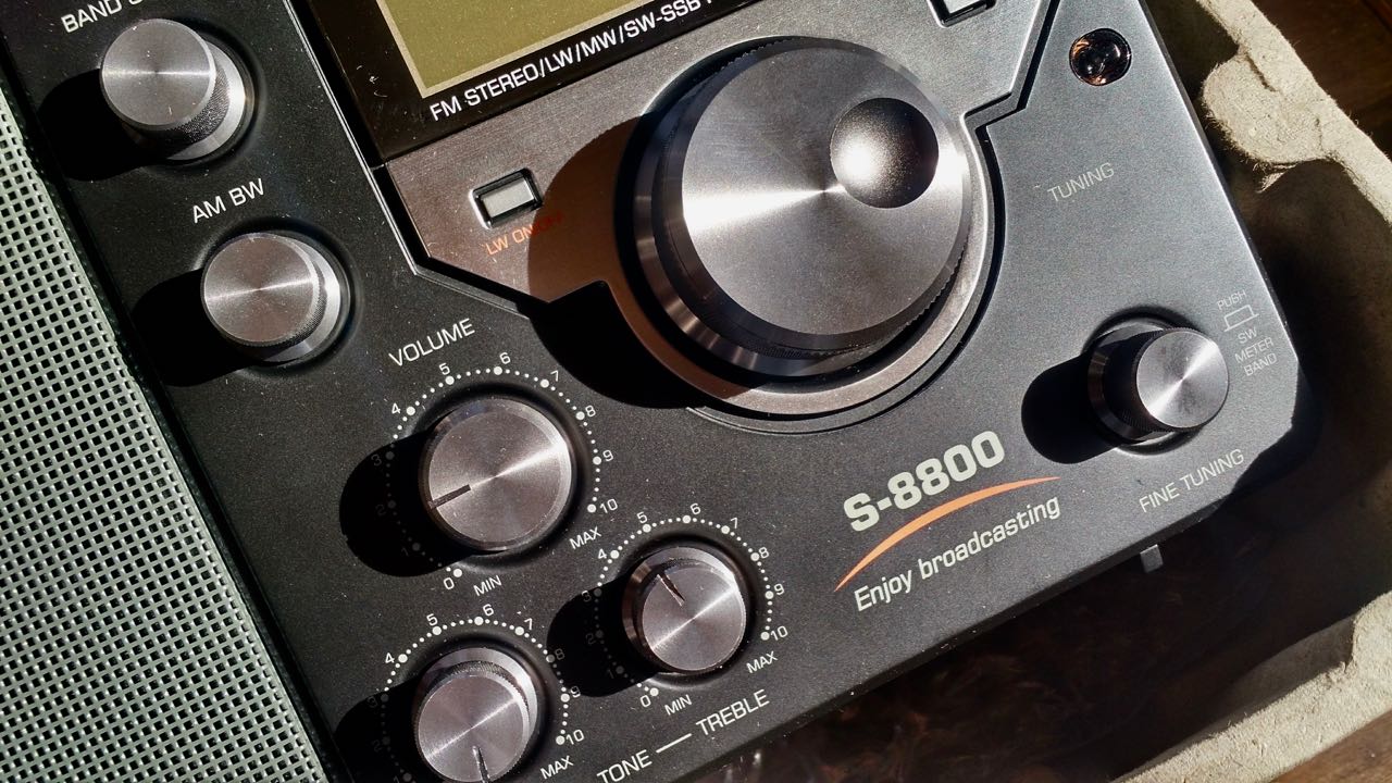
The Tecsun S-8800 did not show that much of a drop.  I basically got the same number of stations when clipped to antenna as when I connected to the BNC jack:

In conclusion, I find that I can use the YouLoop with my portable radios to increase the signals on strong stations when used indoors.  And it is quite the performer when used with the AirSpy HF+ Discovery SDR receiver.  It easily portable and I find that I move it around the house as I need to.  I just hang it off a window curtain rod.  I may just order a second one so that my family room radio has one permanently attached to it.

Click here to check out the Youloop at Airspy.com.
Spread the radio love

Dan compares the Chameleon CHA RXL to the Wellbrook and W6LVP Loops

Many thanks to SWLing Post contributor, Dan Robinson, for the following guest post and review:


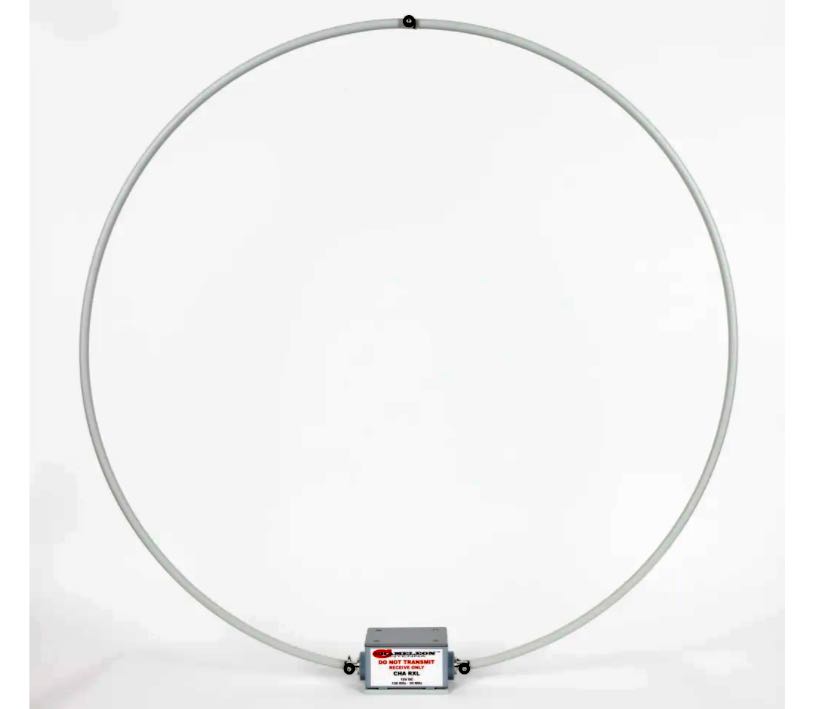
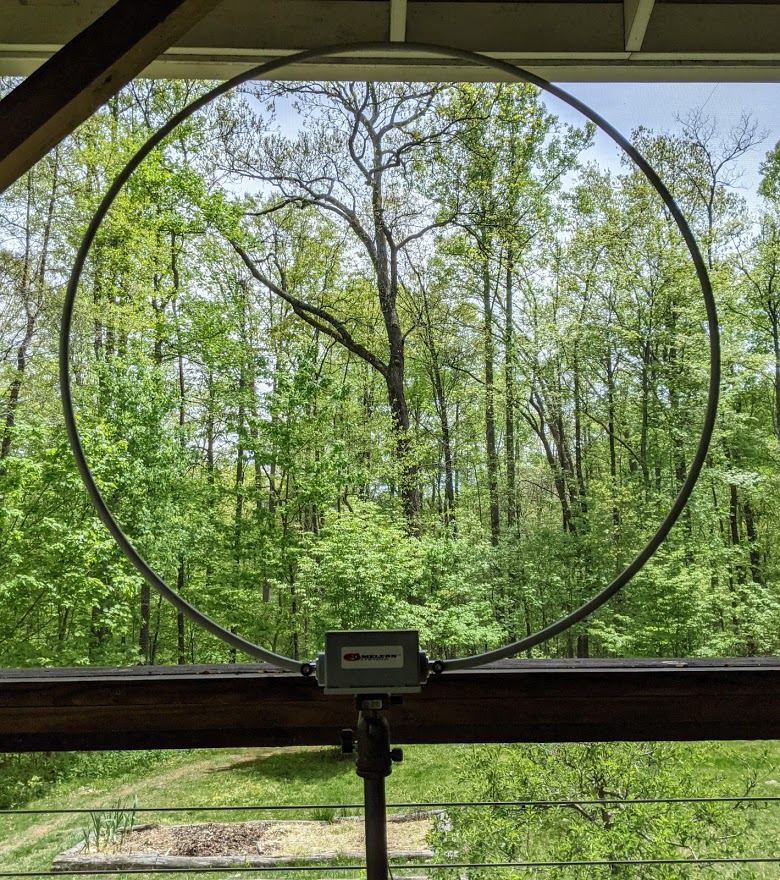
Chameleon CHA-RXL:  Is This Pro-level Loop A Worthy Competitor To Wellbrook and W6LVP?

by Dan Robinson

At the end of summer 2021, I took up an offer from Chameleon to test and review their CHA – RXL loop antenna.  The company describes this as a “new design high-performance” LF, MF, and HF receive-only loop perfect for mobile RV and apartment situations and with low noise characteristics.

This is not a cheap antenna, like the Chinese-made MLA-30, but a heavy duty professionally-built unit designed to, as the old TIMEX watch commercial said, “take a licking and keep on ticking”.

Price for the CHA RXL is around $500, though the company dropped the price at to $382 – but only for the two section loop rather than the single piece antenna advertised on its site.

You can see the Chameleon on the company’s website here, but it’s also sold by Gigaparts, DX Engineering and other radio suppliers.  Chameleon lists features as:

Highly directional, balanced input preamplifier to eliminate environmental noise and ground loops, receives on new 2200m and 630m ham bands, flexible mounting and power options, and a stealthy [36 inch] Navy gray loop [that] fades into the background sky.

The built-in preamplifier, says Chameleon, “will enable clearer reception than many large horizontal wire or vertical antennas.”  Weight of the amplifier is given as 7 lbs.  The large pre-amp box is made of heavy metal, with a rubber gasket seal. Continue reading

Spread the radio love

Video: Dave sets up the Chameleon CHA-RXL

Many thanks to SWLing Post contributor, Mike, who shares the following video from David Casler featurin the CHA RXL amplified loop antenna:

Click here to view on YouTube.

Thank you for the tip, Mike!

I just checked out the loop at Chameleon and discovered that they’re currently offering a sale on the “two sections” version of the CHA-RXL. Click here to check it out.

Also, if you live in Switzerland or Europe, Lutz Electronics is now a distributor of Chameleon products.

Spread the radio love

Bob’s Updated Passive, Resonant, Transformer-Coupled Loop Antenna for Shortwave

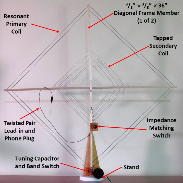
Figure 1. A Passive, Resonant, Transformer?Coupled Loop Antenna for Shortwave

Many thanks to SWLing Post contributor, Bob Colegrove, for the following guest post:


A Passive, Resonant, Transformer?Coupled Loop Antenna for Shortwave

By Bob Colegrove

Over the years I have resisted the level?of?effort necessary to construct and maintain outdoor antennas. Rather, I have focused on squeezing out all of the microvolts I could get inside the house. Many years ago I had access to a well?stocked engineering library, and used my advantage to gather information about the theory and development of loop antennas – a daunting undertaking for an English major. Ultimately, by adhering to a few basic rules, some of them dating back 100 years, I found quite acceptable performance can be had with an indoor passive antenna intersecting just a few square feet of electromagnetic energy.

Theory

There are a couple of advantages of resonant loops as opposed to non?resonant ones. The first is the fact that the signal dramatically increases when you reach the point of resonance. The second follows from the first in that resonance provides a natural bandpass which suppresses higher and lower frequencies. This gives the receiver a head start reducing intermodulation or other spurious responses. The downside of all this is that the resonant loop is, by design, a narrow?band antenna, which must be retuned every time the receiver frequency is changed by a few kHz. On the other hand, there is nothing quite as rewarding as the sight (S?meter) and sound you get when you peak up one of these antennas – you know when you are tuned in.

There is nothing new about the loop antenna described here. It’s just the distillation of the information I was able to collect and apply. There are a number of recurring points throughout the literature, one of which is the equation for “effective height” of a loop antenna. It basically comes down to the “NA product,” where N is the number of turns in the loop and A is the area they bound. In other words, provide the coil with as much inductance as possible.

Unfortunately, for resonant loops, the maximum coil size diminishes with frequency.
With this limitation on inductance, the challenge becomes minimizing unusable capacitance in the resonant frequency formula in order to get the highest inductance?to?capacitance (L/C) ratio possible. Some of the unusable capacitance is built into the coil itself in the form of distributed capacitance, or self?capacitance between the coil turns. This cannot be totally eliminated, but can be minimized by winding the coil as a flat spiral rather than a solenoid, and keeping the turns well separated.

The second trick is with the variable capacitor. Even with the plates fully open, there is residual capacitance on the order of 10 to 20 picofarads which can’t be used for tuning purposes. A simple solution is to insert a capacitor in series, about 1?4 the maximum value of the variable capacitor. This effectively decreases the minimum capacity and extends the upper frequency range. In order to restore the full operating range of the variable capacitor, the fixed capacitor can be bypassed with a ‘band switch.’ With the series capacitor shorted, the variable capacitor operates at its normal range and extends coverage to the lower frequencies. Continue reading

Spread the radio love