 In the past few weeks, I’ve gotten a lot of questions from readers who are trying to decide if they should install a magnetic loop antenna or a simple wire antenna at their home. Obviously, most of the questions come from shortwave radio listeners, but some have come from ham radio operators as well.
I realize that there’s a common theme to my answers and I thought it might be useful to share it here on the SWLing Post for future reference. I started to write a slightly more comprehensive article about this, but I quickly realized I want to keep my advice as short and clear as possible. I’ll be painting in broad brush strokes, but here you go:
If you live in an environment with a lot of radio interference…
Magnetic loop antennas are your friend.
By design, mag loop antennas are some of the best antennas for mitigating the radio frequency interference (RFI) that plagues so many of our homes and neighborhoods. When oriented vertically, mag loop antennas can also be rotated to null out unwanted signals on lower frequencies.
Mag loops come in a wide variety of configurations:
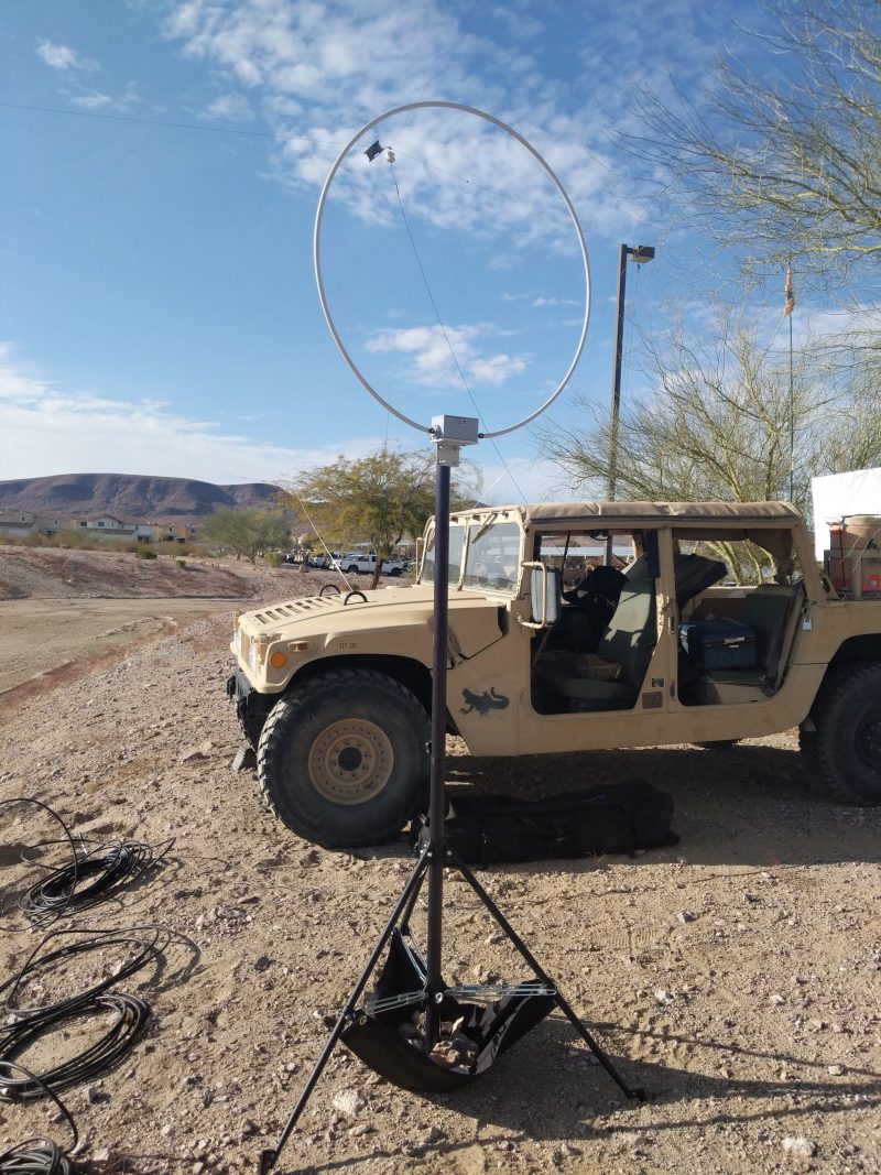
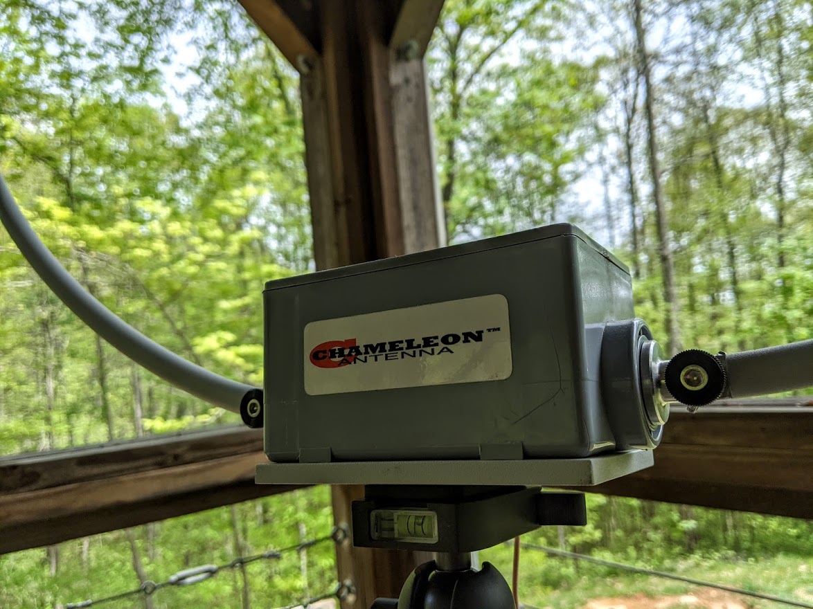
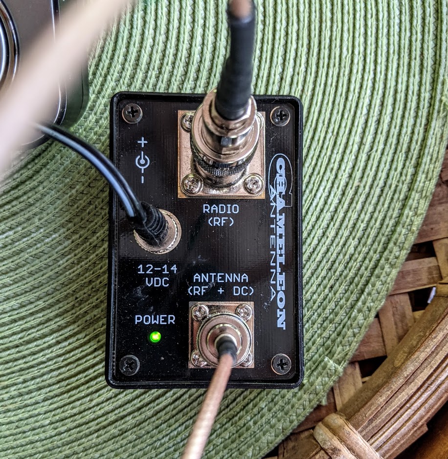
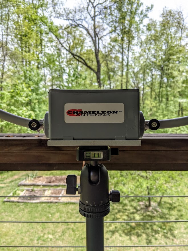
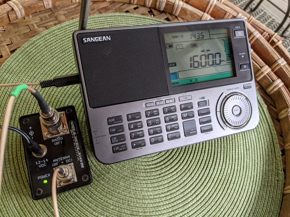
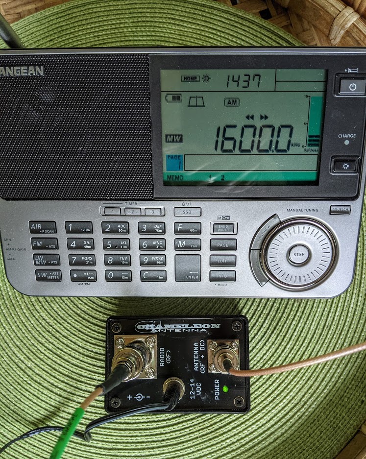
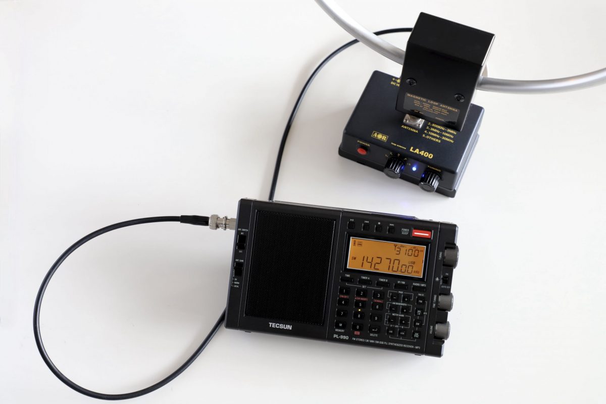
- The most popular among SWLs are wideband amplified loop antennas manufactured by companies like Wellbrook, Chameleon Antenna, MFJ, DX Engineering, Cross Country Wireless, Bonito, and a number of manufacturers in China. Unlike passive loop antennas, wideband amplified antennas require no manual tuning. These loops do require a power source, typically fed through a Bias-T or batteries.
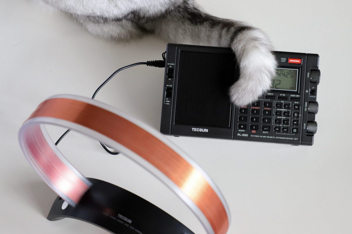
- Passive loop antennas are popular among ham radio operators because they’re easy to build and, unlike amplified loop antennas, one can transmit into them if designed correctly. They’re less popular among radio listeners only because they typically have a very narrow bandwidth and need to be re-tuned (via a variable capacitor) each time you move frequency even a few kilohertz. The NCPL (Noise-Cancelling Passive Loop) which is also known as the Moebius or YouLoop is a bit of an exception and doesn’t require tuning, but does require a receiver with a very high dynamic range.
Loop antennas can also be very stealthy. In fact, Loop on Ground (LoG) antennas are essentially invisible and could be deployed (under the cover of darkness, of course!) in the most restrictive of neighborhoods. Note that since LoGs are horizontal, they are essentially omni-directional. [13dka corrects this in the comments: “This is somewhat ambiguous and not entirely correct: LoGs are horizontally oriented but (somewhat surprisingly) vertically polarized, and even more surprisingly they have the trademark property of verticals”]
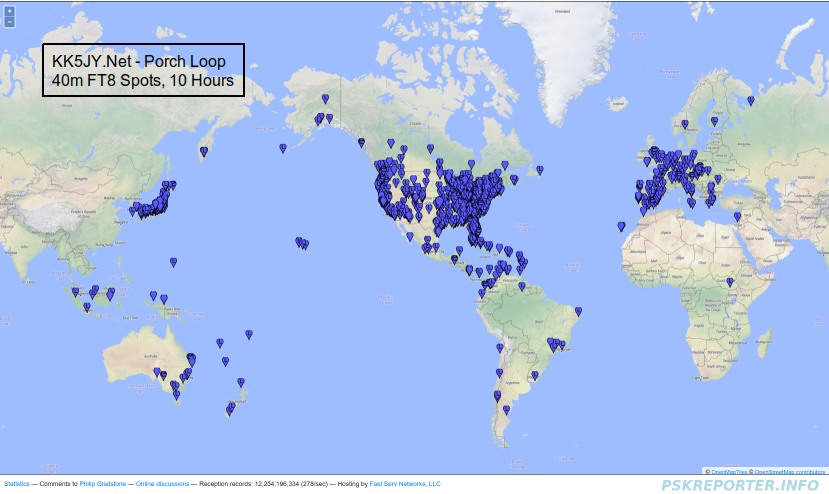
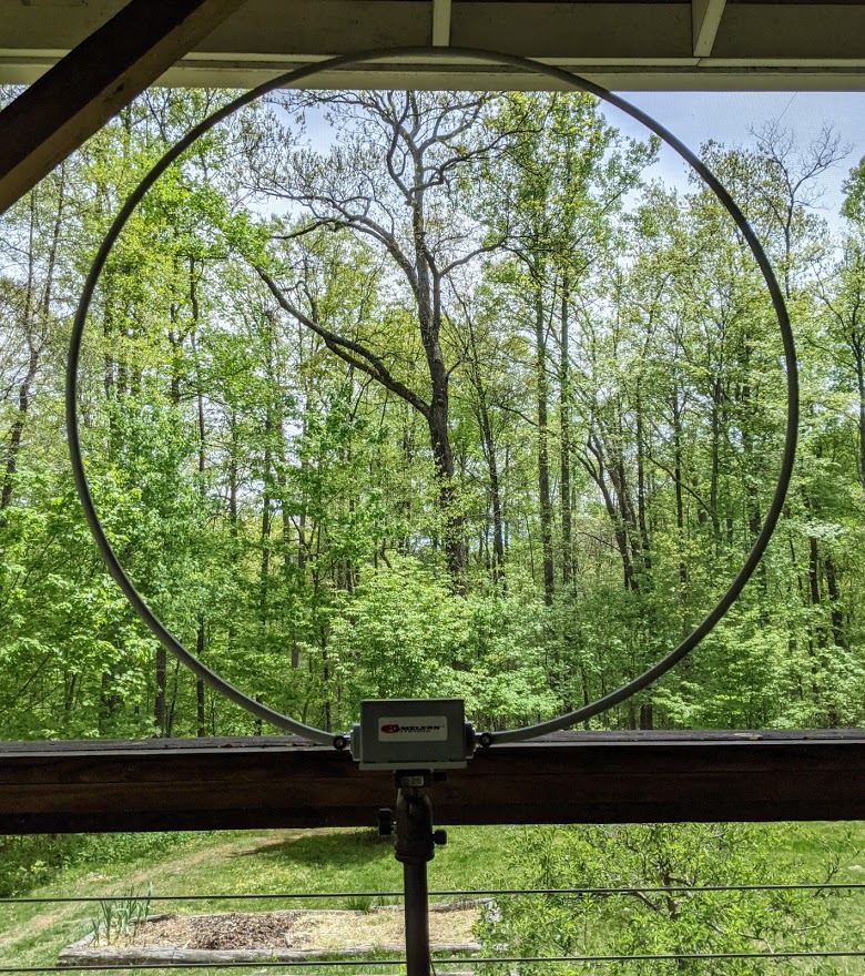
We’ve also featured other stealthy loop designs like this porch loop.
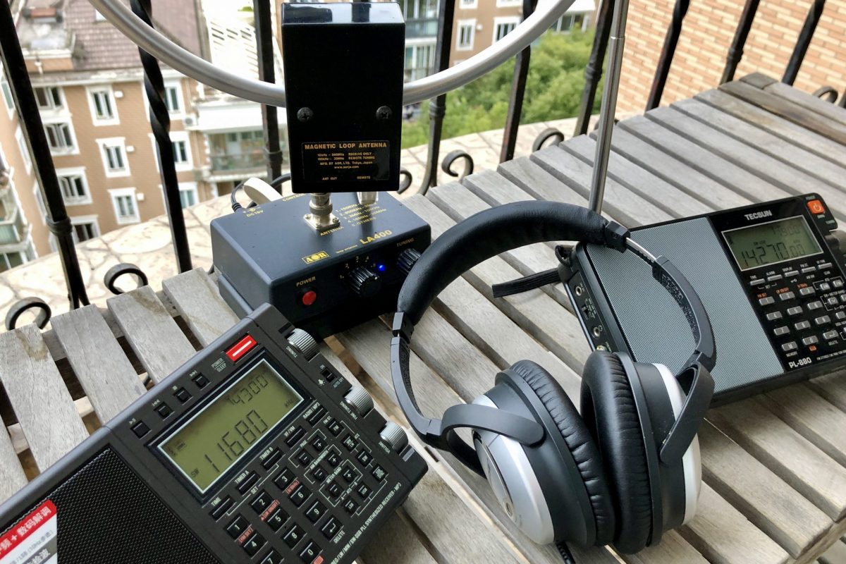
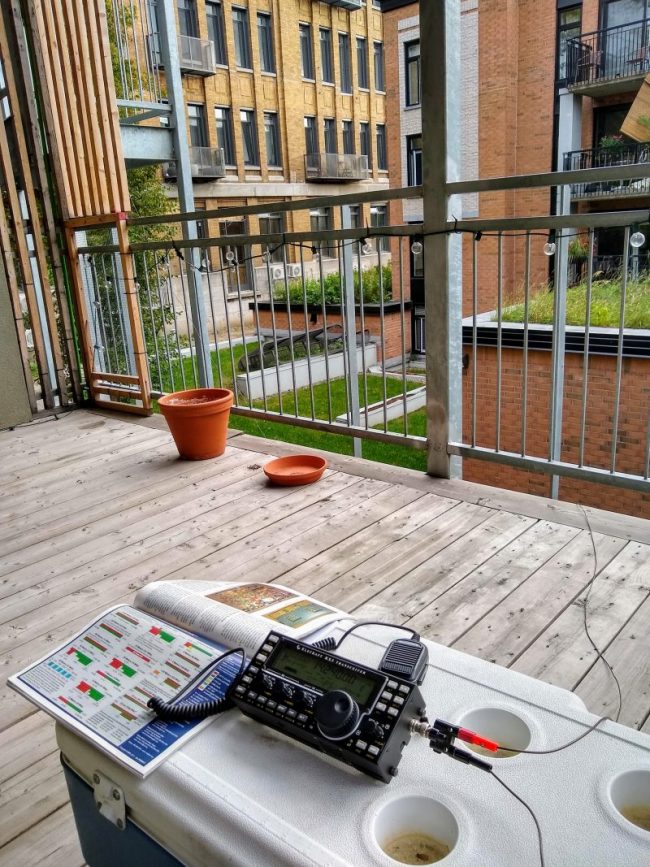
As with any antenna, mag loops prefer to be outdoors but can be effectively used indoors if that’s the only option.
If you live in an environment free of radio interference…

Outdoor wire antennas are very hard to beat.
I am a case in point, in fact: I live in a rural, remote location without any meaningful RFI. All of my external antennas are homebrew wire antennas and they serve me incredibly well.
If you’ve been a reader for long, you may note that I don’t personally review amplified magnetic loop antennas often–these are typically published by some of our amazing contributors. This is because I like to do “apples to apples” comparisons and usually don’t have a second compact magnetic loop antenna for comparison here at SWLing Post HQ.
Almost without exception, my cheap homebrew wire antennas outperform wideband amplified mag loop antennas…sometimes, by orders of magnitude.
Many years ago, I tested a Pixel Loop amplified mag loop antenna (now under a different name and sold by DX Engineering) specifically for use on the mediumwave band to null unwanted stations. It was a very capable amplified mag loop antenna, but other than its MW nulling abilities, all of my homebrew wire antennas outperformed it on the HF bands. Reception was, at times, dramatically better on my wire antennas.
Of course, for a wire antenna to perform properly, it needs to be deployed properly. There are excellent resources out there that describe ideal heights and configurations for any given wire antenna design.
Keep in mind that wire antennas can be incredibly stealthy as well. It’s very difficult to see a wire antenna among or in front of a patch of trees, for example. At a previous home, I deployed a horizontal delta loop antenna on my property that–if you knew where to look–was easy to spot from the road. In all of the years we lived there not one neighbor took note, though, because the antenna wire had sky blue jacketing and I deployed it while no one was looking.
Summary
 Experiment!
This isn’t an either/or choice for most of us. There’s no harm in building a simple wire antenna and trying it at home first. If the local noise floor is high, then consider adding a magnetic loop antenna to your arsenal as well.
You might find that the wire antenna has an advantage on frequencies where you have less radio interference, and the mag loop serves you well in those portions of the band with thicker RFI and QRM.
Find the best antenna system that works for you at home, but always remember that hitting the field with your radio has advantages as well!
What did I miss?
I omitted numerous antenna designs that aren’t straight-forward loop or simple wires. Check out some designs by our contributors Grayhat, Giuseppe Morlè (IZ0GZW), TomL, and many others here on the SWLing Post. As always, please feel free to comment!