We recently posted a tutorial on building a simple Noise-Cancelling Passive Loop (NCPL) antenna. This prompted SWLing Post contributor, Bob Colegrove, to share his excellent article on building a Passive, Resonant, Transformer-Coupled Loop (PRTCL) Antenna:
A Passive, Resonant, Transformer-Coupled Loop Antenna for Shortwave
By Bob Colegrove
Over the years I have resisted the level-of-effort necessary to construct and maintain outdoor antennas. Rather, I have focused on squeezing out all of the microvolts I could get inside the house. Many years ago I had access to a well-stocked engineering library, and used my advantage to gather information about the theory and development of loop antennas – a daunting undertaking for an English major. Ultimately, by adhering to a few basic rules, some of them dating back 100 years, I found quite acceptable performance can be had with an indoor passive antenna intersecting just a few square feet of electromagnetic energy.
Theory
There are a couple of advantages of resonant loops as opposed to non-resonant ones. The first is the fact that the signal dramatically increases when you reach the point of resonance. The second follows from the first in that resonance provides a natural bandpass which suppresses higher and lower frequencies. This gives the receiver a head start reducing intermodulation or other spurious responses. The downside of all this is that the resonant loop is, by design, a narrow-band antenna, which must be retuned every time the receiver frequency is changed by a few kHz. On the other hand, there is nothing quite as rewarding as the sight (S-meter) and sound you get when you peak up one of these antennas – you know when you are tuned in.
There is nothing new about the loop antenna described here. It’s just the distillation of the information I was able to collect and apply. There are a number of recurring points throughout the literature, one of which is the equation for “effective height” of a loop antenna. It basically comes down to the “NA product,” where N is the number of turns in the loop and A is the area they bound. In other words, provide the coil with as much inductance as possible. Unfortunately, for resonant loops, the maximum coil size diminishes with frequency.
With this limitation on inductance, the challenge becomes minimizing unusable capacitance in the resonant frequency formula in order to get the highest inductance-to-capacitance (L/C) ratio possible. Some of the unusable capacitance is built into the coil itself in the form of distributed capacitance, or self-capacitance between the coil turns. This cannot be totally eliminated, but can be minimized by winding the coil as a flat spiral rather than a solenoid, and keeping the turns well separated.
The second trick is with the variable capacitor. Even with the plates fully open, there is residual capacitance on the order of 10 to 20 picofarads which can’t be used for tuning purposes. A simple solution is to insert a capacitor in series, about ¼ the maximum value of the variable capacitor. This effectively decreases the minimum capacity and extends the upper frequency range. In order to restore the full operating range of the variable capacitor, the fixed capacitor can be bypassed with a ‘band switch.’ With the series capacitor shorted, the variable capacitor operates at its normal range and extends coverage to the lower frequencies.
Construction
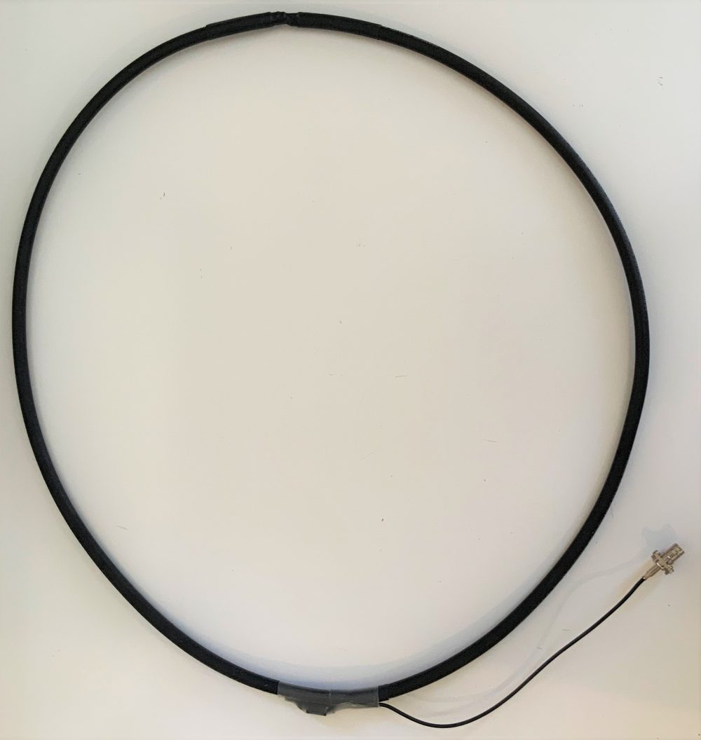
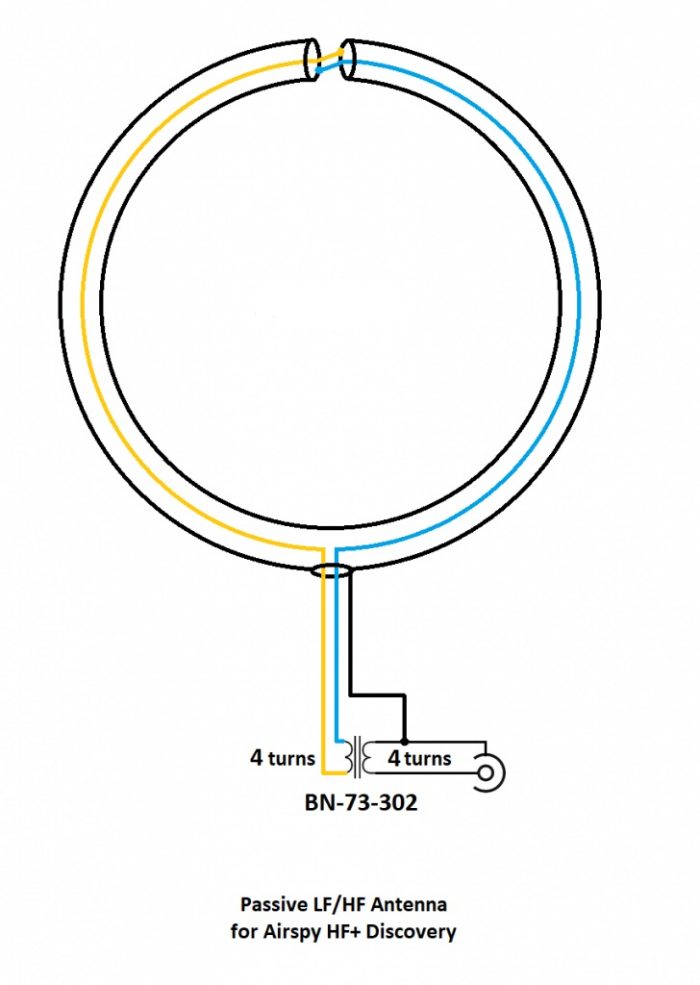
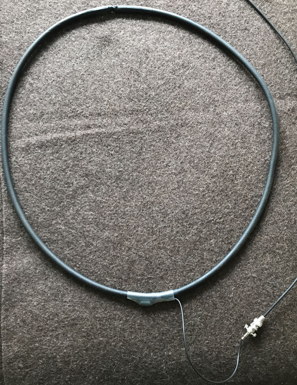
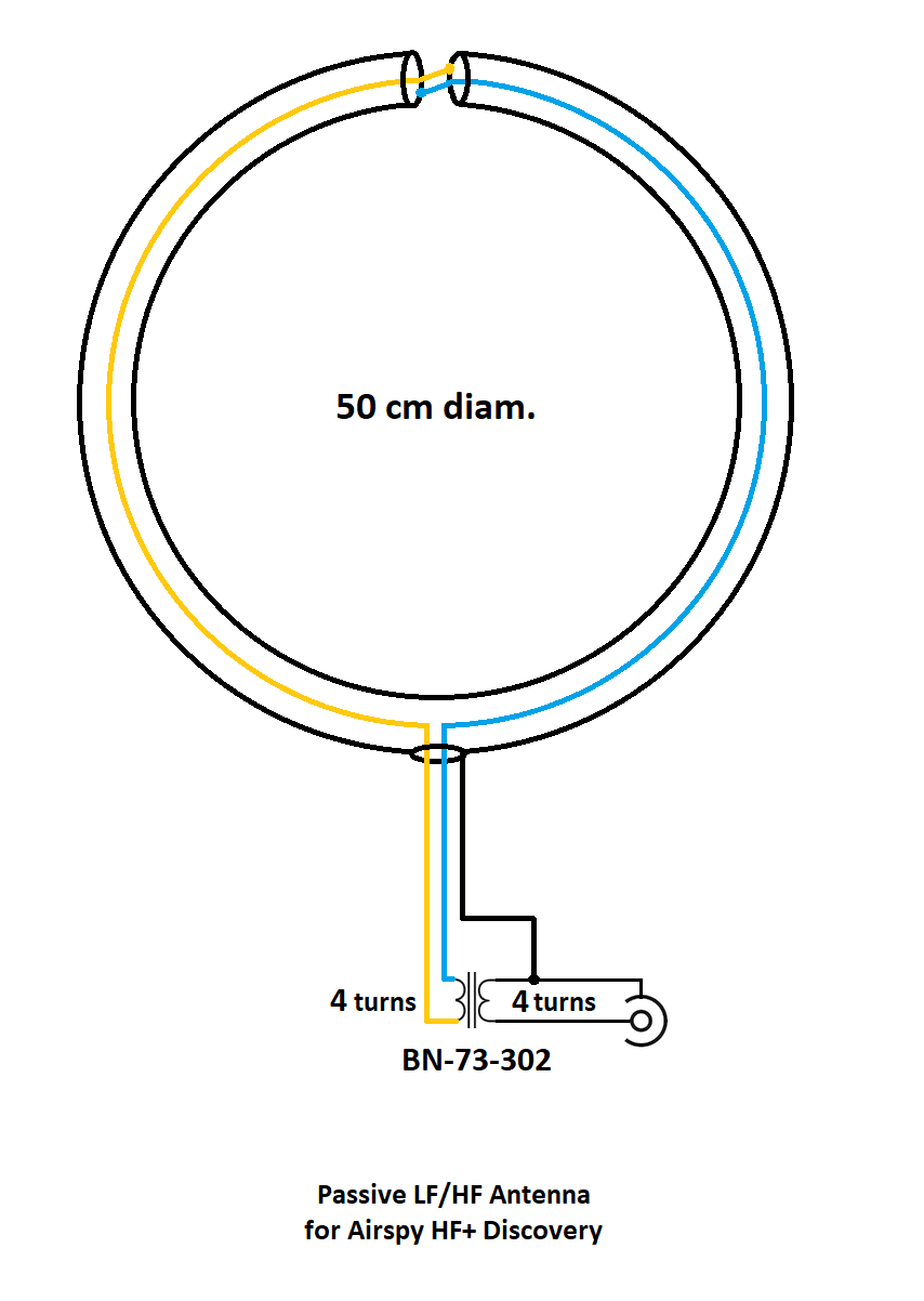
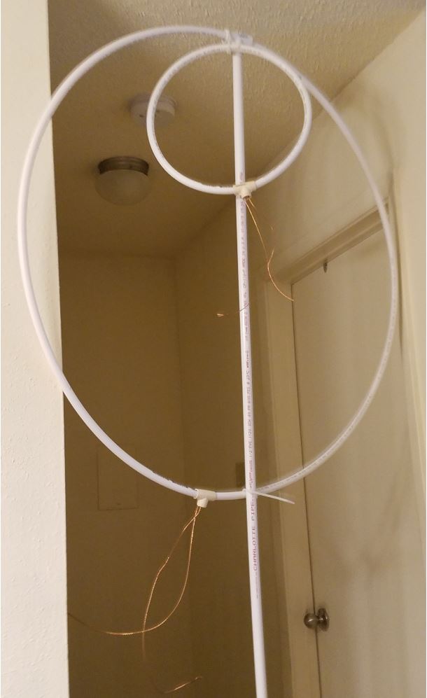
I have constructed similar loops covering long wave, medium wave, and shortwave all the way up to about 23 MHz. I wanted to optimize this loop for the most active portion of the shortwave spectrum. Consequently, it covers approximately 2.6 to 12.3 MHz. See Figure 1.
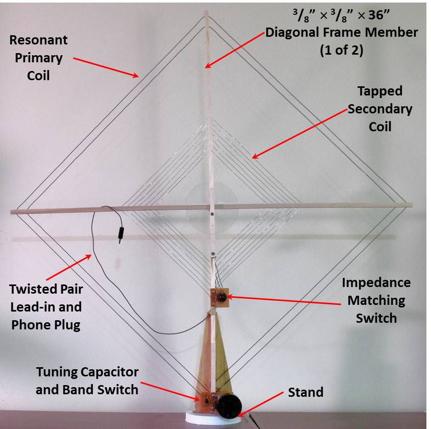
Figure 1. A Passive, Resonant, Transformer-Coupled Loop Antenna for Shortwave
Figure 2 is a schematic diagram of the antenna. Cd (in red) is the distributed capacitance of the primary coil, L1. This is not tunable capacitance, but it still contributes to the resonance; likewise, the 15 pf minimum capacitance of C1. By adding C2, the minimum total capacitance can be lowered to greatly increase the upper range of the antenna. S1 is the ‘band switch.’ It shorts out the series capacitor, restoring the maximum low frequency.
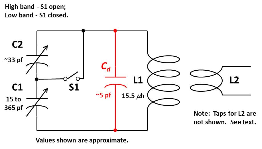
Figure 2. Schematic Diagram
Frame – The frame is made from 3/8”-square basswood or poplar dowel (see Specialized Parts). Two pieces, each 36” long, have been predrilled at ½” intervals to accommodate the primary and secondary coil wire (think of a tennis racket). It is a good idea to drill holes along the length of each dowel – more than you will need. You may decide to change things later on, and drilling holes in an assembled antenna is not easy. Also the two dowels are notched in their centers to fit together. See Figure 3 and Figure 4. The clear plastic disk in Figure 4 is a packing disk from a spindle of CDs; it is cemented to the square dowels, and used to hold them at right angles. Any rigid, light-weight material will do.
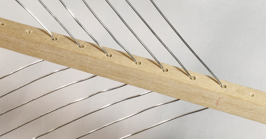
Figure 3. Square Dowel Showing 1?2” Hole Spacing and Lacing of Secondary Coil
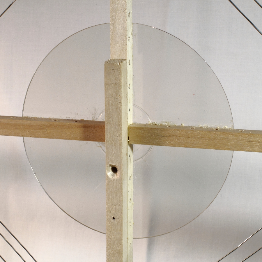
Figure 4. Cross Members Notched and Square Dowel Reinforcement
Primary Coil – With a coil size 36” in diameter, you likely won’t be able to get more than two turns of wire to resonate at frequencies up to 12 MHz. This takes into account the precautions described above to minimize unusable capacitance. AWG 22 stranded, insulated wire was used to lace this coil; ensure the dowels remain at right angles with one another. Note that one set of holes in the dowel is skipped between the first and second turn.
Tuning Capacitor – Almost any salvaged variable capacitor can be made to work. For a typical 2-gang unit, the gangs can be connected in series through the common rotor sections and metal frame with the stator terminals of each gang used as the outer terminals. This will create a lower minimum capacitance as described above.
For the antenna described here, a single-gang, 365-pf capacitor (see Specialized Parts) was used with a fixed mica capacitor in series. The minimum capacitance of the variable capacitor is nominally 15 pf. Figure 5 shows the capacitor assembly for the primary circuit. Components are mounted on a perforated circuit board, which, in turn, is mounted to the bottom of the vertical square dowel. A portion of the base can be seen at the rear. A large diameter tuning knob is suggested, as the peak tuning for a properly constructed loop will be very sharp and require a delicate touch. As an option, I have used a planetary reduction mechanism on other antennas to give an 8:1 ratio with the capacitor shaft.
You may notice at high frequencies that the antenna is somewhat unstable with body contact of the knob or around the tuning capacitor. This is because the resonant circuit is operating at a very high L/C ratio with capacitance at just a few picofarads. Body capacitance will tend to detune the antenna. It may be useful to extend the knob 2 or 3 inches from the tuning capacitor with an insulated shaft.

Figure 5. Capacitor Assembly
Secondary Coil – The secondary coil operates at low impedance to feed the lead-in. There are two extremes governing the size of the secondary coil. A coil which is too small will not pick up much of the magnetic field generated by the primary circuit at resonance. On the other hand, a secondary coil which is too large will overcouple or load the primary circuit. This will reduce the Q, or sharpness of the tuning.
The secondary coil is 16” diagonal at the largest turn and consists of 7 turns of AWG 20 buss wire. Buss wire was used so the coil can easily be tapped after the 1st, 2nd, 3rd, 4th, and 6th turn. The 7th turn is not currently used. A tapped coil will provide better impedance matches to the lead-in when the antenna is used through a wide frequency range. The taps are selected with a rotary switch. The taps are connected so that the outer turns are used first, and inner turns connected as needed. It is important that unused turns remain unconnected (free) rather than shorted. See Figure 6.
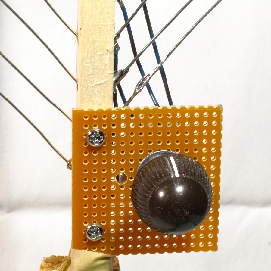
Figure 6. Secondary Coil Switch
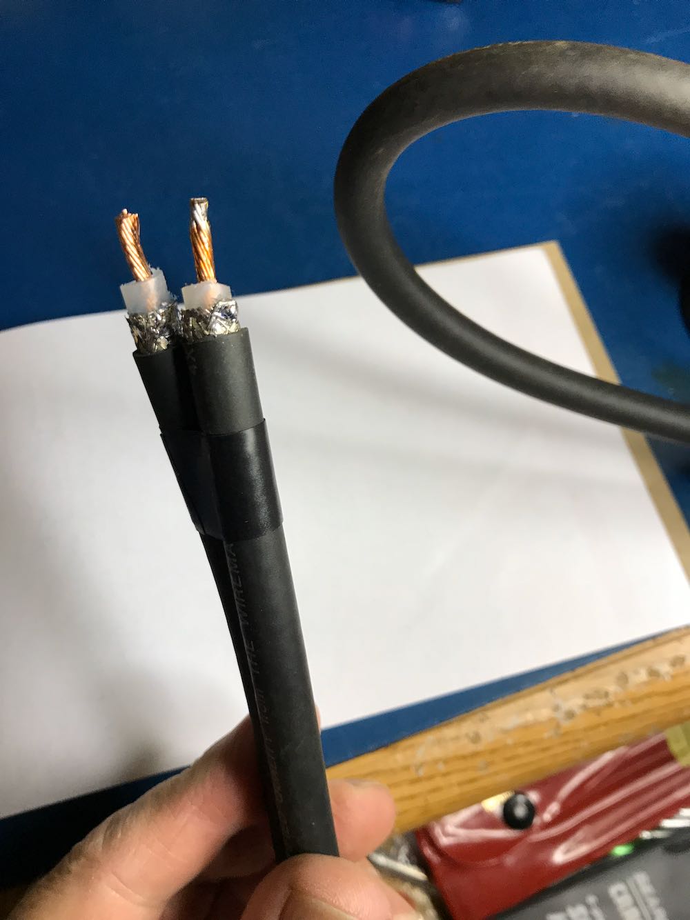
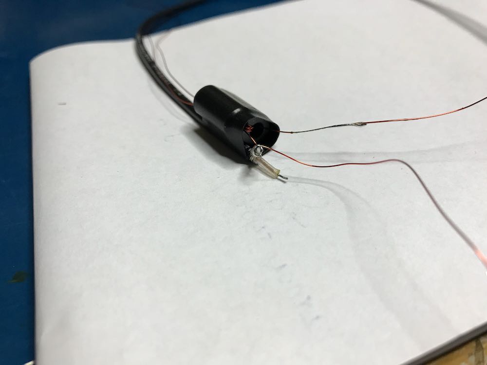
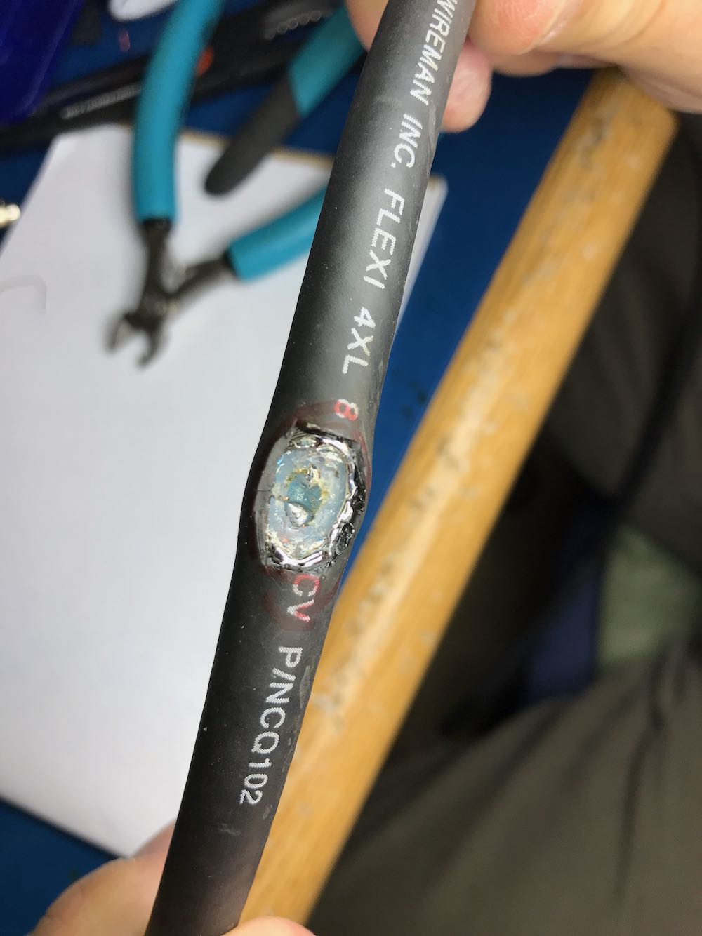
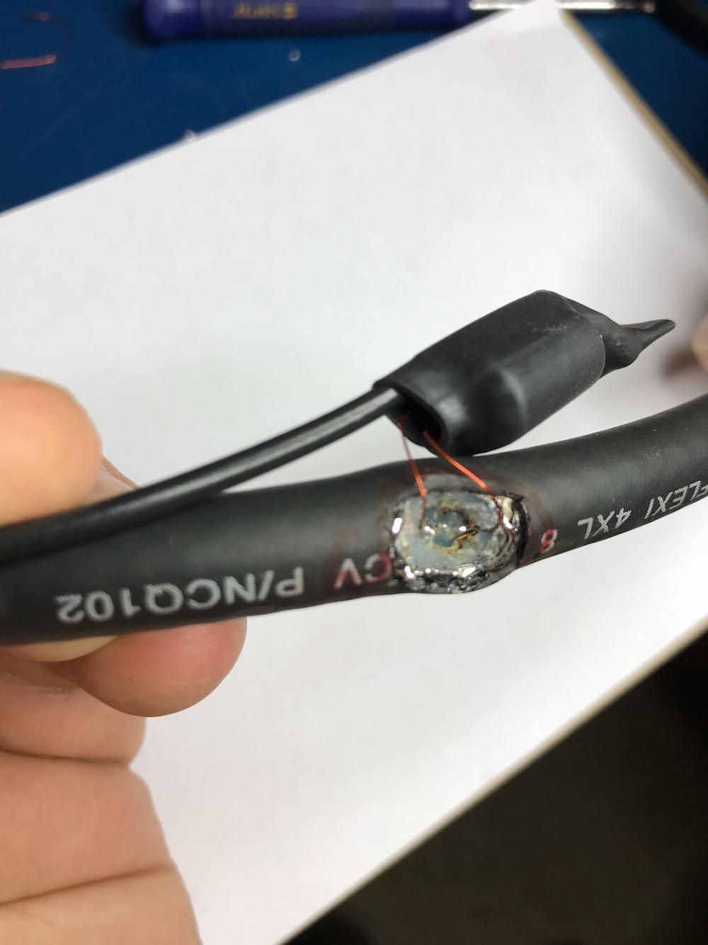
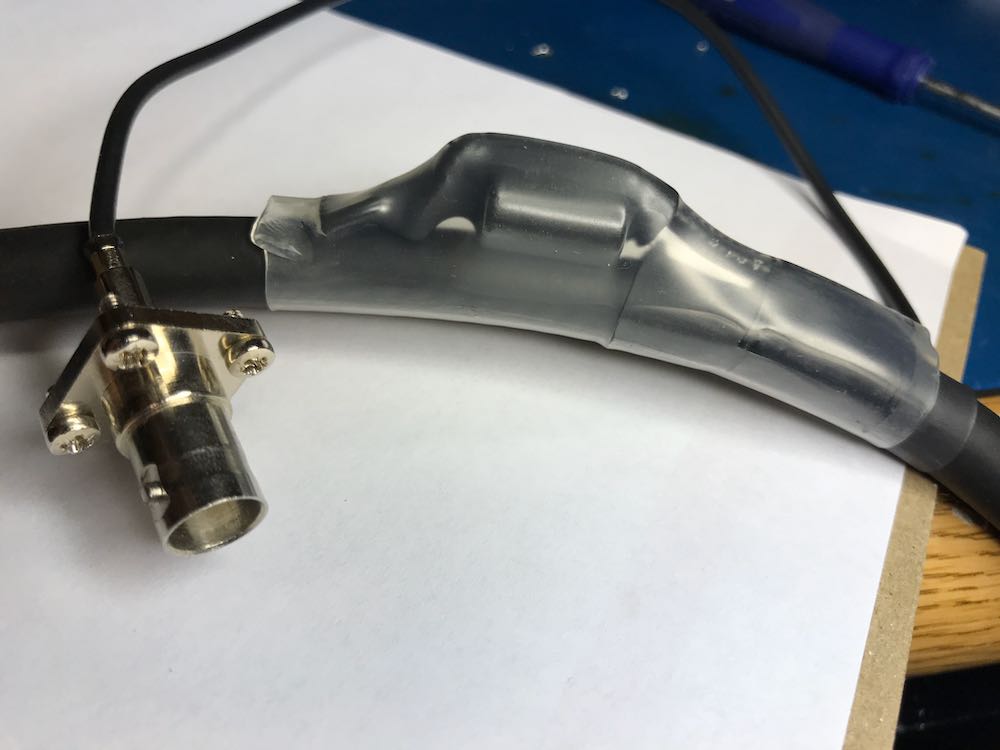
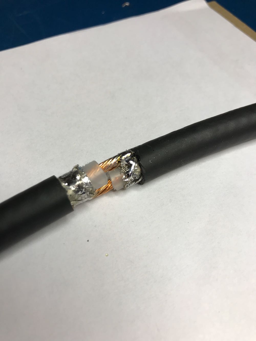
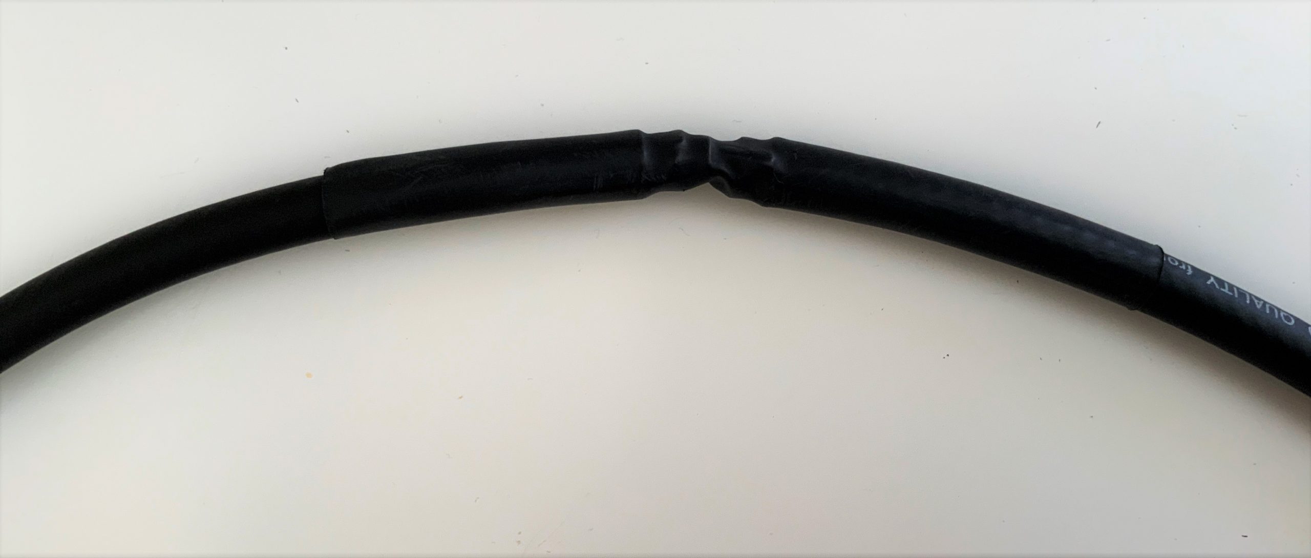
Lead-in – A twisted pair of AWG 22 stranded wire is used as the lead-in. This will be more flexible than coax. The lead-in should be kept as short as possible and twisted tightly so it will not pick up any signal by itself. This is important at shortwave frequencies. A twisted pair can be fabricated from two lengths of wire with one set of ends anchored in a vise, while the remaining ends are twisted in the chuck of a hand drill. Most portable radios are equipped with a standard 1/8” phone jack at the external antenna connection point. So, this antenna is terminated with a 1/8” phone plug.
Base – There is nothing special about the base. Your only guidance should be to make it as stable as possible. Since the frame is light, most of the weight will be at the bottom with the capacitor assembly and other parts. That helps stability. This antenna uses a 5” plastic jar lid for the bottom. Keep the base small, as the antenna will likely be operated on a desk or table.
Operation
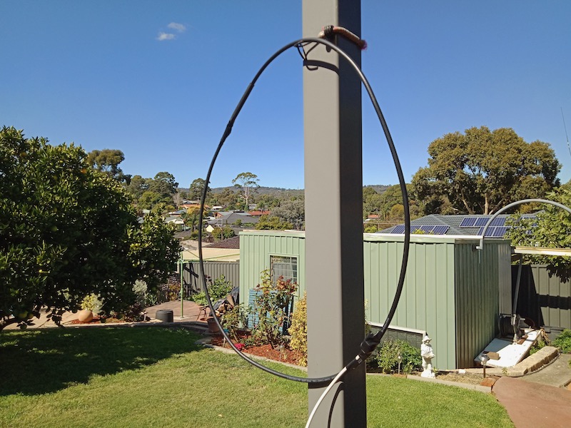
The antenna is intended to operate in close proximity to the radio, such as on a desk or table. There must be sufficient space to rotate the loop laterally. As described, this antenna has a range of 2.6 MHz through 12.3 MHz with a band overlap around 8 MHz. Depending on your selection of capacitors, your range and overlap may be slightly different.
- Tune the receiver to a desired frequency.
- Set the band switch on the antenna to the corresponding band.
- Tune the antenna capacitor to resonance (peak signal).
- Rotate the secondary switch to the position of maximum signal strength. Begin with the fewest turns (generally one) in the secondary.
- It may be necessary to repeak the primary circuit.
Repeat the procedure to test operation of the upper or lower band.
Unlike similar loops for long and medium wave reception, this antenna is not especially responsive to direction for peak or null signal reception. However, you will find it very useful to reduce or possibly eliminate locally produced noise. Simply rotate the antenna on its base.
Modification
The basic concept for this antenna can easily be extended to higher or lower frequencies. Removal of the inner turn of the primary will significantly raise the upper frequency; whereas, adding turns will increase the lower range. Note that the lacing of the primary coil skips one set of holes in the square dowels between the first and second turn. This minimizes distributed capacitance between turns. This separation should be maintained if additional turns are added to lower the operational frequency.
Specialized Parts
Some sources for square wood dowel and single-gang 365 pf variable capacitors are listed below. The author does not endorse any of them. Prices for similar capacitors vary widely.
Square wood dowel:
Variable capacitor (365 pf):
- Amazon
- Walmart
- Tubes and More
- MTM Scientific
- eBay (Multiple sources for both single- and double-gang capacitors)
Bob, thank you so much for sharing this excellent, detailed tutorial. Although I don’t have the exact same variable capacitor, I have all of the other components to make this antenna. I will have to put this on my Social DX bucket list! Thank you again!
Do you enjoy the SWLing Post?
Please consider supporting us via Patreon or our Coffee Fund!
Your support makes articles like this one possible. Thank you!