Many thanks to SWLing Post contributor, Kostas (SV3ORA), for sharing the following guest post which originally appeared on his radio website:
How to install a mechanical SSB filter on the Yaesu FRG-7
by Kostas (SV3ORA)
The Yaesu FRG-7 is a general coverage MW/SW receiver that uses the Wadley Loop system for stabilizing the frequency tuning. The receiver has a good sound on AM mode, that reminds me the tube receivers sound. However, on sideband mode, it is pretty much useless. The IF ceramic filter that is used, does not have enough selectivity to reject the opposite sideband. No matter if the front panel mode selector switch states USB/CW and LSB, these just shift the BFO, nothing more. The receiver is a DSB set not SSB. A cheap way you can accomplish single signal sideband reception with the FRG-7 is described in this link. Whereas it works, it increases the audio bandwidth of the signals to the high pitch.
A better approach is to install an additional mechanical filter to the receiver. This of course requires expensive 455KHz mechanical filters, but if you have one in hand or if you are willing to pay for the improvement in performance, then this is the recommended option. But you can’t just desolder the ceramic filter of the receiver and solder a mechanical filter in place. On AM mode, you need wider bandwidth, but on SSB mode you need narrower. So both filters must be in place and a selection must be done in each mode. Thankfully, this modification is pretty easy on the FRG-7 and it does not require any modification of the external appearance of the radio.
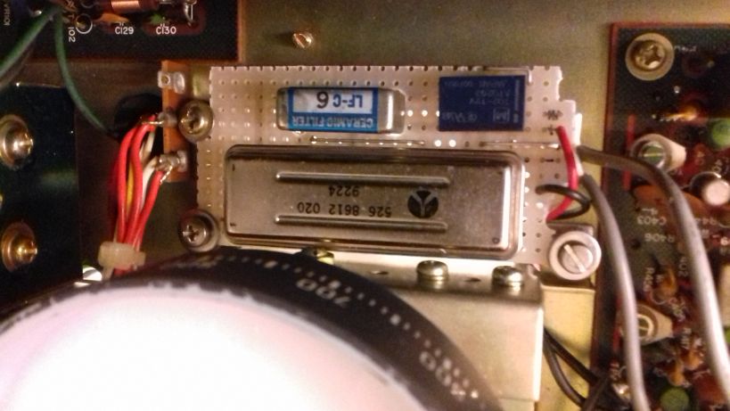
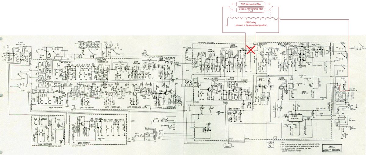 The schematic of the FRG-7 is shown above. Everything with red color, are part of the modification. The modification is pretty straight forward. You have to desolder the original ceramic filter from the FRG-7 PCB and install it on a separate PCB along with the new 455KHz mechanical filter. To select between the two filters, a 9-12v DPDT relay can be used and it must be connected as shown in the schematic. The power for the relay coil is derived from one section of the mode switch (S3d). On USB or LSB modes, the BFO is energized and this power is also used to energize the relay, which in turn switches to the narrow mechanical filter on these modes.
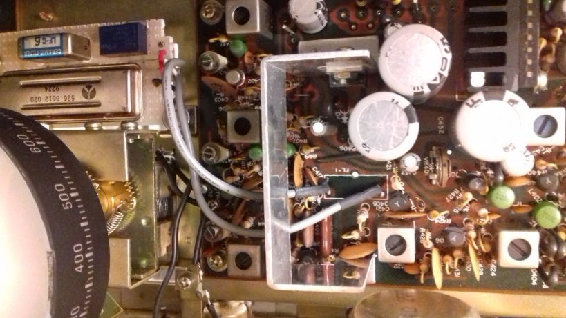
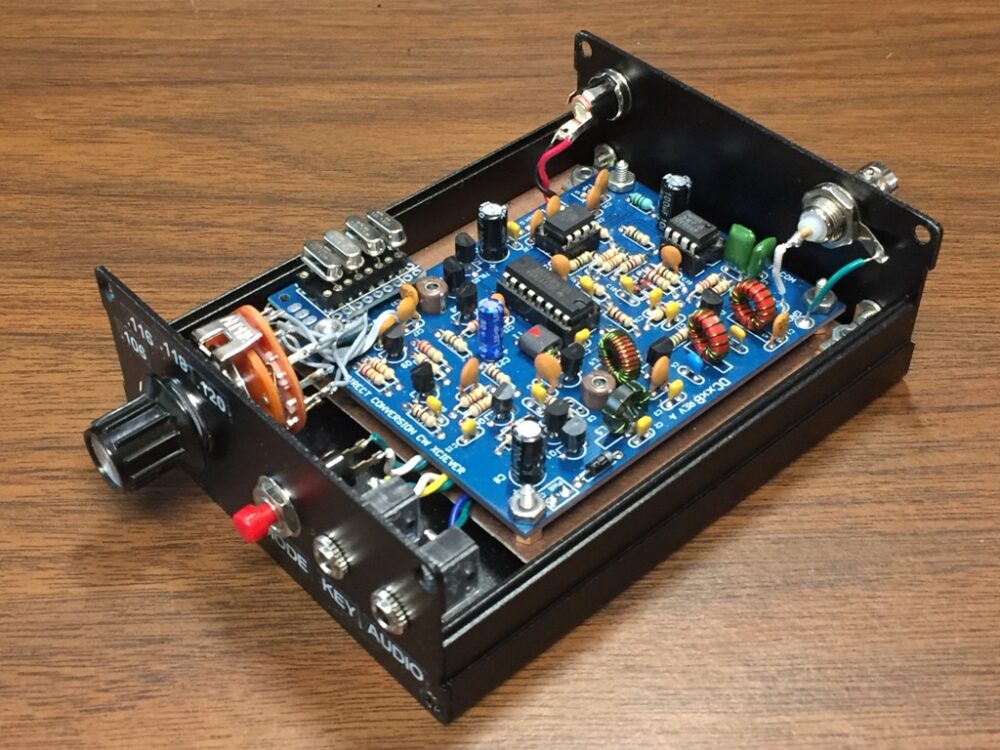
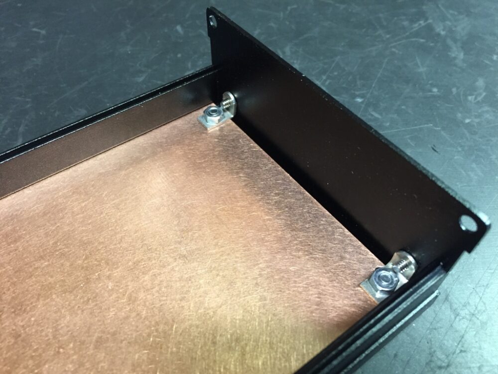
A good place for the new PCB that accommodates the filters, is just below the main tuning dial of the receiver. There is a hole there and three screws, which can be used to also hold this PCB in place. I needed to replace these screws in mine with longer ones, because I used spacers to prevent the PCB from touching the chassis. But this is optional.
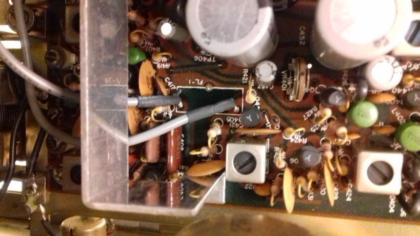
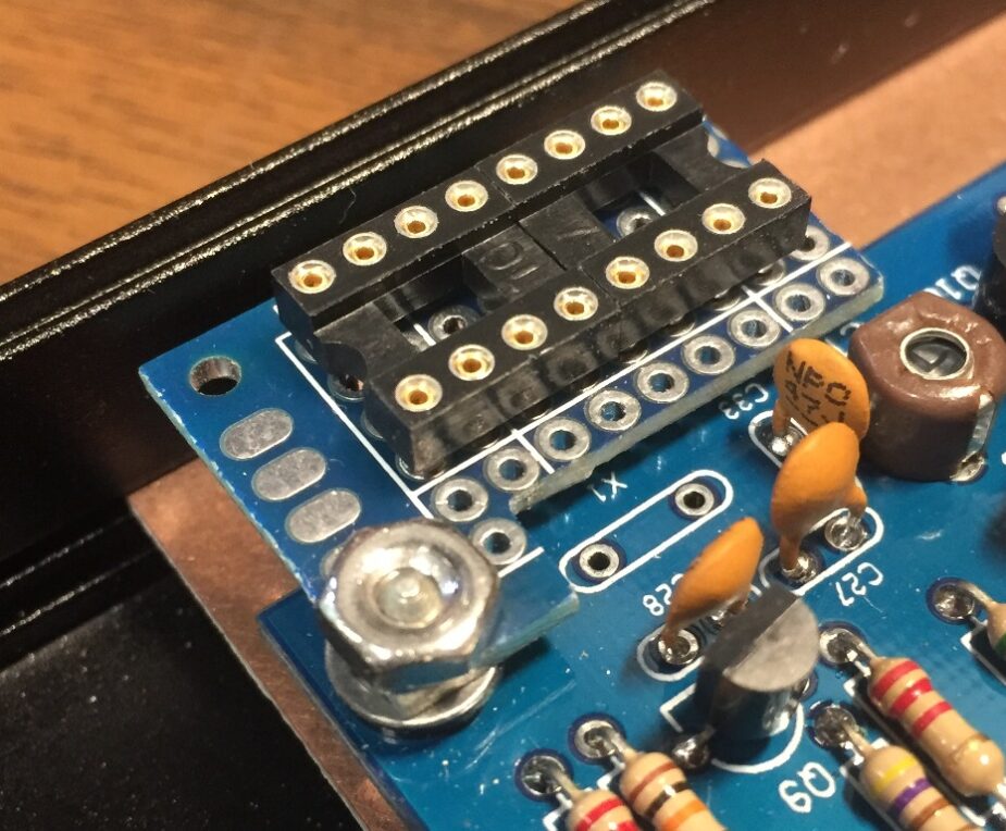
Two small pieces of coaxial cables are used to connect the new PCB to the pads of the ceramic filter, that has been now removed from the original PCB of the receiver. Ground these cables on both ends.
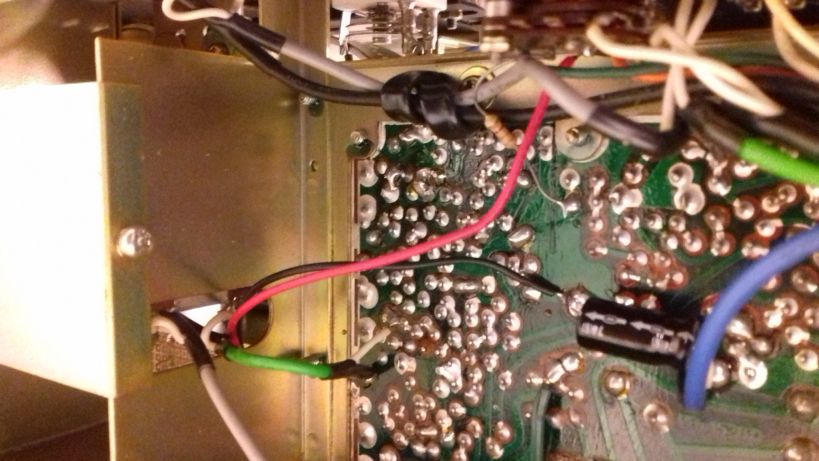
The power cables for the relay coil (shown with red and black in the picture above), are passed below the PCB to the chassis opening and through a hole to the bottom of the original PCB of the receiver. The ground wire is soldered to the filter ground point and the red wire is soldered to the mode selector switch S3d. S3d is the outer wafer onto the switch. Use a multimeter to find the contact of the switch that has VCC when the mode is switched to USB or LSB. This is the point where you want to connect the red wire.
After installing everything, you should perform an alignment of the TC404 and the T406 in the BFO section as described in the manual. This requires a frequency counter, but I did my alignment by simply adjusting the two controls by ear, until I got roughly the same pitch on LSB and SSB audio bandpass. These controls interact, so you have to do a bit of back and forth in both of them. It is very easy.
After installing the modification and aligning the receiver, the result is pretty obvious. No more DSB reception, SSB signals are received just once in the dial and their bandwidth is limited as it should on SSB. The mechanical filter I had, was a bit narrow (2.1KHz) so I can also hear a bit os “seashell” sound on SSB, but SSB voice signals are perfectly understood. It is interesting that the audio volume between the ceramic filter and the mechanical filter was just about the same, which indicates that there is no additional loss in the newly installed filter. Another interesting thing is that there was no need for any impedance matching using active devices or transformers on the mechanical filter. It worked just by directly connecting it. Neither it’s loss, not it’s response seems to be affected by any possible impedance mismatches.
Note that Collins produced both symmetrical and asymmetrical mechanical filters (yes they used two filters, one for USB and one for SSB in some of their gear). My filter is a symmetrical one (same roll-off response curve on both sides of the filter passband). If you use an asymmetrical filter, expect a bit different pitch when switching from LSB to USB and vice versa. Not a huge problem, but just a note.
By performing this simple modification, you will end up with an FRG-7 receiver that is trully selective, allowing for real SSB reception. Most importantly you do not ruin the appearance of your precious FRG-7, but just improving it’s performance. This modification would probably be appreciated much when deciding to sell your FRG-7 to someone else.
Thank you for sharing this practical and affordable project with us, Kostas!
Post Readers: Check out this project and numerous others on Kostas’ excellent website.