One year ago, I posted an article about making the most of social distancing as the world started locking down due to the rapid spread of Covid-19. Here in March 2021, the news is looking much better: vaccines are being distributed at a record pace across the globe and number of cases and deaths are mostly on the decline.
Looking back
As I look back at the Social DX Bucket List I made last year, I’m happy to see that I actually accomplished about 64% of the goals I listed. I knew some of those goals would take well over a year to achieve (the QRP EME one especially).
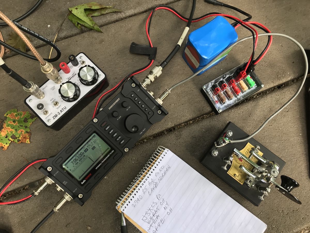
In particular, I’m chuffed that I braved up and started doing Parks On the Air (POTA) and Summits On The Air (SOTA) activations in CW (Morse Code). That was a huge step for me and I’ll freely admit: I was nervous about it. But in July 2020, I managed to do my first CW activation and since then it has become my choice mode of operating in the field. CW is such a simple mode and so efficient–plus it gives me a sense of connection with the roots of radio communications.
I also accomplished a few things I never set out to do:
Not a typical radio year for me
 In a “normal” year, I do way more SWLing than I do ham radio activity.
Last year, I started doing caregiving for my parents in my hometown–I’m typically there 2-3 days a week. While I’ve done shortwave listening and even a little MW DXing in my hometown, I typically don’t have a lot of time, especially in the evening hours. I just want to hit the sack early. QRM is also debilitating there and while I’d like to install a permanent Loop On Ground antenna to mitigate the noise (you heard that right, Andrea!) I’m not entirely sure I’d even have the dedicated listening time to justify it. When I’m there, I like to spend quality time with my folks.
In general, I’ve had much less free time. Indeed, if you’ve written to me via email, you’ll know this based on how long it’s taken me to reply. It can take several weeks especially if the reply requires a detailed response (which many do).
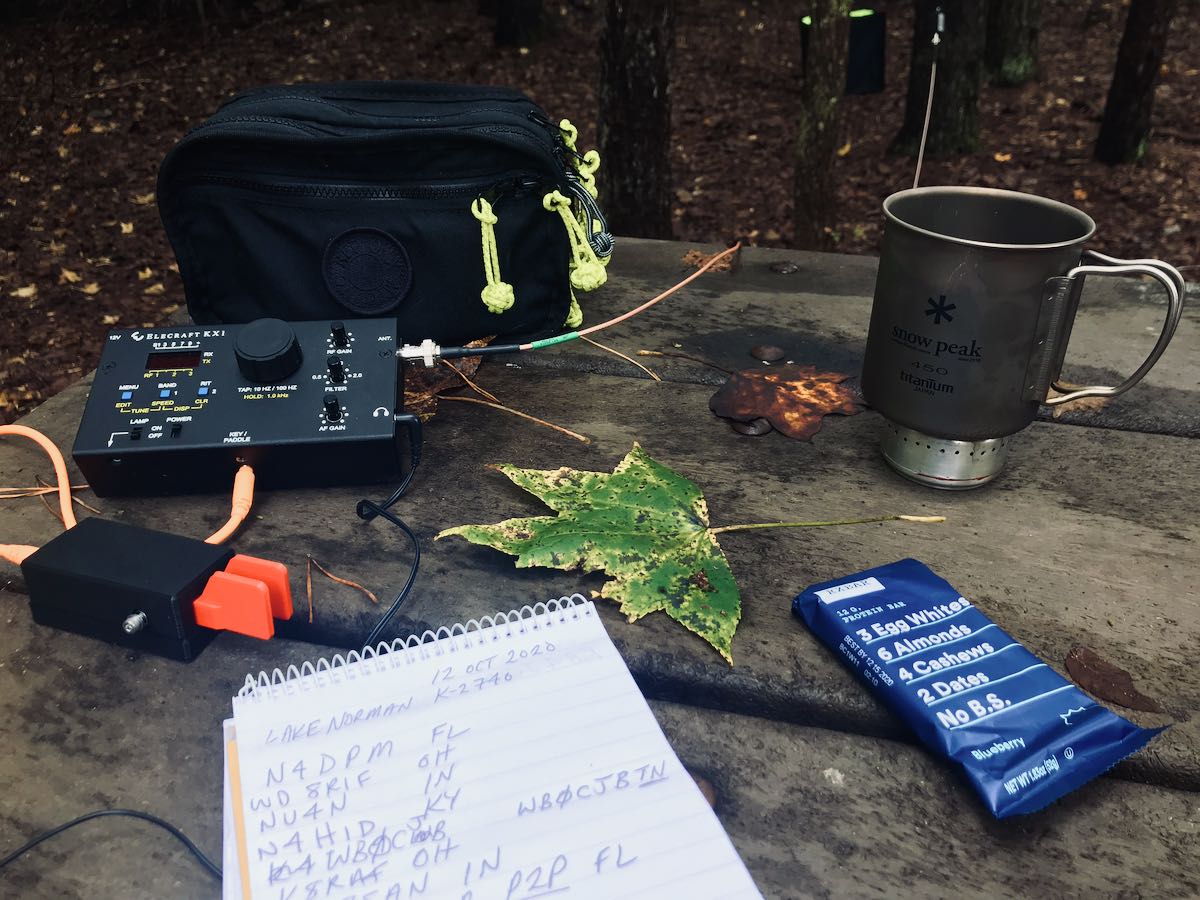
En route to, and on the way back from my hometown, I’ve found that doing park and summit activations has been very rewarding. Last year, I believe I completed a total of 82 park activations.
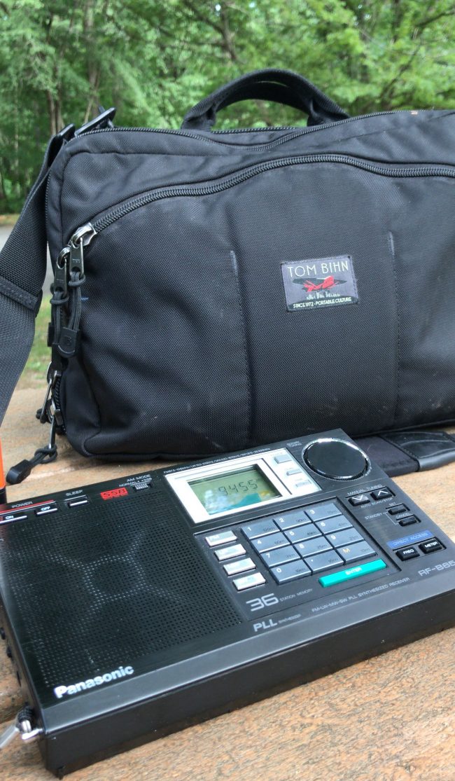
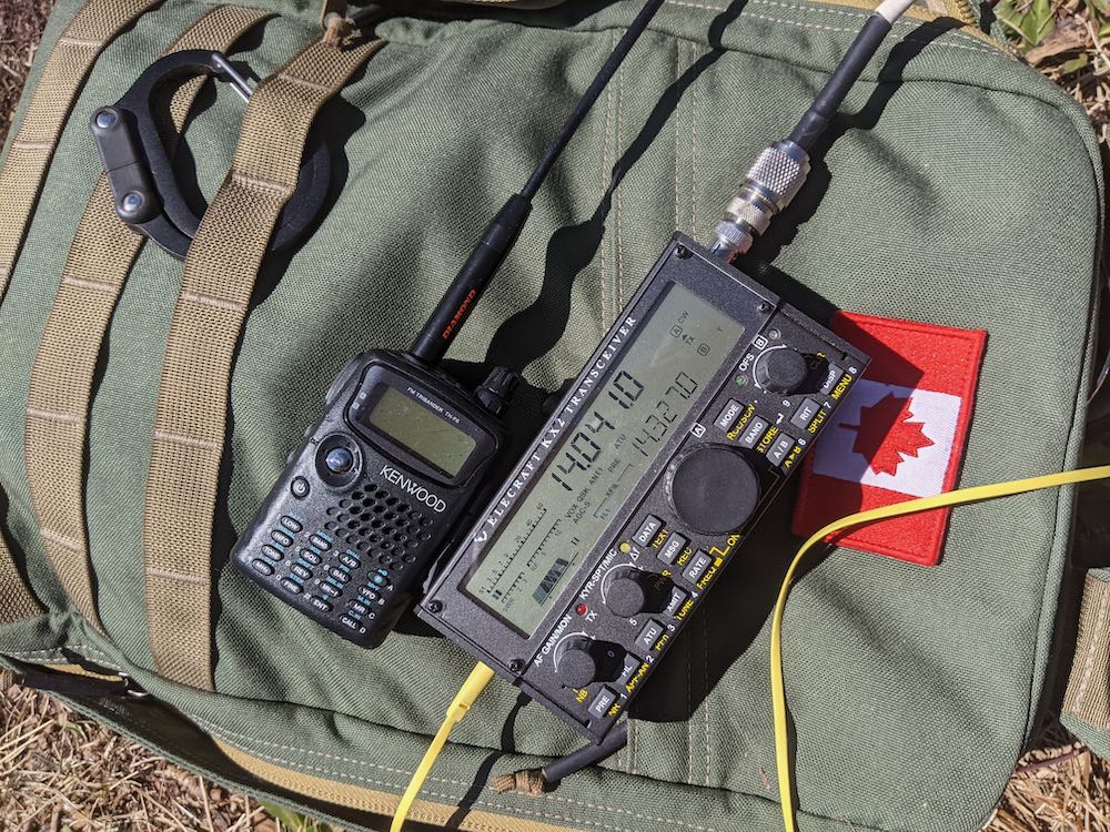
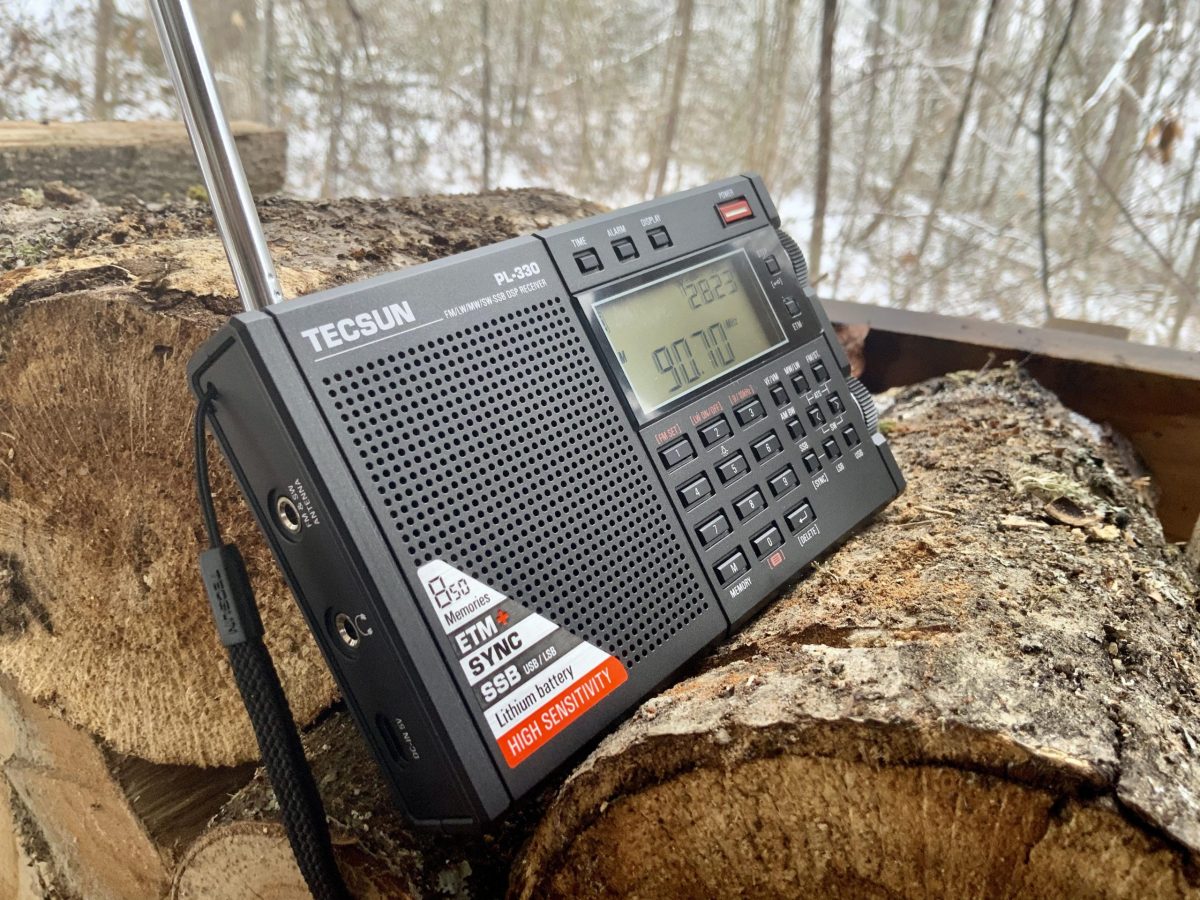
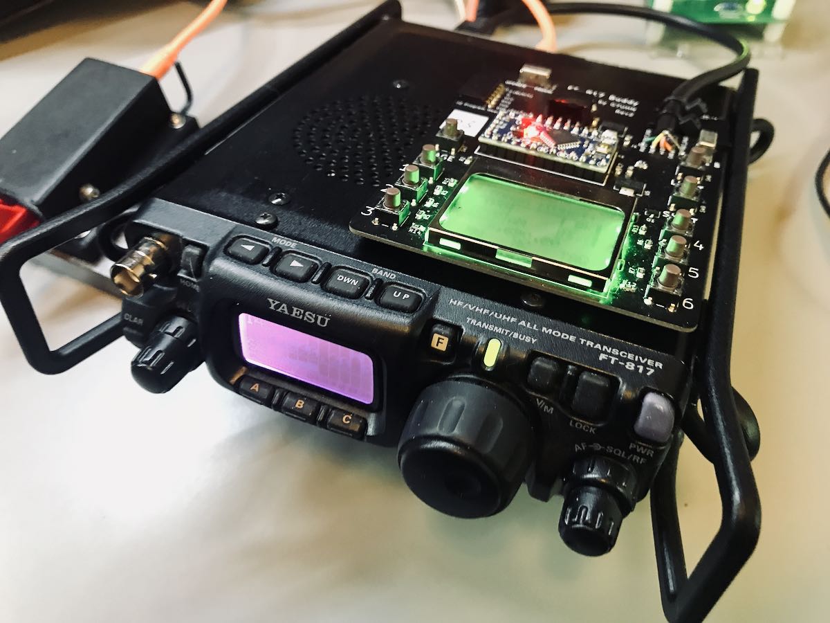
POTA has given me an excuse to explore public lands I’ve never visited before. Plus, I love nothing more than taking radios to the field–both receivers and transceivers.
Hamming and SWLing
At the end of the day, I’m an SWL and a ham radio operator. I find the two activities complimentary.
Side note: As I mentioned in my Winter SWL Fest presentation this year, it saddens me when I receive angry emails from readers after I post items that are ham radio related. We’ve upwards of 7,000-10,000 daily readers on the SWLing Post and the number of complaints are a teeny, tiny fraction of our readership. I only receive messages like this about once a month and they typically say something akin to “I don’t like the ham radio stuff, so if you don’t stop posting it, I’m leaving!” (FYI: That’s a real quote taken from the last one I received in January). I can only assume that at some point in the past, a ham radio operator has been a jerk to this and other radio enthusiasts. It’s a shame, too. I hate seeing the negative impact of one loud troll compared with the encouragement and support of much better people. All of my ham radio friends are not only supportive of SWLing, but almost all got their start in radio via the shortwaves. I’m certainly a case in point.
I love all things radio and I believe the SWLing Post is a reflection of that. If it offends you, then it might make sense to surf somewhere else.
Now where was I? Oh yeah…
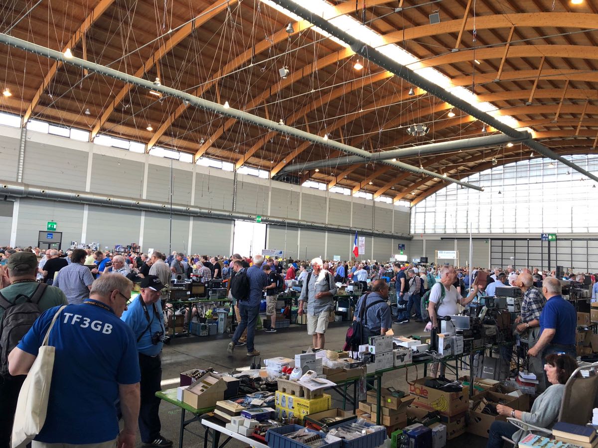
POTA and SOTA outings have helped to satisfy some of my travel cravings as well. I miss going to radio conventions, hamfests, and especially traveling internationally with my family. We are a family who love national parks, forests, and other wildlife areas. Having an excuse to explore public lands we haven’t visited before has been amazing fun.
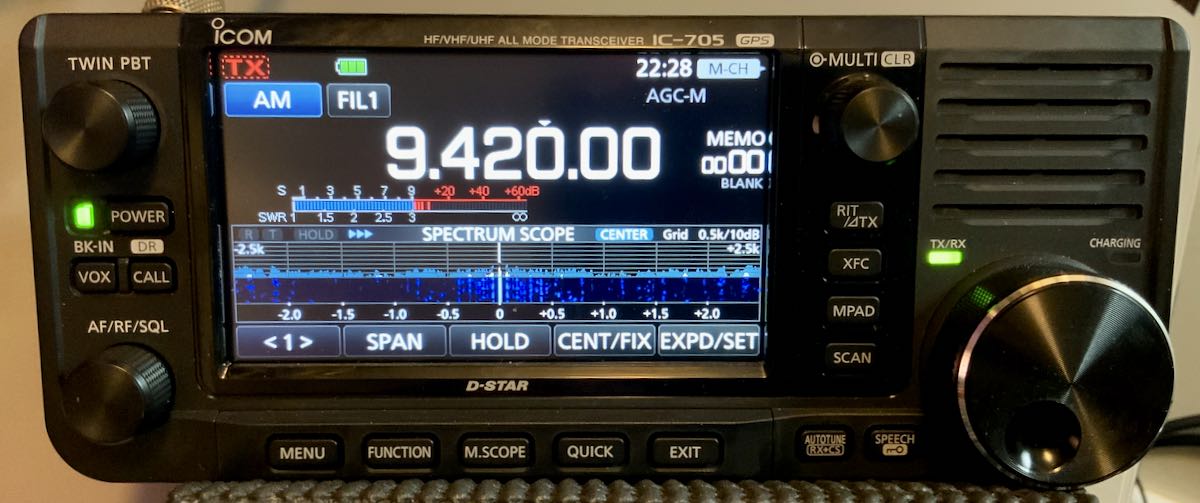
After POTA activations, I’ll often do a little SWLing since I already have an external antenna up and it’s typically connected to a good general coverage transceiver in a spot with zero RFI or QRM. I’ve especially enjoyed my DXing sessions with the superb Icom IC-705.
Listening habits
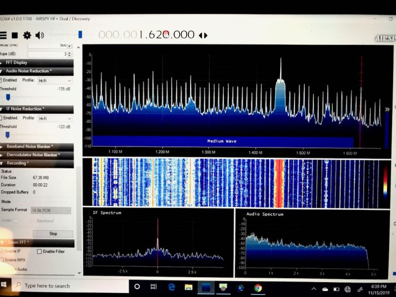 One indicator that I did less radio listening last year was the low number of recordings I made. I checked my audio folder recently and saw that I only made a couple dozen recordings–most were staple broadcasters, not rare or special DX.
At the end of the day, I realize that when I do SWLing sessions I like to have dedicated time–at least an hour or two–with headphones on, losing myself on the radio dial. I simply haven’t had many opportunities this past year to make that a reality.
That’s okay, though. The great thing about the shortwaves is that they’re always there, patiently waiting for us to dive back in!
Looking forward
I’m really not sure what’s in store for me this year, but I know it’ll involve a lot of radio time and that pleases me to no end. I’ve made a few fun goals, but my hope is that, by the end of the year, I may even be able to do some proper travel–maybe even take a flight!
I do know this: I have an even more profound appreciation for my radio enthusiasm as I realize it’s the perfect space to travel and explore the world no matter how “locked down” things are. Based on feedback from readers and contributors to this site, I know I’m not the only one who feels this way.
How about you?
Did your radio activity change or pivot this past year? Did you have more or less time to hit the airwaves? Please comment!