Shortwave listening and everything radio including reviews, broadcasting, ham radio, field operation, DXing, maker kits, travel, emergency gear, events, and more
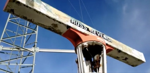
Caroline North is back this weekend live from the MV Ross Revenge on the River Blackwater Estuary near Bradwell, Essex.
Relayed on 1368 kHz with a transmitter power of 20kw from the Isle of Man.
According to Manx Radio’s website as well as being heard in the Isle of Man, the AM service is also audible in Southern Scotland, in the North West, in North Wales and in the West of Ireland and Northern Ireland.
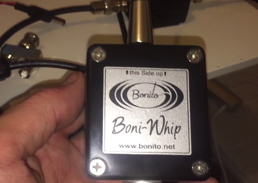
Hi there, if like me, you live in an urban environment, chances are QRM is having a negative impact on the quality of the signals you’re receiving at home. The presence of electrical noise makes antenna choice very important, particuarly if you’re planning to spend more than a few £££s on something more sophisticated than a length of wire. Recently I was considering the the purchase of a second compact antenna, for use at home in my shack and out and about on DXpeditions. I already had the excellent Wellbrook ALA1530 H field antenna, but at more than £250, it’s very costly and thus it seemed rather extravagent to buy a second one, if I could find something with similar performance for less expense. Space is at a premium at home and of course I take much of my equipment out on DXpeditions, so the Bonito Boni whip active antenna appeared to be an ideal choice. A wideband active antenna (from 20 kHz to 300 MHz) operating from 12 to 15V DC, with a very compact form-factor definitely ticked all the boxes. Furthermore, with reasonable second and third order intercept points of +55 and +32.5 dBm respectively, the Boni whip, on paper at least, looked like a pretty good buy at around £100.
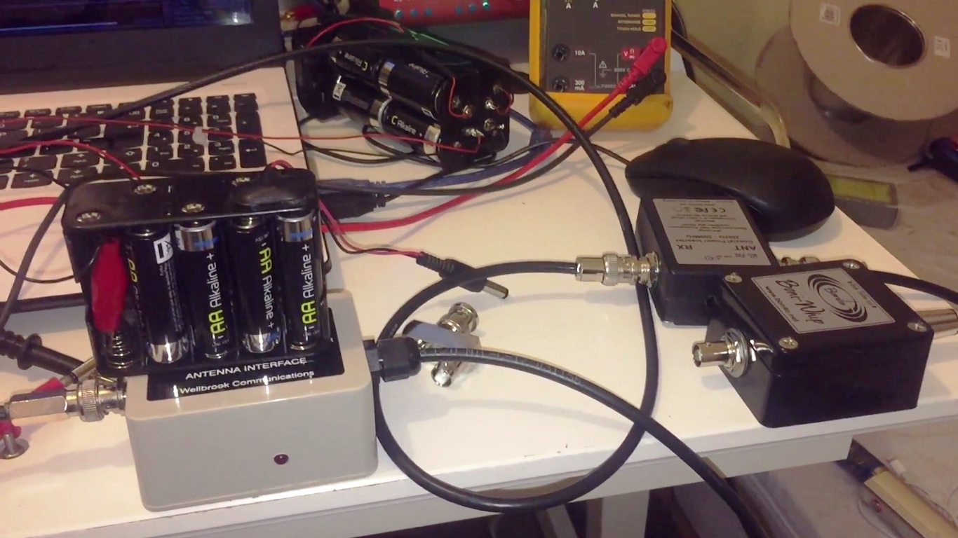
Now, clearly, an E field antenna such as the Boni whip is not going to match the SNR provided by the H field Wellbrook ALA1530 in a noisy, urban environment. I have uploaded a few reception videos to my YouTube channel to demonstrate this, making a direct comparison of the two. However, what about the performance of the whip versus a simple longwire in an urban environment? Is there a delta in performance? The value proposition of the whip is primarliy in it’s performance, coupled with portability I suppose, but that must be considered a secondary requirement. The whip might be 10 or 15 times more expensive than a reel of cheap equipment wire, but will the reception justify the cost delta?!
Text links follow directly below, with embedded videos thereafter; you will find 3 reception videos comparing the whip and a 30 metre longwire, on shortwave and one each for LW and MW. At the end of each video there’s a section with the Wellbrook loop, just to calibrate where the longwire and whip are in terms of a much more effective H field antenna. The result? Well, there’s not much to separate the longwire and Boni whip, except on LW, where the whip prevails. A friend told me recently, if reception is rubbish at home under a blanket of QRM, don’t blame the antenna, the noise is the real problem. He was right. So, the next tests are to be undertaken out in the field, where the whip has a real chance to shine. I’m rooting for it because to have an antenna that performs as well as, or close to my loop out in the woods, yet can be packed away into a small case would be brilliant. Thanks for reading/watching/listening.
Clint Gouveia is the author of this post and a regular contributor to the SWLing Post. Clint actively publishes videos of his shortwave radio excursions on his YouTube channel: Oxford Shortwave Log. Clint is based in Oxfordshire, England.
Many thanks to SWLing Post contributor, William Lee, who shares the following story from the CBC:
Hello, Finland, this is Vancouver calling: radio fans listen to CBC from 6,700 km away
When people in other parts of the world tune in to CBC Radio in Vancouver, they usually do it through our app, or online or through Sirius XM.
But some people in Finland recently picked up Vancouver’s CBC broadcast — the broadcast heard locally at 690 AM and 88.1 FM — using an elaborate antenna system roughly 300 kilometres north of the Arctic Circle in Lapland, Finland.
“It’s a few [radio hobbyists] from around Finland who have a very nice place up in the north where there’s not much neighbours which means not much interference,” Patrik Willfor, one of the listeners, told On The Coast host Stephen Quinn. “It’s like a silent band there, so even the weakest signals come through.”
The practice is called DXing, and Willfor says he’s been at it for about 25 years since a friend told him that’s what their fathers used to do when they were young.[…]
Post readers: Is it just me? Or do you, too, get a kick out of it when the press gets a glimpse into the seemingly-anachronistic, but still-relevant-and-rocking world of radio–?
Note that you can also listen to the audio interview with Patrik via the embedded CBC player below:
Is the irony of this really lost on the ABC management? Replace shortwave radio (~$20) with a sat phone (~$700+subscription) @Malarndirri19https://t.co/kzWRDbvQ7d
Many thanks to SWLing Post contributor, Chris Kadlec, who shares the following announcement about his Seoul AM Radio Listening Guide:
After a long 14 months of work, I’m happy to present the completed Seoul AM Radio Listening Guide, a three-hour documentary broadcast exploring the Seoul AM band one frequency at a time, plus a look at the radio war on the Korean peninsula accompanied by a 115-page guide.
In addition to radio broadcasts from across East Asia, the broadcast includes Korean noise jammers and AM, FM, shortwave, and television propaganda broadcasts from both the north and the south, additionally outlined in a 25-page broadcast transcript and 115-page informational guide. It also includes:
* A comprehensive list of 260 East Asian AM stations, including station names, tower locations, distance and direction from Seoul, parallel FM frequencies, broadcast hours, and station website links.
* A full bandscan of 235 regular nightly skywave signals as heard after the sun sets over Seoul.
* Daytime groundwave bandscans taken from eleven different locations in the Seoul metro area, along the North Korean border, beside the sea, and in Korea’s mountainous interior with background information about each location.
* A guide showing stations organized by their network affiliations in addition to privately-owned stations and networks. Alternatively, stations are also shown organized by country, region, and city.
* A chart showing signal strength for each bandscan – day and night – in bar graph format.
* A full colour-coded regional station map covering both skywave and groundwave signals.
* A view of some of Korea’s signal jammers as seen on an SDR (software-defined radio).
* Plus, a complete transcript of the three-hour audio broadcast with additional information on the featured audio clips as well as the songs featured in those clips.
– Chris Kadlec
Brilliant, Chris! I can only imagine the amount of time and effort you’ve put into this guide. Thank you!
Some inhabitants of French controlled Polynesia are unhappy at the switch over from Medium Wave AM to VHF FM broadcasting
Radio New Zealand reports Radio Polynesie Premiere switched to an all FM service at the beginning of December, leaving pockets of inhabitants in valleys and on remote atolls without any local radio service.
The broadcaster added five FM transmitters to its network of 48 to improve its reach but in an area the size of Europe, the signal fails to reach all communities.
Concern has been expressed that vital weather warnings are no longer heard.
The mayor of Makatea in the Tuamotus Julien Mai said there is a risk to public safety because people have always been advised to have an emergency kit that includes a radio when severe weather strikes.
On Christmas Eve morning, the electricity went off at our house and panic quickly spread among our younger guests.
First, the TV sets went dark. Then, the desktop computers began to die as UPS back up batteries failed. For a while, we were reassured by the sound of familiar alarms, but then suddenly, total silence. Could this be the end times? Is this the onslaught of the apocalypse?
Smart phones were quickly deployed and guests began calling each other from room to room. The panic began to subside when several millennials volunteered communal usage of their wireless data plans. The kingdom would be saved…crisis abated.
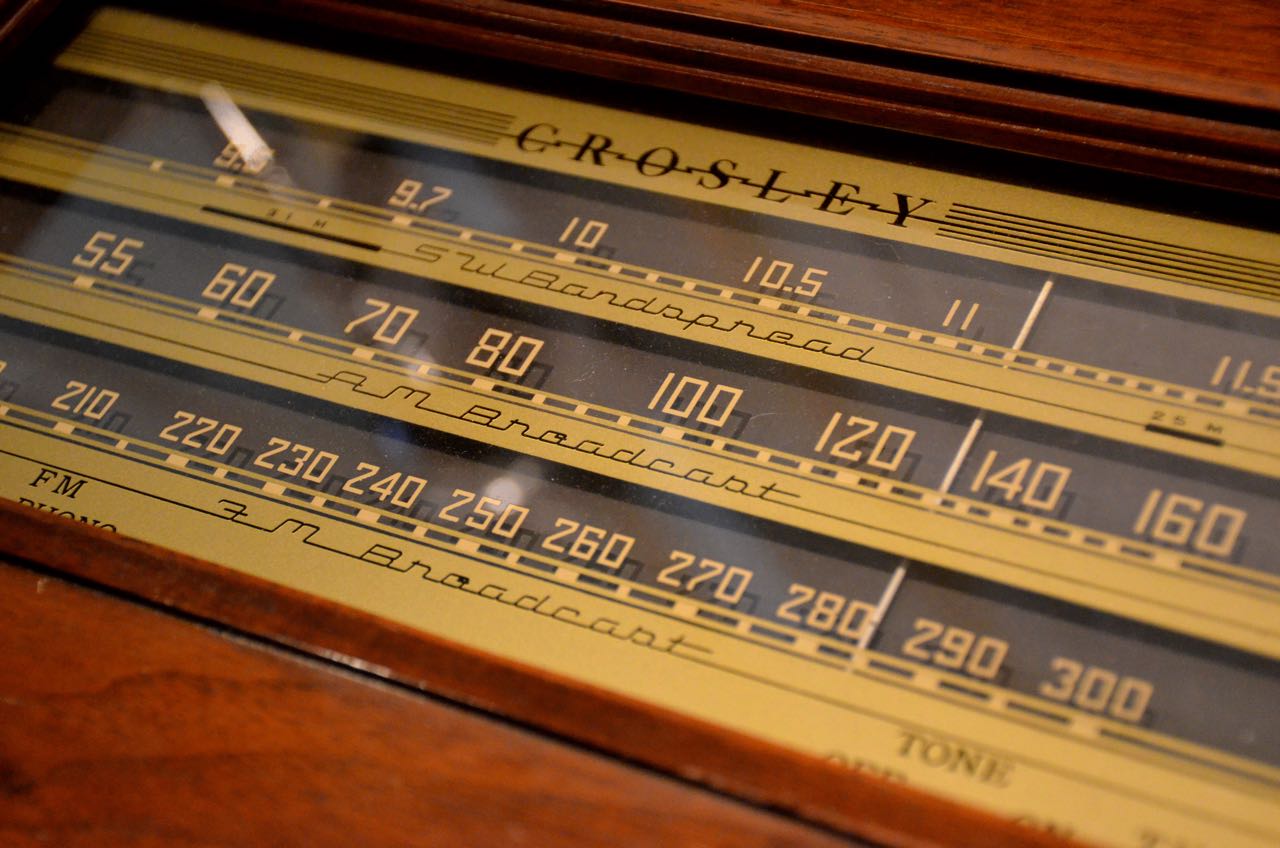
[…]As the younger generation huddled around the smart phones with data plans, I began to think of the outage as an opportunity to listen to AM Radio, so I went to my office and dusted off my old RCA SuperRadio III.
I couldn’t remember the last time I replaced the batteries but to my surprise, it came to life with its signature popcorn sound when I pushed its big silver button. “IT’S ALIVE” WOW…the AM band was extraordinarily quiet and responsive.
[…]I scanned across the dial from 610 AM to 1590 AM. All the stations were as clear as a bell. Then, I decided to press my luck. I tuned to KTSA 550 AM in San Antonio and then I moved the dial slightly to the right and heard KLVI 560 AM in Beaumont, Texas. Every station was booming in loud and clear.
I felt like a child with a new toy. I dialed up and down the band, experiencing the clear booming sound of AM Radio without any noise or interference. It was a feast for the senses. It was beautiful.
After a few minutes, one of my daughters walked in and asked about the source of my entertainment. I pointed to my SuperRadio and said joyfully, “listen”. She looked at the big black box and asked “How can you listen with the internet and electricity off?” I responded, “It’s my portable SuperRadio III.” Before I could explain further, she shrugged her shoulders, closed the door and went back upstairs, convinced that her Dad was conducting some sort of high tech experiment.
In a manner of speaking, her assumption was correct. I was listening to AM Radio in a big city without the interference of computers, wireless modems and an overloaded electrical grid. For the first time in my recent memory, the “Senior Radio Band” sounded beautiful. Sadly, my experiment ended with preordained results when the electric power was restored.[…]

 (Source: Mike Terry via Southgate ARC)