Category Archives: Radio Modifications

Modification to make the XHDATA D-220 dial easier to read

Many thanks to SWLing Post contributor, Jason Harvey, who writes:

Just thought I’d share, I’ve seen the bandaid dial scale mod for the D-220 to help with tuning. Not sure if anyone else has been able to mod the actual dial marker yet to make it more visible on the orange D-220 though, but it’s really not hard if you’re used to working on electronics. I just pulled the 2” plastic dial “string” out of mine after removing the back and lifting the circuit board, painted the front tab black, and reinstalled it in reverse. The end of the “string” has a tiny tab that just plugs into the front of the tuning pot cover, and when reseating the board it all slips back into place with a little guidance. This is made easier if you leave the tuning pot in the same spot it’s in when you lift the board, which one should note when they start.

[…] I came across this video that describes modding the XHDATA D-220 dial for better visibility.

Spread the radio love

Comparing the Watkins-Johnson WJ-8711 & WJ-8712 with TEN-TEC RX-340 & RX-331 receivers

Many thanks to SWLing Post contributor, Paolo Viappiani, who shares the following guest post:


The WJ-8711 & WJ-8712 vs. Ten-Tec RX-340 & RX-331 Receivers

by Paolo Viappiani, Carrara, Italy

In recent years, a renewed interest has grown in regards to the best HF receivers using “first generation” DSPs, typically the HF-1000/HF-1000A, WJ-8711/WJ-8711A and WJ-8712 models by Watkins-Johnson and the RX-340 and RX-331 models by Ten-Tec. Even today, the aforementioned receivers are considered among the best performers of all times; this is a well-deserved fame in the case of the W-Js, a bit less with regard to the units manufactured by Ten-Tec, a firm that once had a good reputation but that has been recently acquired by a new owner (who sold the old facilities by transferring the company and distorting the sales, support and assistance policies of the previous company [2]). I therefore believe that this article serves as a dutiful information for the readers who are potentially interested in these receivers.

A Bit of History

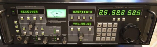
In the years between the last and the present century, two receivers very similar to each other in terms of design and structure were released almost simultaneously by Watkins-Johnson of Gaithersburg, Maryland [1] and by Ten-Tec of Sevierville, Tennessee [2]: the WJ-8711 (later upgraded to the A and A-3 versions and followed for a short period by the HF1000 and the  HF1000A  “civilian” versions [3]) and the Ten-Tec RX-340; both of them are shown in Figure 1.

Figure 1: The WJ-8711A (above) and Ten-Tec RX-340 (below). Notice the similarity of the front panels of the two radios.

The WJ-8712/WJ-8712A and the Ten-Tec RX-331 receivers were released by their respective manufacturers in that period also (the latter one was preceded by the RX-320 and RX-330 models). All these types were nothing more than “black-box” units, that in all respects corresponded to the WJ-8711A and to the Ten-Tec RX-340 receivers but that had not been provided with true front panels, as they were controlled by special hardware interfaces or from a PC, look at Figures 2 and 3.

Looking at the appearance of the WJ-8711/HF1000 receiver series and of the Ten-Tec RX-340 units, a relative similarity to each other is evident, and it has led to various speculations regarding the design of both devices.

One of the theories was revealed by James (Jim) C. Garland W8ZR of Santa Fe, New Mexico [4], about which he claims to have obtained information from a Ten-Tec employee directly. James claims that in 1991 the US Government Agency NSA (National Security Agency), which used to purchase numerous HF receivers for surveillance and interception, decided that the current cost of the receivers were too high and formed a special group in order to study how to obtain a possible price reduction.

At that time the high-end HF receiver market was dominated by a few manufacturers: Watkins-Johnson, Racal, Cubic, Rockwell-Collins and a few others, and Ten-Tec applied for joining the group.

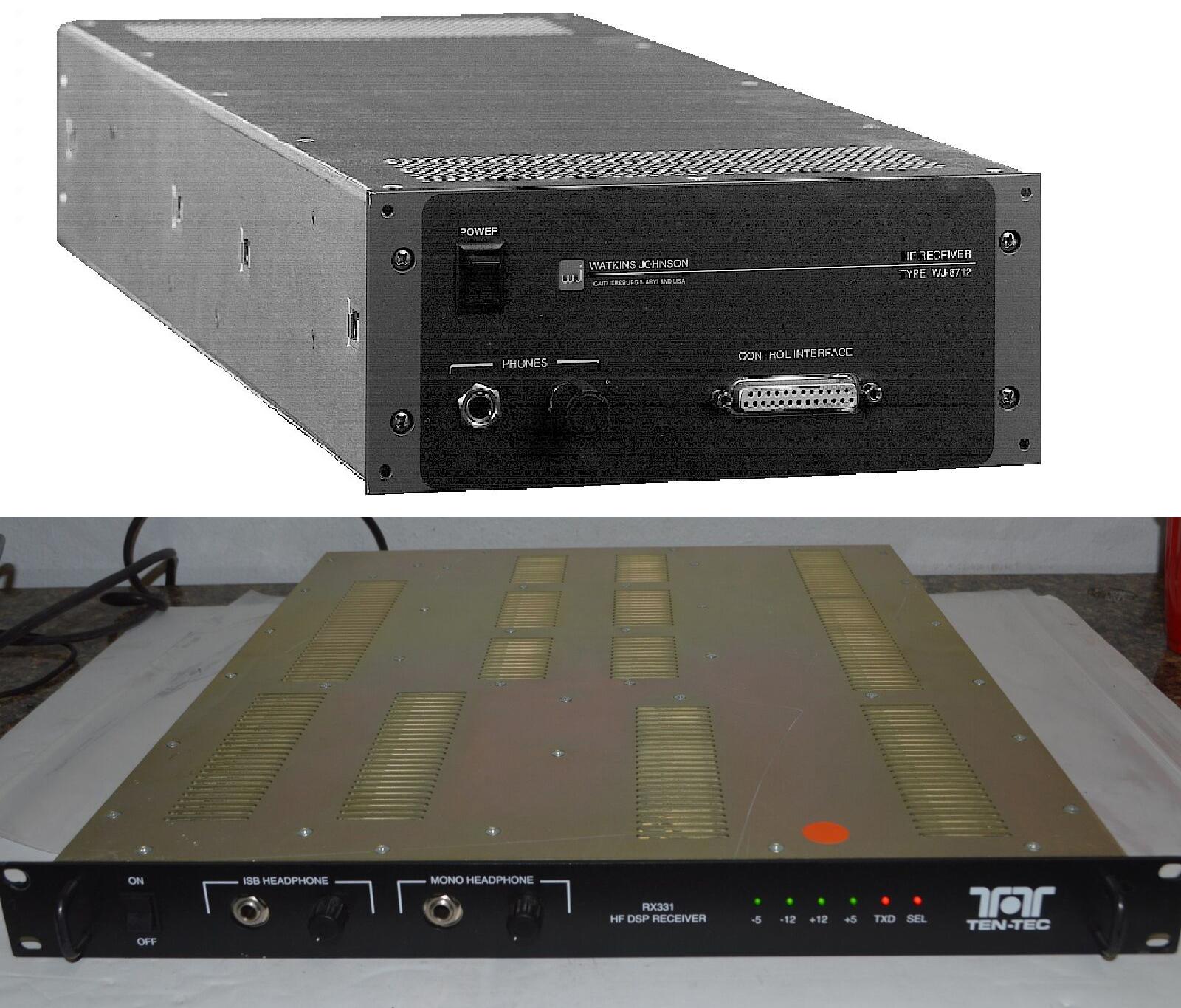
Figure 2: The WJ-8712A (above) and Ten-Tec RX-331 (below). While the Watkins-Johnson model is two rack units high and half wide, the Ten-Tec develops less in height (only one rack unit) and more in width (standard 19” rack). However, both receivers are quite deep (more than 20”-50 cm.).

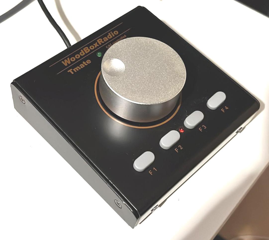
Figure 3: The Tmate unit of the WoodBoxRadio is shown here; it is one of the possible accessories which, together with a PC monitor, allow using the “black-box” receivers via an RS-232 interface.

According to the information provided by Jim Garland, the Watkins-Johnson and the Ten-Tec designers worked together for about one year in order to agree on the technical characteristics and guidelines of the “radio of the future” which must meet all the requirements that the NSA requested.

Continue reading

Spread the radio love

Kostas pairs his Collins 51S-1 with a Heathkit SB-620 bandscope

Many thanks to SWLing Post contributor, Kostas (SV3ORA), for sharing the following guest post which originally appeared on his radio website:


Collins 51S-1 band scope using a Heathkit SB-620

by Kostas (SV3ORA)

The purpose of this project, is to connect a Collins 51S-1 receiver with a Heathkit SB-620 “scanalyzer”, so as to give the 51S-1 band scope capability. Right into the schematic presented below, a slight modification is needed to the 51S-1. I usually do not do modifications to old equipment unless absolutely needed and even when I do so, I take care for them to be easily undone and to modify them as little as possible.

The modification to the 51S-1 is simply a small coupling capacitor connected to the plate of the mixer tube V4A and a short run of thin coaxial cable, connected as shown, to one of the several SPARE RCA connectors at the back of the 51S-1. Collins engineers were smart enough to include SPARE RCA connectors at the back of the radio, which are not connected to anything inside the radio circuit, to be used for different future purposes. So we do not have to drill any holes to the chassis of the precious receiver, which would be catastrophic.


Click to enlarge.

The coupling capacitor is just 5pF, so compared to C125, this presents only a tiny fraction of the loading to V4A plate, i.e. not affecting the normal operation of the receiver. Note, you cannot take directly the 500KHz IF output that is originally provided by the 51S-1 RCA in the back of the radio. This is because this IF is AFTER the filters, so it is a narrow IF. We need WIDE IF for the scanalizer to work properly, so you have to perform this tiny modification to the 51S-1.

No need to say that the SB-620 needs to be re-tuned for 500KHz instead of 455KHz. I was unlucky and my SB-620 did not have the appropriate L3 to be tuned to the IF of 455/500KHz. Mine had the L3 used for an IF of 5.2-6MHz. I converted the SB-620 to work down to 500KHz by using this original higher-frequency L3 and adding two additional inductors to it, one at its bottom and one at its top, so as to make L3 larger. The additional bottom inductor I added (connected from the bottom of L3 to the ground) was a 15uH choke. The additional top inductor I added (connected from the top of L3 to C3 and C5), was a 455KHz IF CAN transformer (the one with the adjustable yellow-painted cap) taken out of a transistor radio. Of course I have removed the internal capacitor of the transformer before using it. My transformer had something like 200-300uH in the mid-set point. It is not too critical as this is a tunable transformer.

By making this modification to the SB-620 you can bring the 5.2-6MHz L3, down to 500KHz. Of course the slug of L3 now has limited tuning range. But we can coarse tune the hybrid L3 now, by tuning the IF transformer that has been added. This solution worked like a charm and the original L3 is still fit in place, looking original and helps in fine tuning if needed. For the optional mixer input (points A, B, C on the SB-620), I used circuit #1, but I did not notice any real difference from circuit #3. RFC1 is 304uH and I connected three 100uH chokes in series to make this RFC.
The solution described in this page, will add a huge value to your vintage receiving station. SWLing feels just different by having an all-tubes computer-free band scope. Here is a picture of the setup, nicely glowing in the night. That P7 CRT blue phosphor with its green afterglow “memory” effect looks amazing! Narrow resolution is actually only achievable, because of this afterglow of the CRT, which allows for much slower sweep rates.

Spread the radio love

Pavel fixes a stereo lock in the Eton E1

Many thanks to SWLing Post contributor, Pavel Kraus, who shares the following guest post:


Eton E1 – fault in stereo reception

I recently became the owner of an Eton E1 receiver, which I obtained on eBay from the USA.

The receiver is great, everything worked, error-free display. The only problem was that even FM and strong local stations did not play stereo even though stereo reception was set in the menu. The stereo text on the display flashed several times when the stations were not tuned in precisely, but after the stereo tuned, the text went out. I know that stereo reception is not the most important thing for this receiver, but it bothered me that there was a defect at all.

The Sanyo 3335 stereo decoder is used in this radio. The stereo reception switching threshold can be set with a 10kohm potentiometer which is connected to terminal 4 of the integrated circuit:

I disassembled the radio by loosening the screws on the back of the radio. The receiver is divided into two parts. I removed the XM module and disconnected the part of the radio with the display from the flat wires on the second printed circuit board of the radio

I then removed the screws on the circuit board located at the back of the radio.

I removed the printed circuit board and found a matching resistor trimmer on the other side of the circuit.

Then I connected these two points with a wire (when running on batteries) so that I could turn on the receiver:

After tuning in to a strong local transmitter, I carefully turned the trimmer until the stereo sign lit up and listening to the headphones made sure the sound matched the stereo. I repeated this at several local stations.

The receiver now plays stereo perfectly and the settings do not affect other parameters of the receiver. After assembling the radio, I was able to enjoy quality stereo reception.

Spread the radio love

Guest Post: “Tinkering with History”

Many thanks to SWLing Post contributor, Bob Colegrove, who shares the following guest post:


Tinkering with History

By Bob Colegrove

One of the attractive aspects of radio as a hobby is that it has so many specialties to channel our time.  Just for the sake of classification, I would group these into two categories, listening and tinkering.  I think the meaning of each category is fairly intuitive.  Probably few of us approach our interest in radio in the same way.  Most of us have dabbled in more than one listening or tinkering specialty.  Perhaps we have been drawn to one particular area of interest, or we may have bounced around from one to another over a period of time.  I know the latter has been my case.

Tinkering might start with a simple curiosity about what makes the radio play, or hum, or buzz, and progress to an obsessive, compulsive disorder in making it play, hum or buzz better.  Unfortunately, over the past 30 years or so, the use of proprietary integrated circuits, as well as robotically-installed, surface-mounted components have greatly short-circuited what the average radio tinker can do.  For example, I have noticed a lot more interest in antennas over that period, and I think the reason is simple.  The antenna is one remaining area where a committed tinker can still cobble up a length of wire and supporting structure and draw some satisfaction.  But the complexity and lack of adequate documentation have largely kept newer radio cabinets intact and soldering irons cold.  Bill Halligan knew you were going to tinker with his radios, so he told you how they were put together.  The fun began when you took your radio out of warranty.  If you did get in over your head, there was usually somebody’s cousin not far away who could help you out.  The following is a sample of how one resolute tinker managed to overcome the problem of locked-down radios in the modern age. Continue reading

Spread the radio love

Radio Mods: Unblocking the YAESU FRG-8800 Frequency Coverage Limitations

Many thanks to SWLing Post contributor, Paolo Viappiani (SWL I1-11437), who shares the following guest post. Note that, as with any radio modification, perform this operation at your own risk. This is a very simple mod, but if you feel it might be beyond your skill level, consider hiring a radio technician to perform it on your behalf:


Unblocking the YAESU FRG-8800 Frequency Coverage Limitations

by Paolo Viappiani

Figure I: An unblocked FRG-8800 receiver tuned to 29.999.9 MHz.

Introduction

It is well known that some receivers produced in the last decades of the last century suffered from a limited frequency coverage due to legislative restrictions in force in some countries (Germany, Australia, etc.).

In particular, in Germany it was forbidden to listen to HF frequencies higher than 26.1 MHz, while in other Countries shortwave were not allowed to receive frequencies below 2 MHz.
These restrictions led most radio manufacturers to produce “blocked” versions of their HF receivers in order to satisfy the various national requirements; almost classical examples are the world renowned SONY ICF-2001D and the PHILIPS D-2935/D-2999 portables.

The blocking/unblocking procedure of some frequency bands was quite simple in microprocessor-governed synthesized radios: usually it was sufficient to add (or remove) proper jumpers in the vicinity of the microprocessor to perform the task, and the correct procedure was often covered in the Service Manuals or in specific Technical Bulletins; in any case plenty of information can be found on the Internet. Continue reading

Spread the radio love

Jerome makes an aluminum back stand for the PL-880

Many thanks to SWLing Post contributor, Jerome van der Linden, who writes:

Hello Thomas,
I have managed to break three of these flimsy PL-880 back stands, and thought, “how hard can it be to make one out of metal?”

These two photos are the result from a piece of aluminium that I had in the shed (yes I know you guys call it aluminum) . Here’s hoping it lasts longer!

I love it, Jerome.  I’m willing to bet your backs tand will outlast the PL-880 now!

Thanks for sharing. I love this simple aluminium (remember, I lived in Europe–ha ha) solution! 🙂

Spread the radio love