Category Archives: Shortwave Radio

Alan Roe’s updated A18 season guide to music on shortwave

Many thanks to SWLing Post contributor, Alan Roe, who notes:

I have now updated my Music on Shortwave listing for A-18, and attach version 2.1.version 2.0.

Alan, thanks so much for keeping this excellent guide updated each broadcast season and for sharing it here with the community!

Click here to download a PDF copy of Alan Roe’s Music on Shortwave A-18 v2.1

Gary pulls apart and examines the XHDATA D-808


Many thanks to SWLing Post contributor, Gary DeBock, who shares the following report of the XHDATA D-808:


XHDATA D-808 AM-LW-FM-SW-AIR Portable- Tech Report

by Gary DeBock

The XHDATA D-808 portable is an AM-LW-FM-SW-SSB-AIR band model which has already been the subject of many excellent reviews. Until recently the model was not marketed to North American purchasers, but recently a couple of Chinese sellers have started soliciting North American buyers via eBay listings.

My own interest in the model was in comparing its AM Band performance to that of the best performing Ultralight radios– specifically the CC Skywave and Skywave SSB models. Although the D-808 is slightly larger than the 20 cubic inch limit for Ultralight radios, its size and weight make it very convenient to take along as a “travel portable,” specifically as an SSB-enhanced model capable of checking transoceanic station carrier strength on exotic ocean beaches. The Skywave SSB model can also do that– but at a $169.99 list price, compared to the $112.86 (plus $10 shipping) cost of the D-808. In addition, none of the published D-808 reviews seemed to have any information about internal components like the loopstick, or Si4735 DSP chip.

My first test was to compare the stock Skywave SSB model with the D-808 in fringe AM station reception. The Skywave SSB model has a reputation of being one of the most sensitive Ultralight radios, but the D-808 clearly outperformed it on both low band fringe station (550-KARI) and high band fringe station (1700-City of Auburn TIS) reception. The D-808 couldn’t quite hang with a 7.5″ loopstick Skywave model, but that only made me curious about how the same modification could enhance the D-808. So… it was time to disassemble the D-808, and find out why its loopstick was such a superior performer.

The D-808’s 3 7/8″ (98mm) loopstick is shown adjacent to the 2 3/4″ (70mm) loopstick of the CC Skywave models. The D-808 is much easier to disassemble than the CC Skywave models, though, so enhanced loopstick transplants should prove to be quite popular in the D-808.

The D-808 loopstick is 3.7/8″ (98mm) long, while that of the CC Skywave SSB model is only 2 3/4″ (70mm) long. Other reviewers have noted the excellent performance of the D-808 on the AM band, and this is probably one of the main reasons. The SSB mode operates very similar to that of the Skywave SSB in providing a quick check of carrier strength on weak AM band targets– the LSB mode can be set to +55, and the radio tuned to different frequencies to check fringe station carrier strength. This can provide a real-time check of propagation changes during time-limited propagation openings for live ocean beach DXing with Ultralight radios or other portables (or with the D-808 itself, if desired).

The D-808’s Si4735 DSP chip was initially used in the Eton Traveler III Ultralight radio model, which was fully reviewed in the 2015 Ultralight Radio Shootout (where it won top honors for MW sensitivity). The D-808 augments that capability with a significantly longer loopstick, plus multiple DSP filtering selections. As such, the D-808 in stock form should be a very superb performer.

The Si4735 DSP chip has markings of “3560, DCUL, .738” and provides a wide range of AM bandwidth choices for the Medium Wave DXer (6K, 4K, 3K, 2.5K, 2K, 1.8K and 1K). These perform very well, and as with the other DSP-enhanced portables, the narrowest bandwidth (1K) provides the most sensitive AM band reception.

In construction very similar to that of the CC Skywave, the D-808 separates into two main circuit boards, connected together by a plug-in ribbon cable. One strange quirk is that the Si4735 DSP chip is located on the RF board (close to the center right edge). The Si4735 DSP chip is also used in the Eton Traveler III Ultralight radio, and although that model lacks the multiple DSP filter selections of the D-808, is has been the subject of highly successful 7.5″ loopstick transplant modifications– proving that such enhanced Medium Wave and Longwave loopsticks will perform very well in the new, Si4735 chip- powered D-808.

Disassembly of the D-808 model is fairly straightforward in comparison to the CC Skywave models, and the technician doesn’t need to memorize a detailed reassembly protocol in order to perform a routine loopstick transplant operation. Neither C.Crane nor XHDATA are likely to show any sympathy to someone botching up an antenna transplant, so you need to be confident that that your skills are superior to those of the company technicians before taking the plunge. In the CC Skywave and CC Skywave SSB models various parts fit together like a puzzle, but the D-808 isn’t like that. It should prove to be a fairly popular model for enhanced MW and LW loopsticks.

Those considering a purchase of the D-808 should be advised that its type 18650 Li-ion 3.7v battery is not commonly available at most stores, and that Postal regulations supposedly forbid shipping these batteries through the mail. One of the eBay sellers (harelan ecommerce) did manage to ship me two of the standard XHDATA type 18650 batteries through the mail (along with two new D-808 models) but if your seller won’t do this, you can still purchase the batteries on eBay. Some of the 18650 batteries sold on eBay have a flat positive terminal which won’t contact the D-808 cabinet’s positive battery connector terminal, but in such a case you can simply insert a #8 lockwasher in between the two, and the arrangement will be very secure. From that point on you can simply recharge the battery with a USB terminal connector.


Thank you for sharing this technical overview of the XHDATA D-808, Gary! I’m looking forward to the antenna mods you’ll no doubt make to this compact DX machine!

Click here to read other posts about the XHDATA D-808 and here to read posts by Gary DeBock.

How to build SM0VPO’s 20 meter magnetic loop antenna

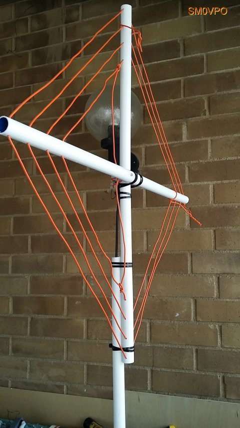
The completed 20 meter loop antenna.

A few days ago, SWLing Post contributor, Robert Gulley (AK3Q), pointed me to an excellent website by Harry Lythall (SM0VPO) which is chock-full of various homebrew radio projects. In particular, we both were impressed with Harry’s 20 Meter Loop Antenna–it’s such a simple project and requires no special order components. In fact, all of the components (save, perhaps, the antenna connector) can be purchased at a DIY store.

I reached out to Harry and he has kindly allowed me to republish this project as a guest post:


20m Loop Antenna

by Harry Lythall – SM0VPO

Introduction

I recently saw that my 80m (3.5MHz) loop (or frame) antenna has been really popular, and that there are loads of other radio amateurs who have taken my design and “ran with it” to produce variations that all have some great improvement. There have been many in-depth tests and simulations, all with exceedingly good results and reports. This is exactly what I am aiming for with my homepages – free information for all and my designs being improved upon. That way we all win 🙂

One small point all variations have in common is the need for an expensive tuning capacitor and a very restricted RF power level. Of course, you can throw money at the problem, but for me this hurts. I got to thinking that there must be a way of adjusting the design a little and finding another technique to tune the antenna, and to make the best use of the little radio transceiver I have in Sweden, given the limited space.

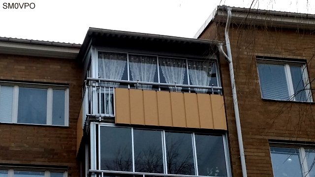
My limited space apartment.

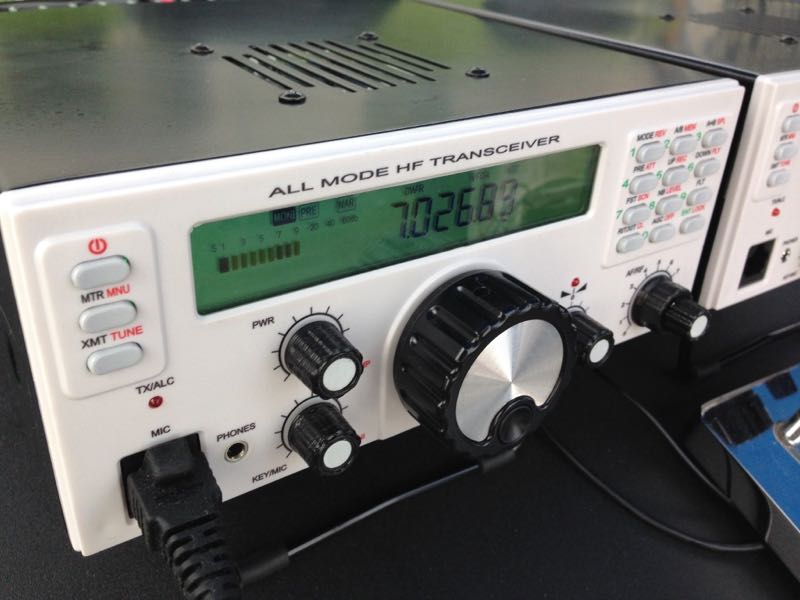
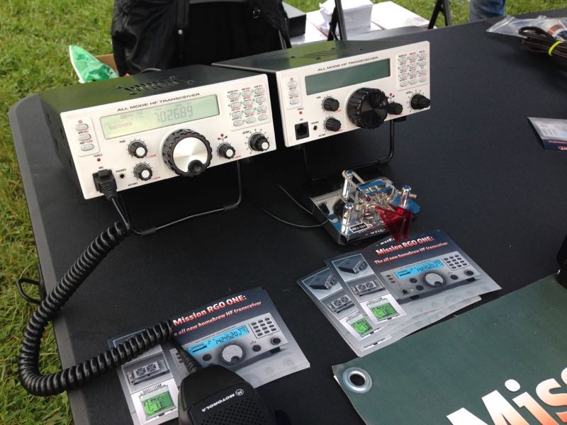
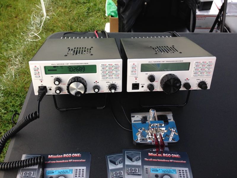
As you can see there is not much opportunity for grand antennas. And to add to this, the equipment I have in Sweden is also limited to a single 5-Watt unit.

My limited equipment – only 5-Watts.

The Design Thoughts

Today I have no area of land to use for antennas. I have a glassed-in balcony on the 4th floor of an apartment block. I really like the 20m (14MHz) band so I will concentrate on that. I am not really interested in the CW end of the band, except perhaps 14.070MHz for the digimodes. So my requirements are:

  • As efficient as possible (useable)
  • Small size, also portable so I can use it for field use
  • No expensive components, everything available locally
  • No TVI, QRM or interference to stereos or computer sound
  • Total price less than $2

The antenna I have created is based on my original 3.5MHz loop (or frame) antenna. This time I built it out of scrap components. I cadged (tiggade) some plastic conduit tubes from an electrical contractor at work. The same guy also gave me the remnants of a roll of 2.5mm C.S.A. multi-strand mains cable. That was all I needed.In my junkbox I found no tuning capacitors, but WAIT!! Why do I need to tune the antenna? Once it is tuned I should not need to tune it again, just set the centre-frequency to 14.175MHz. If I can get the Q-factor to around 100 then my useable 3dB bandwidth should be more than 150kHz. That will give me 14.10MHz to 14.25MHz.

Ok, I need a 1-off, preset tuning capacitor. Why not use a Gimmik Capacitor? Just twist two bits of wire together and cut it short to get the resonant frequency I want. So I need to get the coil wound so that there is sufficient cable length and self capacitance to give a resonance of about 14.5MHz without any extra capacitance what-so-ever. That means I need just a few pf. That sounds like a good plan.

Construction

The 15mm Diameter plastic tube I “aquired” were 80cm long. After much trial and error I found that exactly 3 turns, with 2.5cm spacing, gives about 14.9MHz self resonance. The wire support holes are exactly 4cm spaced, beginning 1cm from the end of each tube. The two tubes are fixed into a and X using zip-straps (tie-wraps, buntband). The feed loop is 1/2 turn.

Note the size and position of the feed loop. Also the Gimmik capacitor.

One problem I had with the original loop antenna was that of RF coming back down the cable braid. Using on old FT-101ZD it was possible to feel the RF on the microphone with your lips. The cure for this is to use a balanced feed and at least 5m of RF cable.

I robbed the ferrite ring for the balun from an old ATX computer PSU and made a triflar wound torroidal transformer. That is to say, twist together three lengths of 1mm x 7-strand insulated hookup wire together. Use this to make a 7-turn coil and connect the three coils in series, with four connections. Feed connections (numbered in the picture below) 1 and 3 are connected to to the antenna feed loop. Connect the coaxial cable braid to connection 2, and the coax centre to connection 4. My balun is self-supported on the connection leads.

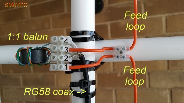
The 1:1 Balun I used.

The coaxial feed cable was found to affect the resonance slightly, so I fed that through an extra bit of tube to make it stay in one place. It works fine.

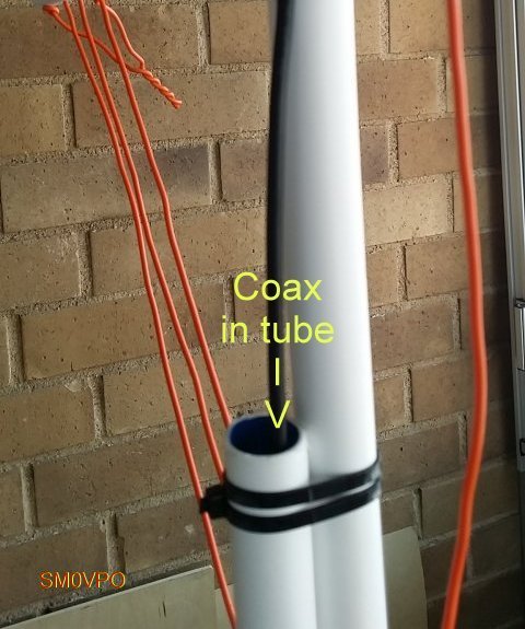
Feeder cable secured in the support tube.

Testing

Testing is very easy. I used my GDO-2 to check the middle-turn of the loop for a dip. Twist the two tails together to form the Gimmik capacitor and adjust the length of the twist until the centre-frequency is 14.175MHz. With the GDO you can get it within about 100kHz to 200kHz, but then you can check the VSWR using your HF radio. You can also sweep the band for maximum noise and get a very close approximation.

The Gimmick capacitor.

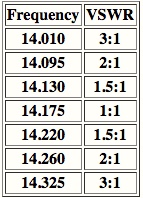
The centre frequency of my 20m Loop antenna is 14.175MHz, and the VSWR is better than 1.05:1 (I can hardly see any movement on my meter). The Q-factor is somewhere approaching 100. The useable bandwidth is just a little narrower than I would have wished, but the antenna certainly works well and meets all the other criteria. But the slightly less useable bandwidth criterion is at the expense of better performance, and it still allows me to use 14.070MHz, although it is a little quieter down there.

The completed antenna.

Conclusion

No-matter how you play with the figures, the best indoor antenna cannot replace a full-size dipole antenna. But the indoor antenna can give some extra features, such as just reaching out your arm and trimming a little, which you cannot do with a long-wire antenna up a tree out in the garden, especially when it is raining.

This antenna gets me on the air on 14MHz, and it has a useable frequency range. The VSWR is almost perfect at the centre-frequency, and this time I don’t burn my lips on the microphone (not that I am likely to do so with just 5-Watts of power). The design uses no expensive components, in fact the only item I bought was the block-connector for the balun. That cost me US$1.50 for a pair of 12-contact screw-terminals. The construction is ridiculously simple and easy to build.

On the air I can hear traffic on 14.070 digimodes, and from 14.130 to 14.220MHz I have a near-perfect VSWR aqnd good clear reception of SSB. I can also rotate the antenna to cut out rubbish, and most of all, using the Gimmik capacitor I don’t need to re-tune it: it seems temperatore-stable. The weight is less than 500g and when I poke it out of the balcony window the reception improves, the VSWR does not change, and I can make myself heard among the big boys.

I hope that you have some fun building and using this antenna. If you have any ideas for further improving it then please use my forum.

Don’t forget to visit my messageboard if you have any questions about this or any other project. I always look forward to receiving feedback, positive or negative.

Very best regards from Harry Lythall
SM0VPO (QRA = JO89WO), Märsta, Sweden.
EA/SM0VPO (QRA = IM86BS), Nerja, Spain.


Many thanks, Harry, for sharing this excellent project on the SWLing Post!

Post Readers: be sure to check out Harry’s website which is loaded with radio projects of all stripes. You’ll easily spend a few hours digging through his tutorials and downloads. Harry also maintains an alternate mirror server located here.

Side note: I’m impressed with the fact that the main SM0VPO website is actually hosted on a bedside Raspberry Pi computer (running the Linux-based Lighttp server).  Very cool!

Check out other homebrew mag loop antenna projects on the SWLing Post by clicking here.

The Mission RGO ONE: A new 50 watt all mode HF transceiver

Shortly after posting a set of photos I took at the 2018 Hamvention, I received a number of reader inquiries regarding one particular radio: The Mission RGO ONE.

I found this cool tabletop transceiver in the flea market area of the Hamvention early Saturday morning and included it with my inside exhibits photos. I wasn’t able to gather a lot of information from the representative at the time because the Hamvention staff opened the gates to general admission a full 30 minutes early, so I had to make a sprint to my table at the other side of the fairgrounds.

The following specifications/features were listed on the RGO ONE product sheet:

  • QRP/QRO output 5 – 50W
  • All mode shortwave operation – coverage of the 9 HAM HF bands (160m optional)
  • High dynamic range receiver design including high IP3 monolithic IC in the front end and H-mode first mixer
  • Low phase noise first LO – SI570 chip
  • Full/semi QSK on CW; VOX operation on SSB.
  • Down conversion superhet topology with 9MHz IF
  • Custom made crystal filters for SSB and CW and variable crystal 4 pole filter – Johnson type
  • Stylish and professional look
  • Compact and lightweight body
  • Multicolor FSTN LCD
  • Silent operation with no clicking relays inside
  • Modular construction – Mother board serves as a “chassis” also fits all the external connectors, daughter boards, inter-connections and acts as a cable harness.
  • Optional modules – NB, AF, ATU, XVRTER
  • PC control via CAT protocol; USB FTDI chip
  • Memory morse code keyer (Curtis A, CMOS B)
  • Contest and DXpedition conveniences

For even more detail, I recently contacted the rig’s developer, Boris Sapundzhiev (LZ2JR), who kindly answered all of my questions.

Boris replied:

Hello Thomas,

Thanks a lot for your message and interest about our new homebrew project that we called RGO ONE. Here you can find more about the radio:

QRP HF Transceiver

There are clickable highlights on the text which lead to a schematic diagram for each module so you can have a look if you like. Final documents and last revision of schematics will be available soon.

The idea of this project was inspired of an old TEN-TEC radios with 9MHz IF – their perfect analogue design and crystal crisp audio both CW and sideband. Mine have two very old TEN-TEC ARGOSY 525D and several moreTEN-TEC equipments. So with the help of the new electronic components available on the market we realize this old concept…

We’ve been working hard for almost three years to see what you saw at Dayton flea market table. A real performing HF 50W CW/SSB transceiver. We are 4 people in the team.. Other team mates are very good in industrial electronics manufacturing and helping very much with electronic PCB design, parts delivery, microprocessors and other things.

The idea of the front panel and other constructions design is mine .. I literally drew it in a couple of hours then our CAD designer put it in AUTOCAD/INVENTOR 3D design software.

Click to enlarge.

Click to enlarge.

Click to enlarge.

LCD we made in China and already stocked plenty of LCD and backlight units. Front panel is made by means of plastic mold method:

Here it is:

FACE PANEL MOLD PLASTICS OR ALUMINUM MACHINED

So far we got two samples that we tested already in real conditions and made several contest (LZ2RS helped with this task).

You can seek for video clips on YouTube (my channel) to see how it works.

Click here to view on YouTube.

I am back in Bulgaria now and today we had a team meeting so it is decided to start first lot 10pcs which will be completely ready to run. The time range of this is somewhere next two months. Then next lot will be 100 units probably some of them or most of them will be in a kit form with ready populated SMD small foot print components.

At the show in Dayton we revealed our target price for the base version – $450-$550. Hope to keep it as promised but final price will be available when first units come to alive.
First units will ship from Bulgaria, then we will try to stock more units in US.

This is briefly about our intentions of the project. A lot of interest, expectations and positive “WOW” feedbacks received so this urge me to go fast forward.

73, GL

Boris LZ2JR/AC9IJ

Thank you for the detailed reply, Boris! I will certainly follow this project with interest and post updates (readers: bookmark the tag RGO ONE).

I love the size of the RGO ONE and the fact it’s capable of a full 50 watts out in such a portable form factor. The front panel is very attractive, ergonomic and the backlit LCD screen is quite easy to read at any angle.

Boris, if you manage to hit your target price of $550 or less, you’ll no doubt sell these by the hundreds! I’ll be watching this project with interest.

Balazs spots radios in several movies and Netflix series

Many thanks to SWLing Post contributor, Balazs, who has spotted a number of radios recently on Netflix. Balazs notes:

The Snow Walker (2003): Barry Pepper tries to fix a radio:

Maze Runner – The Death Cure (2018): as scanners:

The Rain – new Danish post-apocalyptic series from the Netflix: field comm found:

Many thanks for sharing these, Balazs!

Post readers: Do you recognize these radios? One looks a lot like an Icom marine radio. Please comment!

95th anniversary of Czech radio’s first broadcasts

Czech Radio’s main headquarters in Vinohradská street in the centre of Prague, photo: Lenka Žižková

Many thanks to SWLing Post contributor, David Iurescia (LW4DAF), who shares the following news items from Radio Prague regarding the 95th anniversary of Czech Radio’s first broadcasts:

Listening Sessions at a Prague Cinema: Czech Radio’s First Broadcasts Recalled, 95 Years Later

A historic moment occurred at 20:15 on Saturday May 18, 1923 when the first ever broadcast by Czechoslovak Radio was made from a tent at a military air base in Prague’s Kbely district.

After the United Kingdom, Czechoslovakia was the second country in Europe to launch regular radio broadcasting.

Zuzana Foglarová is communications manager at today’s Czech Radio. Speaking at a new exhibition of radio technology at the station, she describes the scene in May 1923.

“Above all it was very simple. There was one tent, which had been borrowed from the scouts. On the floor in the tent was a piano and stool. There was also a table for the presenter, technicians and so on. There was only one microphone, and the story goes that if somebody was playing the piano and somebody else was singing, the latter had to sit under the piano so the microphone could pick up all the sounds.”

Many of the first listeners 95 years ago were waiting to hear the signal come through at a cinema just off Prague’s Wenceslas Square.[…]

Click here to download recording.

Click here to read the full article at Radio Prague.

The spectacular Rudgers?v Palace built in the Neo-Classicist style is home to Czech Radio’s Ostrava studios, photo: Daniel Martínek, Czech Radio (Source: Radio Praha)

Past and Present: A Gallery of Czech´s Radio Buildings

Czech Radio is celebrating its 95th anniversary this year. The Czech national radio broadcaster has come a long way since its pioneering days. Today it is the biggest radio broadcaster in the country with 9 channels, manned not only by its Prague staff but 14 regional branches providing news and reports from around the country. The station’s buildings are also an important part of its history. On the occasion of Czech Radio’s 95th anniversary we have prepared a photo gallery of its buildings, some of them valuable architectural landmarks.

Click here to view the photo gallery at Radio Prague.

VORW Radio International updated schedule

Many thanks to SWLing Post contributor John with TheReportOfTheWeek who writes:

Since our last update, a few additional time and frequency changes have been made to our shortwave airings of VORW Radio Int. Each broadcast features a fun hour of misc talk and commentary as well as a wide variety of listener requested music!

The full schedule is below, with changes being highlighted.

Thursday 1000 UTC – 5950 kHz – WRMI 100 kW – Western North America
Thursday 2000 UTC – 7780 kHz – WRMI 100 kW – Eastern North America
Thursday 2100 UTC – 7490 kHz – WBCQ 50 kW – Eastern North America
Thursday 2200 UTC – 9955 kHz – WRMI 100 kW – South America
Friday 0000 UTC (Thu 8 PM Eastern) – 7730 kHz – WRMI 100 kW – Western North America
Friday 0000 UTC – 5950 kHz – WRMI 100 kW – Central America (ex. 9455 kHz)
Friday 0000 UTC – 9395 kHz – WRMI 100 kW – North America
Friday 0100 UTC – 7780 kHz – WRMI 100 kW – Eastern North America & Europe
Friday 0100 UTC – 5850 kHz – WRMI 100 kW – North America
Friday 0400 UTC – 7730 kHz – WRMI 100 kW – Western North America (new. Test transmission for West Coast Listeners)
Sunday 2000 UTC – 9395 kHz – WRMI 100 kW – North America
Sunday 2100 UTC – 7780 kHz – WRMI 100 kW – North America

Questions, comments, reception reports and music requests may be sent to [email protected] PayPal donations are also welcome at that email as this is a listener funded broadcast.

Reception reports will receive a QSL!

All the best,

John