The following review was first published in the September 2020 issue of The Spectrum Monitor magazine:
The HobbyPCB IQ32 transceiver fills a special niche in the ham radio world
This summer, I’ve been exploring the world of general coverage QRP transceivers. I’ve been taking my LnR Precision LD-11, Elecraft KX3 and KX2 into the field; and I’ve just finished a comprehensive review of the Xiegu G90. I also have a TX-500 and IC-705 arriving in the near future [update].
Yes, I’ll admit, I’m a devotee of the “all-in-one” nature of the latest model portable QRP transceivers.
Most of the QRP transceivers now on the market are products of large, popular ham radio manufacturers. Usually, a company will come up with a product concept, follow through with their market research, then design, develop, and produce the radio. In fairness, that’s an over-simplification of the process, but let’s just call it a “top down” design approach––meaning, the product idea is generated within the company, and is often based upon customer feedback.
Not all ham radio products come about this way, though. Some have more “grassroots” or collaborative origin.
The HobbyPCB IQ32
(Image Source: HobbyPCB)
I first noticed the HobbyPCB IQ32 transceiver at the Dayton Hamvention a few years ago. I checked it out carefully at their booth, and recall a crowd gathering around their table. Noting this, I decided, at a later time, I would also find an opportunity to check out the radio in more detail.
A couple of months ago, I was working on my list of General Coverage QRP Transceivers and asked for help filling in details of any radios I’d forgotten. A reader commented and reminded me that the IQ32 was, indeed, general coverage.
At this point, I reached out to HobbyPCB and asked for a loaner unit to explore for a few weeks. The company very kindly sent one my way some weeks ago, and I’ve been testing it on the air ever since.
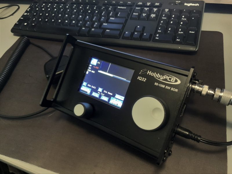
Form factor
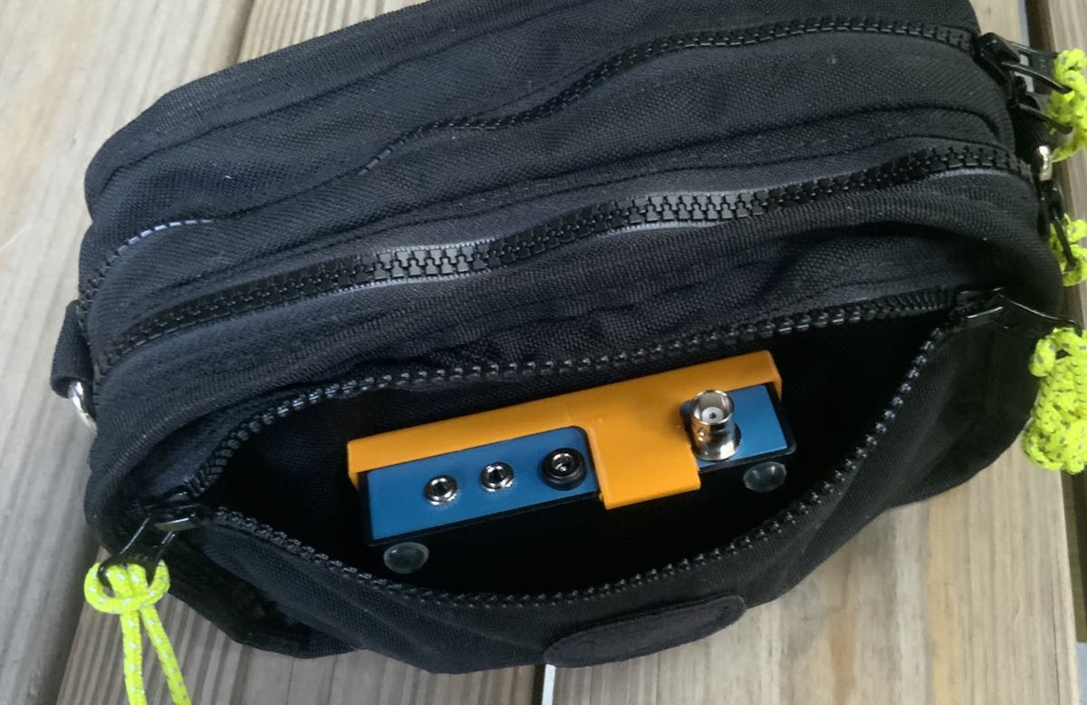
When I received the IQ32 package, I was surprised by how lightweight this transceiver is: a mere 1.5 lbs (700 grams) packs it all in one compact package.
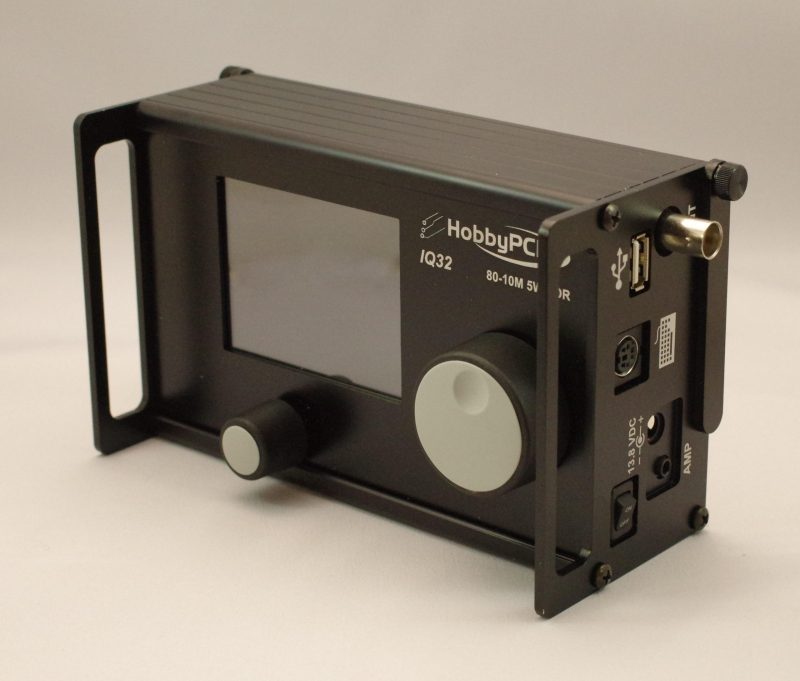
The chassis is made of aluminum and incredibly sturdy. It even includes side panel extensions to protect the front faceplate and knobs.
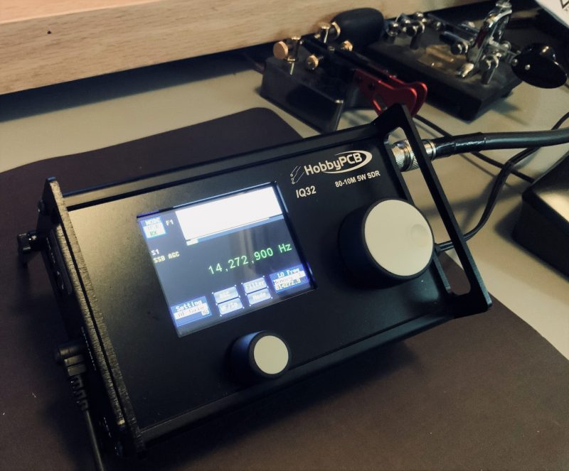
The IQ32 sports a 3.2″ color LCD touch-screen display large enough to contain all of the functions, a spectrum display, and even an area for text––both transmitted and received in PSK31 and CW. The display is reminiscent of the uBITX V6 I recently reviewed. It is recommended that the operator uses a blunt plastic stylus (or retracted ballpoint pen) for navigating the color screen, since several of the menu settings, memories, and the like require some fairly precise tapping. The graphic user interface (GUI) feels a bit like what I’d expect to find on a piece of test equipment: a bit old school, but nonetheless quite functional.
The main encoder and selector knobs are lightweight and made of some sort of plastic or nylon. They work quite well––but if I owned an IQ32, I believe one of the first things I’d do is replace those with a lightweight aluminum equivalent.
As I mentioned earlier, the weight of the IQ32 is very reasonable at 1.5 lbs. I don’t think I’d even notice it packed in a backpack.
The IQ32, like the recently released Lab599 TCX-500, lacks an internal speaker. However, my unit came with a speaker microphone, which works fine.
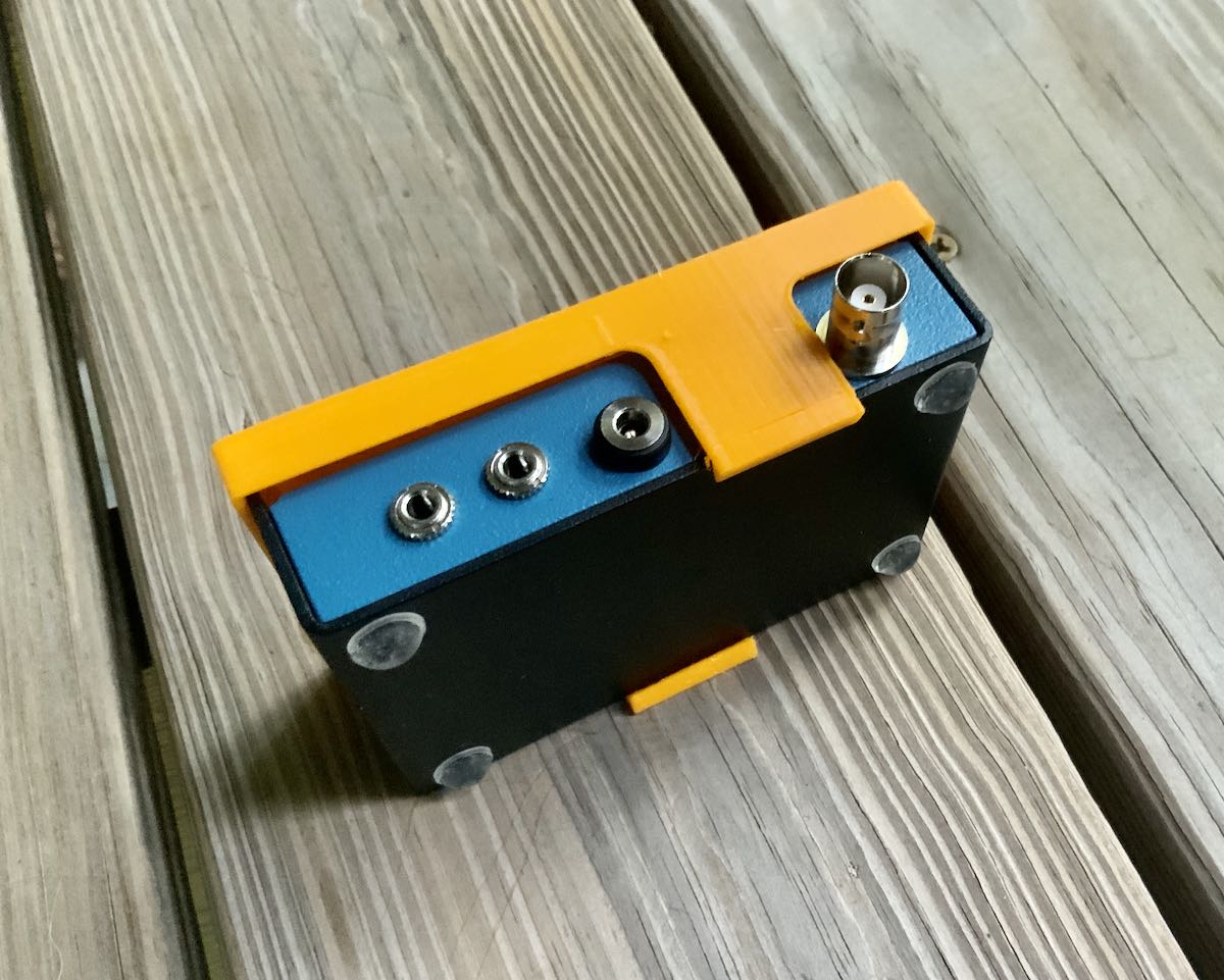
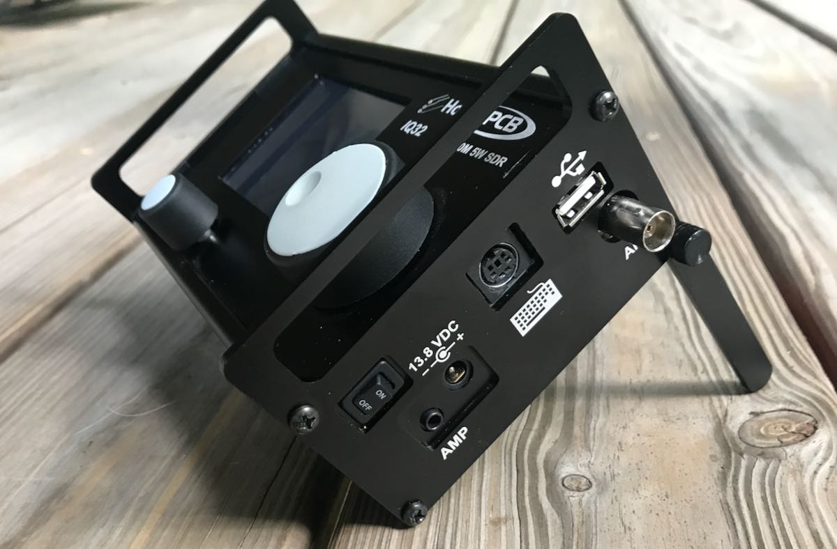
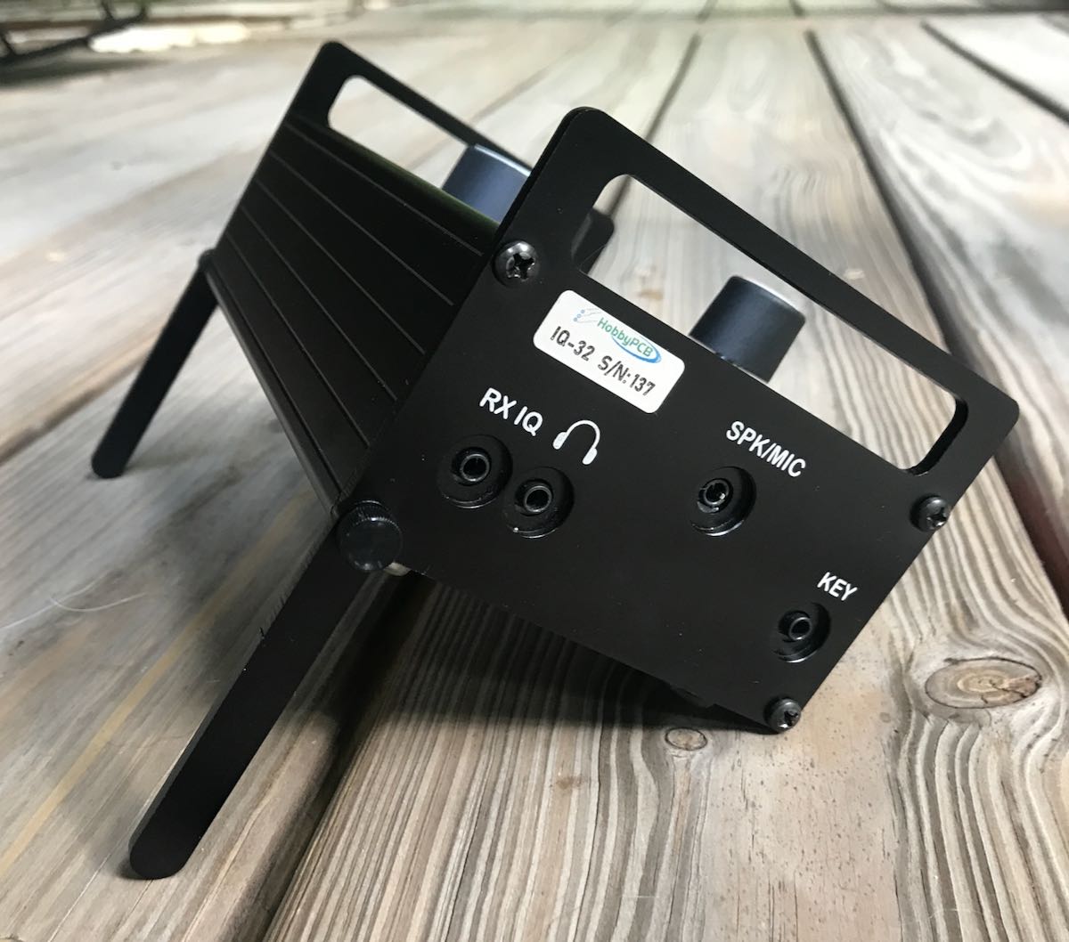
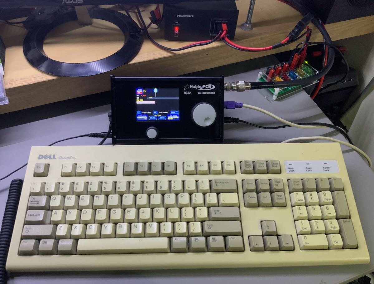
The right side panel of the IQ32 has a toggle power switch, power amplifier connection, power port (5mm X 2.1mm, positive tip), PS2 keyboard connector, USB Type A, and a BNC antenna port. The left side has a 3.5mm I/Q Output, 3.5mm headphone jack, 3.5mm speaker/mic port, and a 3.5mm CW key input.
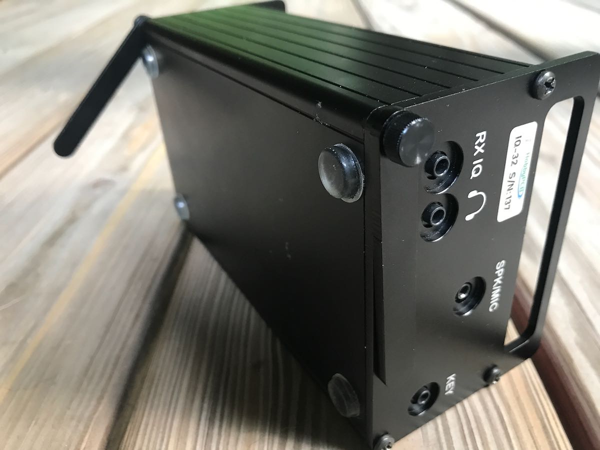
The IQ32 also has two legs that can be adjusted so that the radio will prop up at a comfortable angle for operation. The legs can be a bit finicky to adjust and keep in place, so I preferred using an angled radio support I use for my Elecraft KX3.
A collaboration
The IQ32 also feels like a project joint effort, bringing to mind the old chocolate-peanut butter cup commercial of a bygone era: “My chocolate got mixed with your peanut butter!” And or, “My peanut butter got mixed with your chocolate!”
Curious about this seeming blend of radio ideas, I reached out to Jim Veach (WA2EUJ) at HobbyPCB for more information; he gave me a little history behind the IQ32.
Jim writes:
The IQ32 is the fusion of two products: the HobbyPCB RS-HFIQ, and the STM32-SDR.
The RS-HFIQ was designed to be a 80-10M, 5W soundcard-based SDR––similar to the popular Softrock SDRs with some expansions and revisions.
The STM32-SDR was designed to work with a soundcard-based SDR and [thus] eliminate the need for a PC and provide stand-alone operation.
Inside the IQ32 is a mostly stock RS-HFIQ (in fact, we offered an upgrade kit so RS-HFIQ owners could go the IQ32 route) and a custom version of the STM-32 […] specifically for the IQ32.
The original development of the STM32 [began] a few years ago when PSK31 was the digital mode du jour and [the] PS2 keyboard roamed the land. The firmware team recently released the current FW, which greatly expanded the CW modes and reworked the memory structure based on user input.
And there you have it: even though this unique little rig has been around for a few years, I’m impressed that they continue to refine it and upgrade the firmware. Indeed, if the community of IQ32 users grow, they may be able to do even more.
On the air
 To be clear, my intention here isn’t to conduct a comparative review of the IQ32. I simply want to convey what I’ve learned in the process of playing with the rig and trying out some of its unique features.
Immediately after unboxing the radio, I hooked it up to my main skyloop antenna, plugged in the power supply that accompanied the radio, then plugged in the handheld speaker mic.
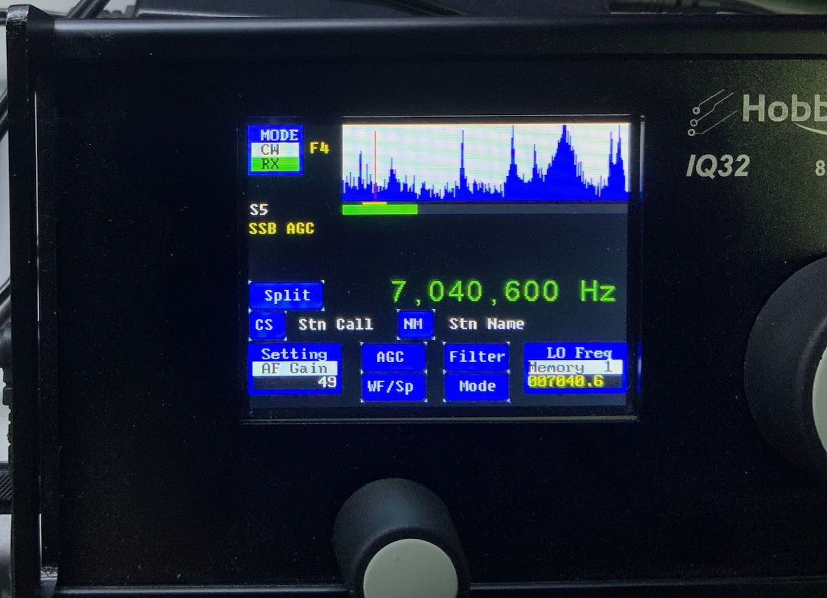
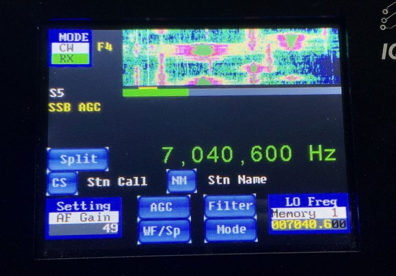
I discovered rather quickly that the IQ32 user interface takes a different approach than any other transceiver I’ve ever tested. Instead of one main user interface window in which you navigate modes, frequencies, and perhaps alter spectrum and bandwidth settings, the IQ32 has a different screen layout for each mode. It’s as if each mode––SSB, PSK31, CW, etc.––has its own “page.”
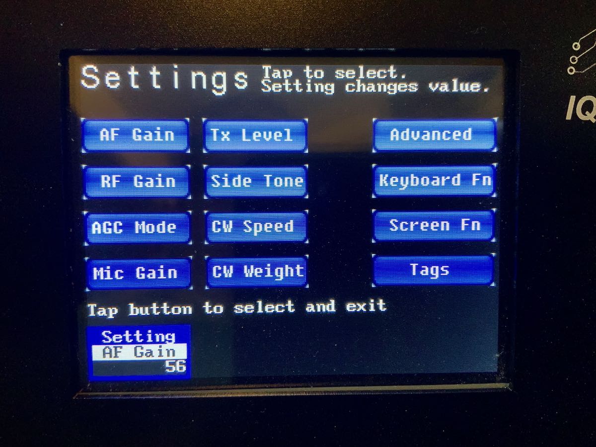
Despite the very minimal controls, you can adjust many of the IQ32s settings, macros, and memories in a very granular way via the settings pages using a stylus for fine control of the screen. On the flip side, during operation, it can be frustrating when adjustments need to be made quickly between the AF Gain, RF Gain, CW Speed, and AGC, as they all use the same multi-function knob and switching between them requires several screen taps––not as quick a process as one might prefer.
Indeed, the IQ32 isn’t immediately as intuitive as most commercially-marketed radios. But once you fully understand the settings and modes pages, it becomes easy to navigate. Note: I would advise any future owner of an IQ32 to read the manual in advance. I did this, and it certainly helped. I should add here that the IQ32 manual is one of the most comprehensive I’ve read––especially considering its collaborative roots.
Now, let’s talk modes.
SSB
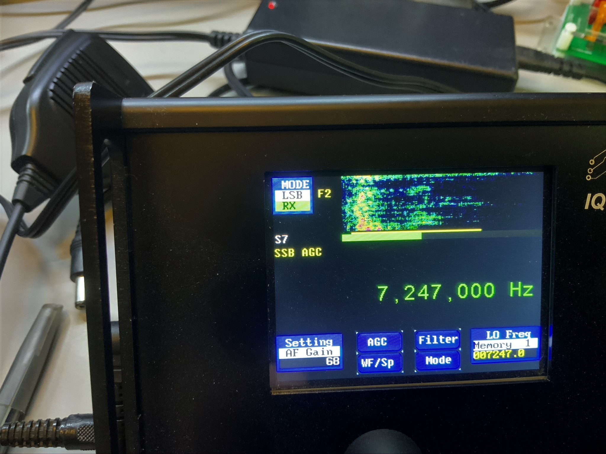 Since the IQ32 requires a PS2 keyboard for PSK31, and optionally for CW, I tried my hand at SSB first.
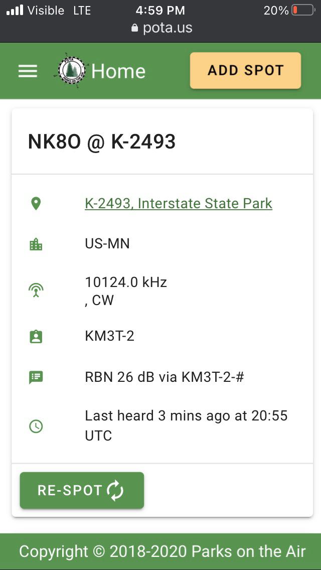
After learning how to switch modes and filter settings, I hopped on the air. Instead of calling CQ, I decided instead to seek a park activator in the POTA program via the POTA spots website. Within 10 minutes, I made contact with two parks: one in Pennsylvania and one in Florida on the 40 and 20 meter bands, respectively. While both parks gave me a “5×9” report, I seriously doubt it was accurate based on their own signal strength. (Some park activators, like contesters, only give 5×9 reports.)
Still, my success in contacting these two parks told me that the mic settings were probably suitable and that the audio had enough punch on 5 watts to be heard. To confirm, I called CQ a few times and listened to my own signal at a KiwiSDR site in Maryland. The signal was about 5×5, but the audio was clear, clean, and had excellent fidelity.
Over the past few weeks I’ve worked dozens of stations across North America with the IQ32.
PSK31
 One of the very unique features of the IQ32 is its ability to natively encode and decode PSK31. This was the second mode I was eager to try.
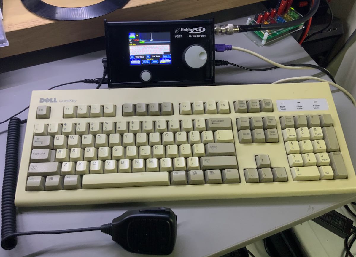
To use PSK31 on the IQ32, a PS2 keyboard (or USB keyboard with PS2 adapter) must be connected. I searched my shack in vain for a PS2 keyboard, but fortunately, my friend Vlado (N3CZ) came to the rescue and let me borrow one of his keyboards.
Again, note: IQ32 beginners should certainly plan to read the PSK31 section of the IQ32 manual prior to attempting a PSK31 QSO. For starters, you’ll want to enter in your personal information into the tags settings so that you can use your keyboard function keys to automatically send CQs and to answer calls. The manual will also walk you through any other necessary settings.
Once I had everything set up, I started calling CQ on the 20 meter band; unfortunately I had no luck snagging a station. This had less to do with the radio and much more to do with the mode, which has, alas, fallen out of popularity since the advent of FT8. It’s a shame, really, because although PSK31 is a digital mode, it feels much more like a proper QSO than FT8, in my opinion. While I have a lot of respect for FT8, with PSK31, you can, as we hams say, “rag-chew”––a much more personal interaction.
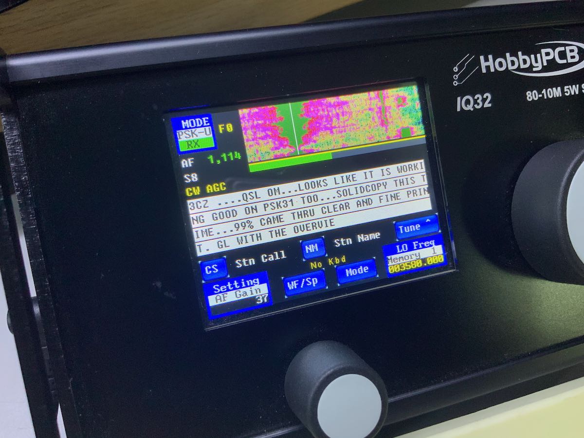
And rag-chewing is exactly what I did. I contacted a friend, we set a sched for a PSK31 QSO, and it was, indeed, fun. The IQ32 has a screen with enough text space so that it’s easy to follow and to read. In fact, with this radio, I don’t feel like a computer is needed.
With the keyboard attached, PSK31 just works…and works quite well. I really like the way this feature has been implemented in the IQ32.
CW
Truly, the IQ32 actually has a lot to offer the CW operator. The IQ32 supports Iambic keyer modes A and B, with speeds up to 35 wpm. You can also adjust the weight of the dits and dahs. The IQ32 doesn’t support full break-in QSK, however: there is a slight delay after sending before the relay puts the radio back into receive mode. At present, this delay is not manually adjustable but is, rather, based on the selected keyer speed.
I’ve been very pleased using the IQ32 in CW mode with my Begali paddles and Vibroplex single lever paddle.
Of course, a really unique feature of this rig is that it provides the operator with the means to use the PS2 keyboard to send CW, just as you can with the PSK31. At present, there is no CW decoder, but for those who feel their fist isn’t quite up to par, you can surprise the operator on the other end by sending perfectly formed and spaced CW by simply typing it on the keyboard. Herein lies a very unique feature and application for the IQ32.
Indeed, as a frequent Parks On The Air (POTA) field activator, I rely very heavily on memory keyers to call CQ, send a park number, as well as give my thanks and 73s to those who contact me. Using a pre-programmed message means that I then have time to log a station while it sends, and to ensure my code is cleaner when I send park numbers––especially since I don’t exactly excel at sending strings of numbers!
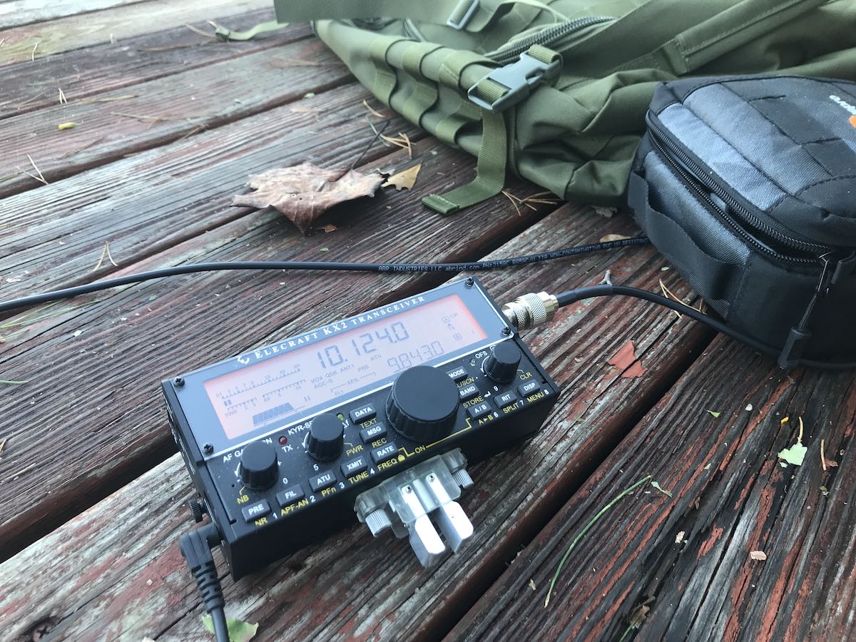
With the IQ32, I find I can program full CW messages to play when I simply press one of the function keys on the keyboard. This gives me much better flexibility and control than, say, the built-in memory keyer on my venerable Elecraft KX2.
With the IQ32, a CW op would actually have the choice of never even touching a key, and just sending all messages with the keyboard. While I could never see myself doing that (as I quite enjoy sending CW with a key), the flexibility of pre-programming an array of CW memory messages and having them conveniently at hand is nonetheless quite appealing.
As a CW operator, I’m quite pleased with the IQ32. My only wish would be for a slightly shorter relay hang time for use in contesting or on Field Day.
The IQ32 Niche
While I wouldn’t necessarily recommend the IQ32 as a first transceiver to a newly-minted ham, I can certainly envision a niche market for this unique rig.
For one, I think the IQ32 could satisfy those operators who desire a very clean and stable transmitter. The IQ32 sports a Class A 5-watt power amplifier with individual low-pass filters for each band that exceed FCC requirements for spectral purity. It also has a Temperature-Compensated Crystal Oscillator (TXCO) for frequency stability––truly, this is not common in a radio of this price class.
For another, the IQ32 could be used as a driver for a transverter when operating on VHF or UHF. Another of its unique and useful features is that the user can set an offset to display the transverter output frequency rather than the IQ32-driven frequency.
And, finally, let’s face it: I know of few other radios that you can take to the field, hook up a keyboard, and natively send and decode PSK-31 transmissions. My KX2 can do this to a degree, but I have to input the text as CW, and the number of characters in the display is quite limited. The IQ32 is robust enough to permit you to carry on PSK-31 rag-chews, if you wish. If this is your thing, you’ll definitely want to play with this rig.
Being able to send CW with a keyboard and pre-programmed messages also means CW operators could make their workflow much more efficient in either the shack or the field.
In conclusion, I’ll admit that the IQ32 isn’t as intuitive as other radios and that the ergonomics leave room for improvement. But it’s still a cool little radio. If, after having read this tour of the IQ32, you feel like you’re in this radio’s niche market, then definitely reach out to HobbyPCB: I’ve found their customer care and support to be absolutely benchmark.
All in all, I’ve had a lot of fun tinkering with this unique general coverage QRP transceiver; I expect others like me will, too. Many thanks to HobbyPCB and the IQ32 crew for letting me take a deep dive into this very special little rig!
Click here to check out the IQ32 at HobbyPCB.
Do you enjoy the SWLing Post?
Please consider supporting us via Patreon or our Coffee Fund!
Your support makes articles like this one possible. Thank you!


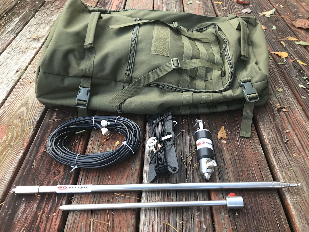 Chameleon Antenna recently sent me a prototype of their latest antenna: the CHA MPAS Lite.
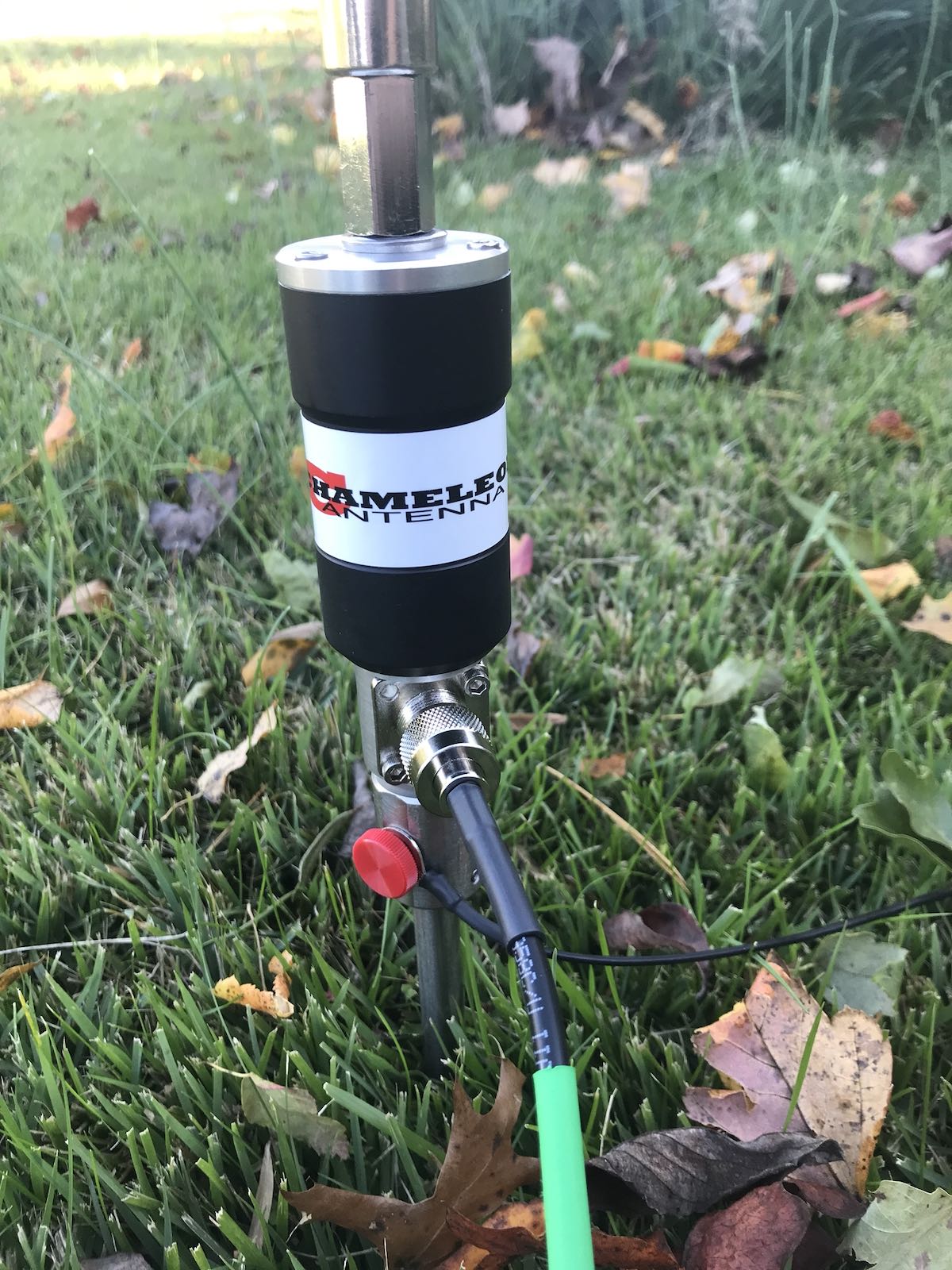

 He was working a bit of a pile-up, but after three calls, he worked me and reported a 559 signal report. Not bad at 5 watts!
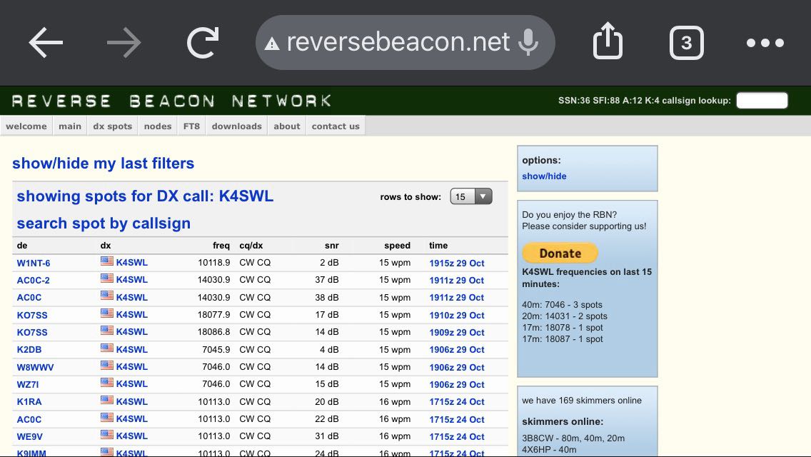
 Of course, after working a few stations in CW and SSB, I tuned to the broadcast bands and enjoyed a little RFI-free SWLing. Noting 13dka’s recent article, I’m thinking on the coast, the MPAS Lite will make for a superb amateur radio and SWLing antenna.
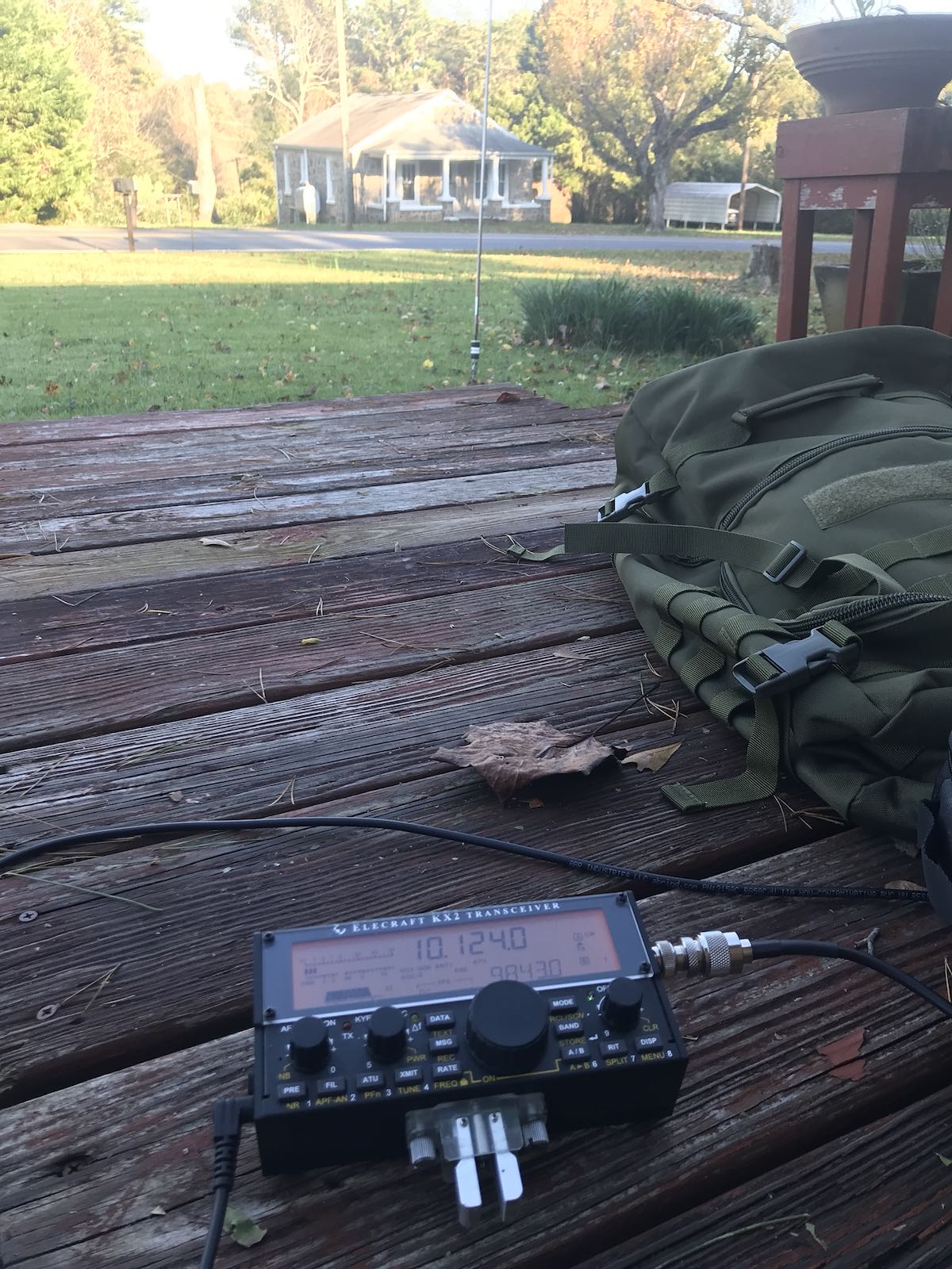
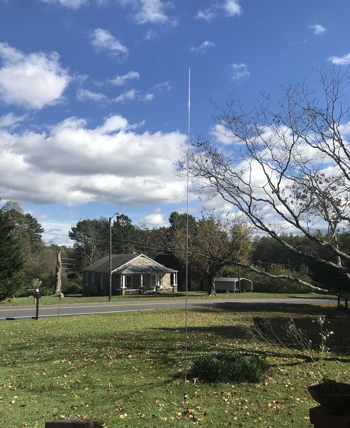 I’m a huge fan of wire antennas because I believe they give me the most “bang-for-buck” in the field, but they’re not always practical to deploy. I like having a good self-supporting antenna option in my tool belt when there are no trees around or when parks don’t allow me to hang antennas in their trees.