Monthly Archives: August 2022

The shortwave showdown of 2022

Hi all the SWLing post community. Fingers crossed all stops will be pulled out this weekend via WRMI with the broadcast of TOOTS vs WELK. This programme in the Imaginary stations series will be a showdown of music from Toots Thielemans in the left hand corner and the great Lawrence Welk in the right. The transmission will be on air on 9395 kHz from 2200 utc on Sunday 28th August 2022. Tune in for a great musical encounter!

And here’s a guide how to listen to Imaginary stations from the good folks there. Watch and enjoy. Fastradioburst23 

Spread the radio love

Video: Nick’s initial review of the Eton Elite Satellit

Many thanks to SWLing Post contributor, Nick Booras, who writes:

I bought [an Eton Elite Satellit] on Amazon and received it today. Here is a link to my YouTube review.

I have made several radio videos on YouTube recently and your audience may enjoy them.

Click here to view on YouTube.

Many thanks for sharing your initial review, Nick! I look forward to seeing any comparison videos you might produce as well!

Spread the radio love

The new Alinco DJ-X100 wideband receiver

It appears that Alinco will soon introduce a new wideband handheld receiver covering 30 to 470MHz. I first learned about this during Ham Fair 2022 in Tokyo via HamLife.jp’s Twitter account.  That Twitter account lead me to the HamLife.jp website where I translated the details into English via Google Translate:

On August 20, 2022, Alinco Co., Ltd. released the DJ-X100 handheld wideband receiver that supports WFM/FM/AM in analog mode and C4FM/D-STAR/DCR/NXDN/DMR in digital mode. , Announced at the company’s booth (B-17) at Ham Fair 2022. The reception frequency range is 30 to 470MHz (some frequencies are excluded), the external dimensions are 58W x 110H x 32.5mm, and the weight including the antenna and battery pack is about 260g. The price is undecided and it is scheduled to be released in early spring 2023.

This isn’t an HF receiver, but it will be interesting to those who enjoy monitoring many of the digital voice modes in those frequencies. It’s one of the few receivers I’ve seen that can decode both DMR and D-Star among others modes. 

Check out HamLife.jp for more details (in Japanese).

Spread the radio love

One last call for SDRplay RSP1A metal cases!

Many thanks to SWLing Post contributor Dave (N9EWO) who writes:

Thomas, FYI

RTL-SDR.com decided to make one LAST production run of the RSP1A metal cases. These are now available on Amazon for $34.95 until stocks run out.

73
Dave Zantow N9EWO.

Click here to view on Amazon (affiliate link).

Thank you so much for the tip, Dave!

Spread the radio love

Can you help Rob identify two mystery signals on the 20 meter band?

I received the following message from my buddy Rob (NC0B) who is trying to identify a couple of signals on the 20 meter band. Rob kindly gave me permission to post his email here on the SWLing Post with the idea that someone may be able to help him solve this:

The following is a description of two odd digital signals observed on 20 meters with transmission modes I do not understand. They may not amateur transmissions, but I have no way to decode them. They stick out like a sore thumb on 20m in the Extra portion of the phone band. The time of day on August 20th was between 11:50 AM and 12:00 PM MDT.

Two weeks ago I was in QSO on 14,170 kHz and occasionally there was the same 10 kHz wide digital signal but centered on 14,171 kHz. It sounded like the old Russian jammers buzz saw modulation. Those signals from decades ago were much wider, and or course we didn’t have high resolution spectrum scopes back then. Today the same transmissions occurred several times, and more than once a minute for about 5 seconds each. In total the transmissions may have occurred on and off for about 10 minutes.

Then after a few 10 kHz transmissions a different signal came on the air a few times with what looked like a digital modulated carrier plus digital sidebands on each side of the middle signal.

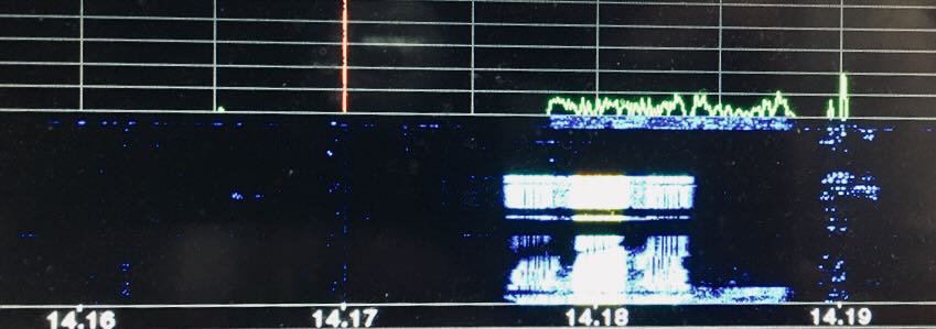
Look at the attached JPG file and I’ll try to make sense out of it:

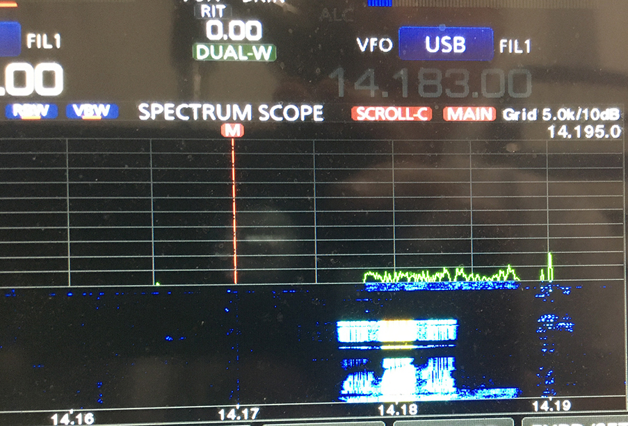
The waterfall image lasts about 50 seconds on the Icom IC-7610 set on slow. There are two different signals to differentiate in this image. The signal I observed two weeks ago and today is 10 kHz wide and today spans from 14,178 to 14,188. It shows up in green on the band scope, and just under it in blue on the water fall for about 3 seconds of the approximate 5 second transmission. You can also see at the bottom of the waterfall the previous transmission that has about 4 seconds worth saved on the waterfall running off the bottom. The horizontal span of the scope was set to 5 kHz per division.

Once the 10 kHz wide signal started, I went to Dual Watch so I could listen for KL7QOW on 14,170 kHz for a sked, and hear the buzzing signal on 14,183 kHz in SSB mode. That frequency placed the carrier position of the SSB 2.8 kHz bandwidth in the center of the 10 kHz wide signal.

Soon after I started observing the relatively flat spectrum of the 10 kHz signal, a new digital signal appeared about 3 kHz lower in frequency. At first it had a much stronger center modulated carrier about 2 kHz wide and then two symmetrical digital signals on each side within about a 6 kHz total bandwidth. I wasn’t able to capture the best picture of the 2nd signal as it appeared to be tuning up. The amplitude difference between the central signal and the separate sidebands initially was about 15 dB. Vertical divisions are 10 dB.

On the waterfall you can see the second type of signal is centered on about 14,180 kHz. The modulation depth of the outer pairs of signals were not constant, possibly due to selective facing. QSB was quite significant at this time at least to Alaska. You can see there was a short break of a few seconds in the 6 kHz wide signal. Every time I have seen the 10 kHz wide signal its amplitude across the transmission bandwidth has been fairly constant, always of short duration, and repeating several times within 10 minutes before terminating.

Does anyone have any idea what either of these transmissions are? I have heard of email digipeaters, but I would not think their bandwidth would be this wide.

Rob, NC0B

SWLing Post community: Please comment if you can help Rob ID these signals!

Spread the radio love

Small Unidirectional Loop Antenna (SULA) Part 2: Construction Notes

Many thanks to SWLing Post contributor extraordinaire, 13dka, who brings us Part Two of a three part series about the new SULA homebrew antenna project. This first article describes this affordable antenna and demonstrates its unique reception properties. This second article focuses on construction notes. The third and final article will essentially be a Q&A about the SULA antenna. All articles will eventually link to each other once published.

This wideband unidirectional antenna is an outstanding and innovative development for the portable DXer. I love the fact that it came to fruition via a collaboration between Grayhat and 13dka: two amazing gents and radio ambassadors on our SWLing.net discussion board and here on the SWLing Post. So many thanks to both of them!

Please enjoy and share Part 2:


Part 2: SULA Construction notes

by 13dka

The drawing [above] has all you need to know. You basically need to put up a symmetrical wire diamond starting with a balun at the one end and terminating in a resistor at the other end of the horizontal boom, the sides are supposed to be 76cm/29.92″ long so you need to make yourself some…

Support structure:

I used 0.63″/1.6cm square plastic square tubing/cable duct profiles from the home improvement market to make the support structure. You can use anything non-conductive for that of course, broom sticks, lathes… The plastic profiles I used had the advantage of being in the house and easy to work on with a Dremel-style tool and everything can be assembled using the same self-tapping screws without even drilling. The profiles are held together with 2 screws, for transport I unscrew one of them and put that into an extra “parking” screw hole on the side, then I can collapse the cross for easy fit into the trunk, a rucksack etc.

These profiles are available in different diameters that fit into each other like a telescoping whip. This is useful to make the support structure variable for experiments and to control the loop shape and tension on the wire. The booms end up at 1.075m each, the profiles come in 1m length, so that’s 4 short pieces of the smaller size tube to extend the main booms by 37mm on each side

On the resistor end of the loop that smaller tube isn’t mounted in the “boom” tube but to the side of it in order to keep the wire running straight from the balun box on the other side.

Mast/mounting:

You can use anything non-conductive to bring it up to height. On second thought that is indeed bad news if you were planning on putting that up on your metal mast…and we have no data on what happens when you do it anyway. I don’t know if the smallest (4m) telescoping fiberglass poles would suffice for portable operation, but I’m a fan of just using the big lower segments of my 10m “HD” mast for the stiffness they give me (3 segments for the height, the 4th collapsed into in the base segment for easy rotation). Telescoping masts also give you easy control over…

Height:

The published patterns are for 3m/10′ feedpoint height over “average” ground. Increasing height further has no expectable advantage, instead it will deteriorate the favorable directional pattern of the loop. Flying it lower, or even a lot lower in windy weather on the other hand is causing a surprisingly moderate hit on performance.

Continue reading

Spread the radio love