The following article first appeared in the January 2020 issue of The Spectrum Monitor magazine.
The AirSpy HF+ Discovery and a new era of portable DXing
I admit it: I used to be a bit of an old-fashioned radio curmudgeon. One of those, “I like my radios with knobs and buttons” likely followed by, “…and no other way!”
However, about fifteen years ago, many of my DXing friends started turning to the world of software defined radios (or in common parlance, “SDRs”). I staunchly opposed ever following in their footsteps. One of the reasons I for this––a good one––is that, since I spend the bulk of my day in front of a computer, why would I ever want to use a computer when I’m playing radio?
But then…gradually, I found myself playing around with a few SDRs. And I quickly learned that third-generation SDRs were capable of doing something very impressive (and fun), indeed: making spectrum recordings. Using this tool, I found I could record not only the audio of one individual signal, but the audio of entire swathes of radio spectrum. And even more impressive, I learned that you could later load or “play back” the spectrum recording and tune through the bands as if in real time. Any time you want. Before long, I was hooked: SDRs had become my portal into radio time travel!
I quickly found that I loved many of the other advantages of using an SDR, as well, including visual ones––like the ability to view spectrum. The interactive interface allows one to actually see radio signals across the band in real time. I also found incredible value in waterfall displays, which show signals changing in amplitude and frequency over time. Cool stuff.
I purchased my first dedicated SDR in 2012, a WinRadio Excalibur. It was––and still is––a benchmark receiver, performing circles around my tabletop receivers and general coverage transceivers.
And today, although I own and love a number of legacy radios and still listen to them in the good old-fashioned manner to which I became accustomed, I find I’m now spending the bulk of my time DXing with SDRs.
And then, more recently, two amazing things happened in the world of SDRs. Strong market competition, together with serious innovations, have come into play. Thus, for less than $200 US, you can now purchase an SDR that would have easily cost $1,000 US only ten years ago. And now, in many cases, the $200 SDR of today will outperform the $1,000 SDR of yesteryear. We are, indeed, living in good times.
And now––no more a radio curmudgeon––I’m comfortable with my SDR-user status and time at the computer, and glad I was just curious enough about SDRs to let them into my radio (and computer) world.
Portable SDRs
Since I initially dived into the world of SDRs, I’ve tried to think of a way to take them into the field.
But first, let’s get an obvious question out of the way:
Why would you want to drag an SDR into the field, when a traditional battery-powered radio is so much easier to manage?
After all, you may say, portable and even mobile tabletop receivers require no computer, no hard drive, and are likely more reliable because there are less components to manage or to cause problems for you.
In answer, let’s look at a few scenarios where heading to the field with an SDR system might just make sense. (Hint: Many of these reasons are rooted in the SDR’s ability to record spectrum).
Good Reason #1: Your home location is not ideal for playing radio.

Photo by Henry Be
My good friend, London Shortwave, lives in the middle of London, England. He’s an avid radio enthusiast and DXer, but his apartment is almost a perfect storm of radio interference. Listening from his home is challenging, to say the least: he can only use indoor antennas and RFI/QRM simply inundated his local airwaves.
Many years ago, he discovered that the best way to DX was to go to an area that put urban noise and radio interference at a distance. He found that by visiting large local parks, he could play radio with almost no RFI.
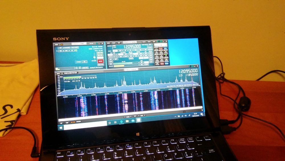
Being a computer guru, he started working on a portable SDR setup so that he could go to a park, set up an antenna, and record radio spectrum while he read a book. His systems evolved with time, each iteration being more compact less conspicuous that the previous. Later, he could head back home, open the recorded spectrum files, and tune through these “time-shifted” recordings in the comfort of his flat. This allowed London Shortwave to maximize the low-RFI listening experience by reliving the time in the park.
Over the years, he tweaked and adapted his setup, often writing his own code to make small tablets and portable computers purpose-built portable-spectrum-capture devices. If you’re curious, you might like to read about the evolution of his systems on his blog.
Clearly, for London Shortwave, an SDR is the right way to capture spectrum and thus likely the best solution for his DX listening.
Good Reason #2: Weak-signal workarounds.
Typically radio enthusiasts turn to field operation to work in a lower-noise environment and/or where there are no antenna restrictions, often to log new stations and DX.
SDRs afford the DXer top-shelf tools for digging weak signals out of the muck. SDR applications have advanced tools for tweaking AGC settings, synchronous detectors, filters, noise reduction, and even to tailor audio.
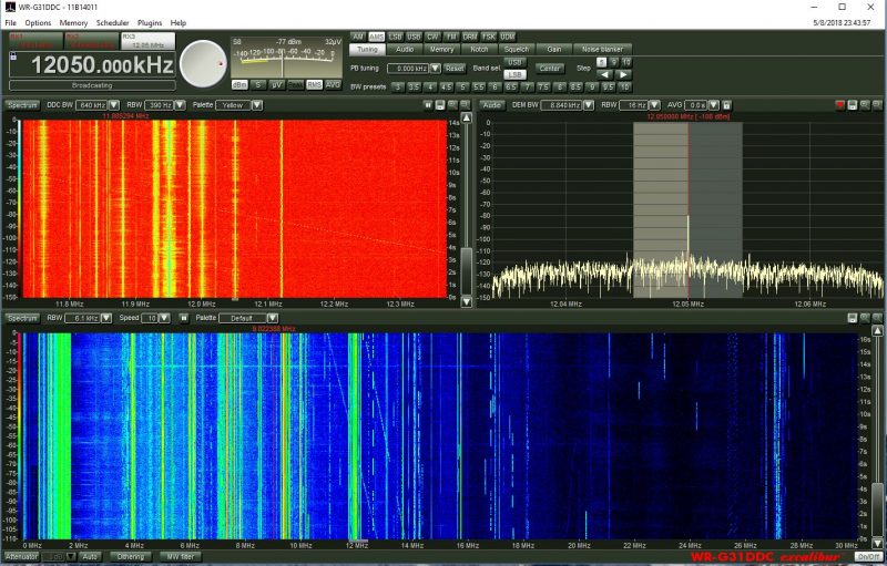
The WinRadio Excalibur application even includes a waterfall display which represents the entire HF band (selectable 30 MHz or 50 MHz in width)
On top of that, being able to see a swath of spectrum and waterfall gives one an easier way––a visual way––to pinpoint weak or intermittent signals. This is much harder to do with a legacy radio.
Case in point: I like listening to pirate radio stations on shortwave. With a spectrum display, I can see when a new station may be tuning up on the band so can position the receiver to listen in from the beginning of the broadcast, and never miss a beat.
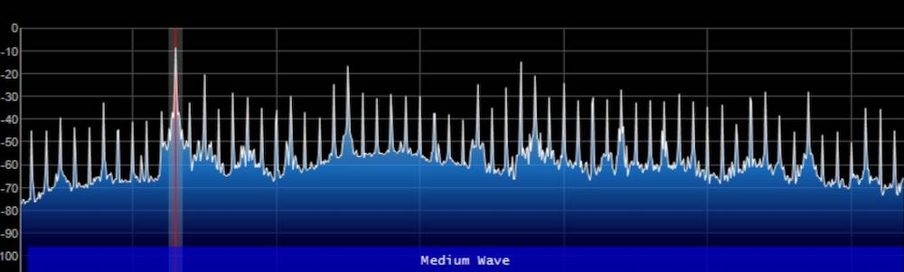
Or, in another example, the visual aspect of spectrum display means I can easily locate trans-Atlantic DX on the mediumwave bands by looking for carrier peaks on the spectrum display outside the standard North American 10 kHz spacing. The signals are very easy to spot.
Good Reason #3: DXpeditions both small and large.
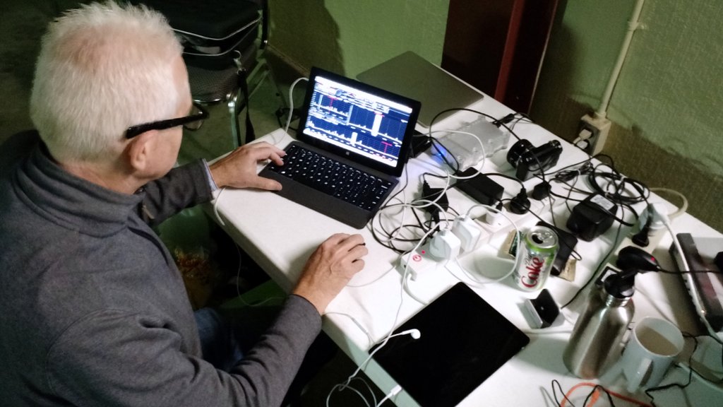
Mark Fahey, scanning the bands with his WinRadio Excalibur/Surface Pro 2 combo at our 2015 PARI DXpedition
Whether you’re joining an organized DXpedition or you’re simply enjoying a little vacation DXpedition, SDRs allow you to make the most of your radio time.
Indeed, most of the organized DXpedition these days heavily incorporate the use of SDRs specifically so DXers can record spectrum. Much like example #1 above, doing this allows you to enjoy the noise-free optimal conditions over and over again through spectrum recordings. Most DXpeditioners will have an SDR making recordings while they use another receiver to DX in real time. Later, they take the recording home and dig even more weak signals out of the mix: ones that might have otherwise gone unnoticed.
Good Reason #4: Sharing the spectrum with like-minded listeners.
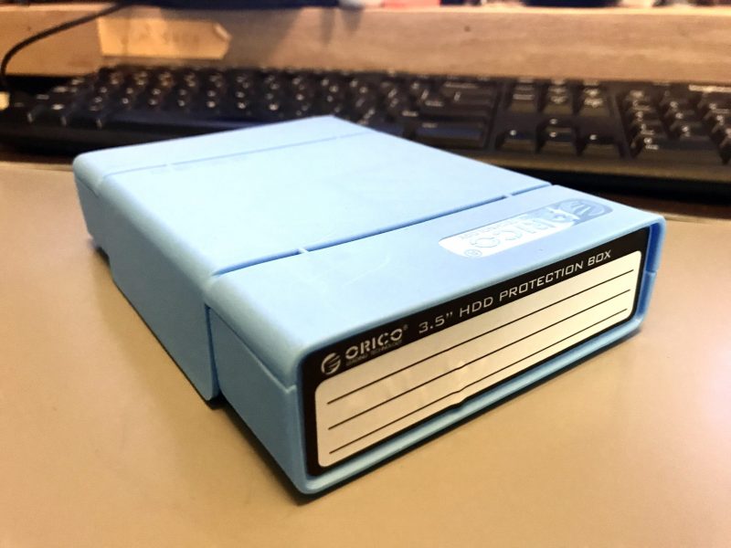
Earlier this year, Mark gave me this 8TB hard drive chock-full of spectrum recordings.
One of the joys I’ve discovered in making field spectrum recordings is sharing them with fellow DXers. Most of the time when I go to shortwave radio gatherings (like the Winter SWL Fest), I take a couple hard drives to exchange with other SDR enthusiasts. My friend, Mark Fahey, and I have exchanged some of our favorite spectrum recordings this way. I give him a hard drive chock-full of terabytes of recordings, and he reciprocates. Back home (or on the train or airplane) I open one of his recordings and, boom! there I am in his shack in Freeman’s Reach, Australia, tuning through Pacific stations that are not easily heard here in North America, maybe even turning up some gems Mark himself may have overlooked…just as he is doing with my recordings from the southeast US.
I’ve also acquired DXpedition spectrum recordings this way. It’s great fun to “be there” through the recordings and to enjoy some of the benefits of being on the DXpedition in times when I couldn’t actually make it there in person. For a DXer with a consuming job, busy family life, or maybe health problems that limit their travel, an SDR recording is the way to go.
Good Reason #5: Family time

Photo by David Straight
I’m a husband and father, and no matter how much I like to play radio when we’re on vacation, my family comes first, and our family activities take priority.
Having a field-portable SDR setup means that I can arrange a “set it and forget it” spectrum capture device. Before we head out the door for a family visit, tour of the area, or a hike, I simply set my SDR to record spectrum, then listen to what I “caught” after I return, or after I’m home from vacation.
This practice has allowed me to enjoy radio as much as I like, without interrupting our family adventures. Can’t beat it!
Past challenges
With all of these benefits, one might wonder why many other DXers haven’t been using portable SDRs in the field for a while now? That’s a good question.
Power
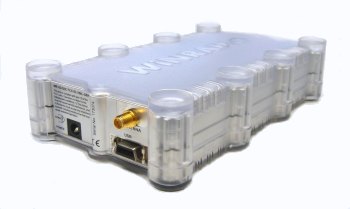
The WinRadio G31DDC, like many SDRs of the era, has separate data and power ports
In prior years, DXers and listeners might have been reluctant to lug an SDR and its requisite apparatus out with them. After all, it’s only been in the past decade or so that SDRs haven’t required a separate custom power supply; some legacy SDRs either required an odd voltage, or as with my WinRadio Excalibur, have very tight voltage tolerances.
Originally, taking an SDR to the field––especially in places without grid mains power––usually meant you also had to take a pricey pure sine wave inverter as well as a battery with enough capacity to run the SDR for hours on end.
Having spent many months in an off-grid cabin on the east coast of Prince Edward Island, Canada, I can confidently say it’s an ideal spot for DXing: I can erect large wire antennas there, it’s on salt water, and there are literally no locally-generated man-man noises to spoil my fun. Of course, anytime we go to the cottage, I record spectrum, too, as this is truly a honey of a listening spot.

The view from our off-grid cabin on PEI.
The first year I took an SDR to the cabin, I made a newbie mistake: it never dawned on me until I arrived and began to put it to use that my Goal Zero portable battery pack didn’t have a pure sine wave inverter; rather, I found it had a modified sine wave inverter built into it. The inverter could easily power my SDR, sure, but it also injected incredibly strong, unavoidable broadband noise into the mix. It rendered my whole setup absolutely useless. I gave up on the SDR on that trip.
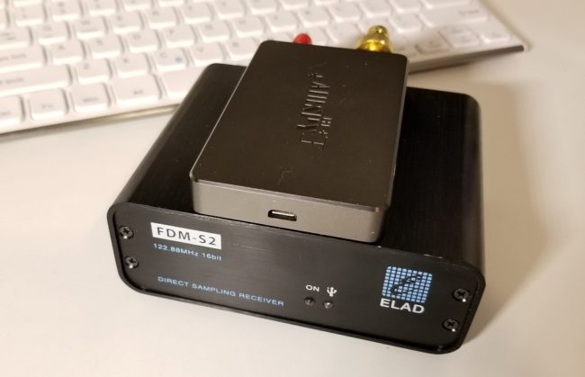
Both the Airspy HF+ (top) and FDM-S2 (bottom) use a USB connection for both data transfer and power. Photo by Guy Atkins.
Today, most SDRs actually derive their power from a computer or laptop through a USB cable, one that doubles as a data and power cable. This effectively eliminates the need for a separate power system and inverter.
Of course, your laptop or tablet will need a means of recharging in the field because the attached SDR will drain its battery a little faster. Nowadays it’s possible to find any number of portable power packs/banks and/or DC battery sources to power laptops or tablets, as long as one is cautious that the system doesn’t inject noise. This still requires a little trial and error, but it’s much easier to remedy than having two separate power sources.
Portable computers
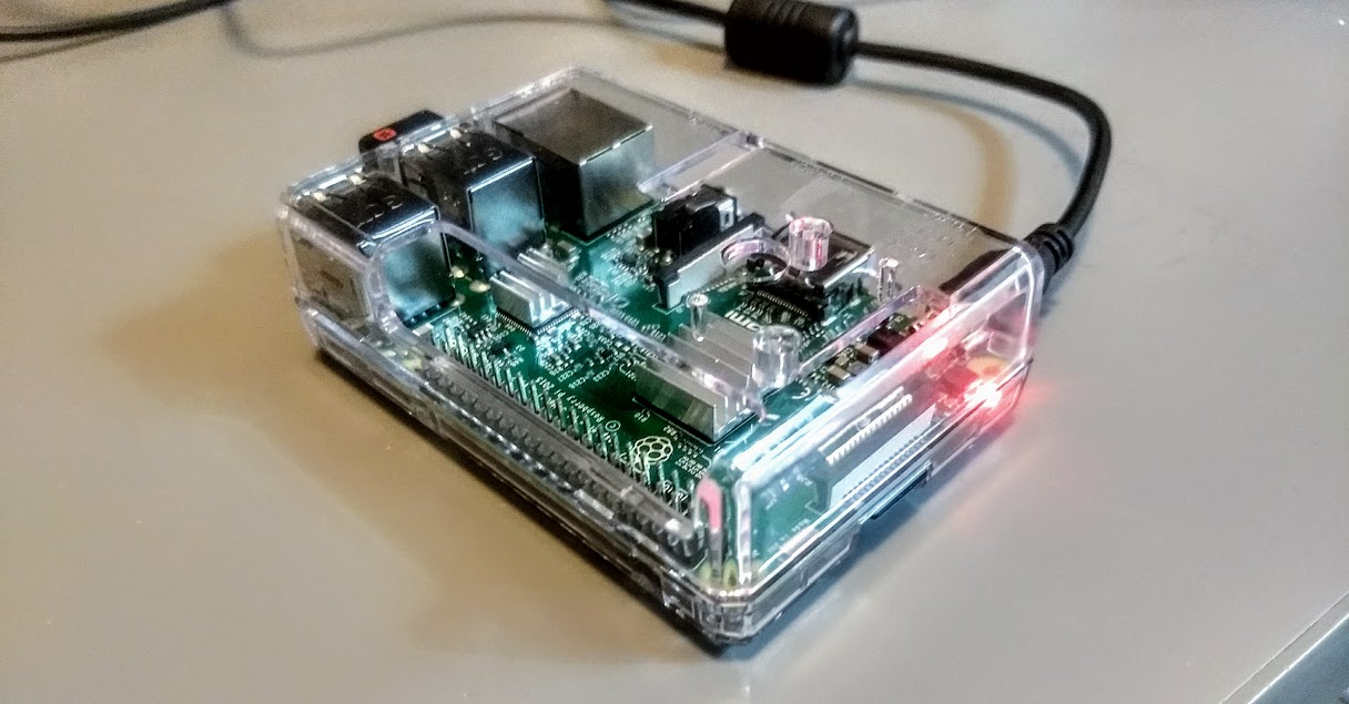
Even a Raspberry Pi 3B has enough horsepower to run SDR applications.
An SDR is nothing without a software application to run it. These applications, of course, require some type of computer.
I the past, SDR applications needed some computing horsepower, not necessarily to run the application itself, but to make spectrum recordings. In addition, they often required extra on-board storage space to make these recordings sufficiently long to be useful. This almost always meant lugging a full-sized laptop to the field, or else investing in a very pricey tablet with a hefty amount of internal storage to take along.
Today we’re fortunate to have a number of more portable computing devices to run SDR applications in the field: not just laptops or tablets, but mobile phones and even mini computers, like the eminently affordable $46 Raspberry Pi. While you still have to be conscious of your device’s computing horsepower, many small devices are amply equipped to do the job.
Storage
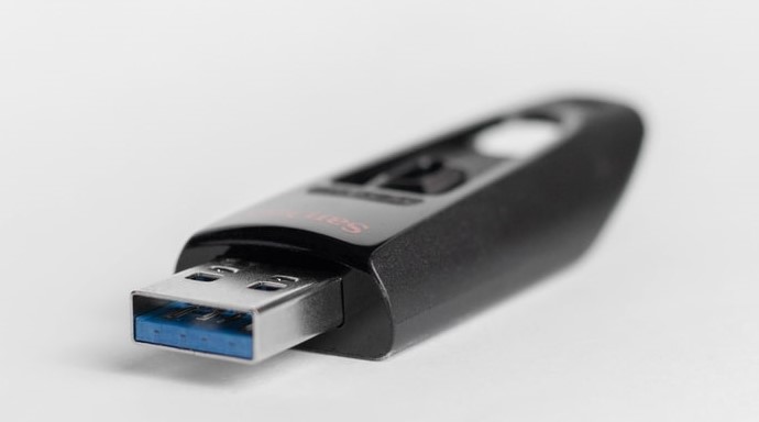
64-128 GB USB flash/thumb drives are affordable, portable storage options.
If you’re making spectrum and audio recordings in the field, you’ll need to store them somehow. Wideband spectrum recordings can use upwards of 2GB of data per minute or two.
Fortunately, even a 64GB USB flash drive can be purchased for as little as $7-10 US. This makes for quick off-loading of spectrum recordings from a device’s internal memory.
My portable SDR setup
It wasn’t until this year that all of the pieces finally came together for me so that I could enjoy a capable (and affordable!) field-portable SDR setup. Two components, in particular, made my setup a reality overnight; here’s what made the difference.
The AirSpy HF+ Discovery
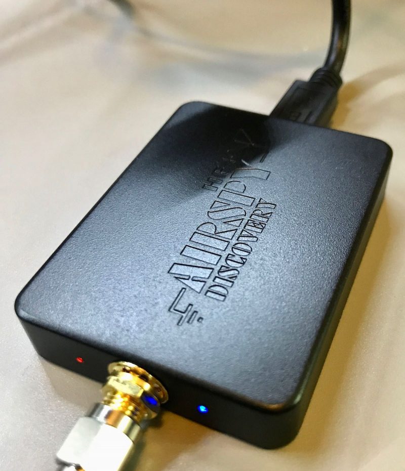
Last year, AirSpy sent me a sample of their new HF+ Discovery SDR to test and evaluate. To be fully transparent, this was at no cost to me.
I set about putting the HF+ Discovery through its paces. Very soon, I reached a conclusion: the HF+ Discovery is simply one of the best mediumwave and HF SDRs I’ve ever tested. Certainly, it’s the new benchmark for sub-$500 SDRs.
In fact, I was blown away. The diminutive HF+ Discovery even gives some of my other benchmark SDRs a proper run for their money. Performance is DX-grade and uncompromising, sporting impressive dynamic range and superb sensitivity and selectivity. The noise floor is also incredibly low. And I still can’t wrap my mind around the fact that you can purchase this SDR for just $169 US.
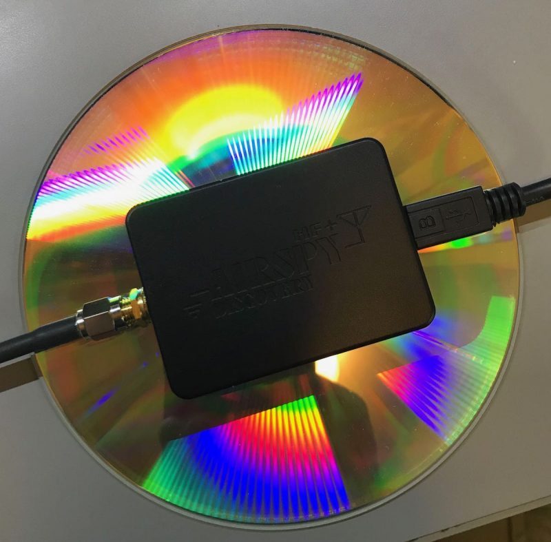
The HF+ Discovery compared in size to a DVD
In terms of portability, it’s in a class of its own. It’s tiny and incredibly lightweight. I evaluate and review SDRs all the time, but I’ve never known one that offers this performance in such a tiny package.
Are there any downsides to the HF+ Discovery? The only one I see––and it’s intentional––is that it has a smaller working bandwidth than many other similar SDRs at 768 kHz (although only recently, Airspy announced a firmware update that will increase bandwidth). Keep in mind, however, that the HF+ series SDRs were designed to prevent overload when in the presence of strong local signals. In fairness, that’s a compromise I’ll happily make.
Indeed, the HF+ Discovery maximum bandwidth isn’t a negative in my estimation unless I’m trying to grab the entire mediumwave band, all at once. For shortwave work, it’s fine because it can typically cover an entire broadcast band, allowing me to make useful spectrum recordings.
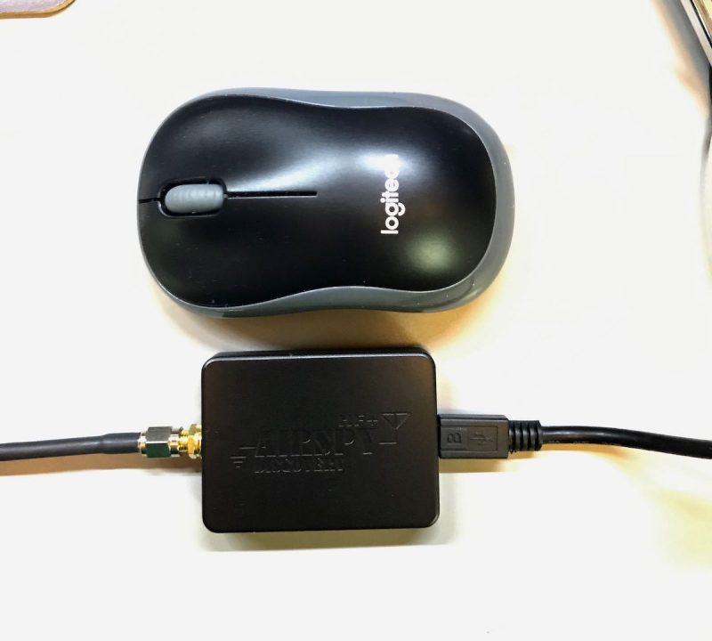
The HF+ Discovery is so remarkably tiny, that this little SDR, together with a passive loop antenna, can fit in one small travel pouch. Ideal.
The antennas
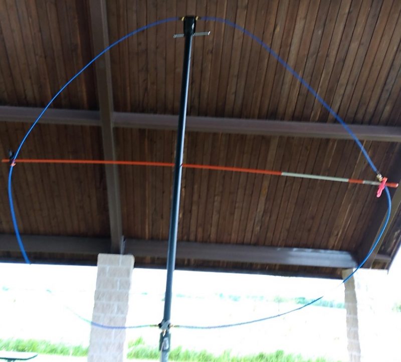
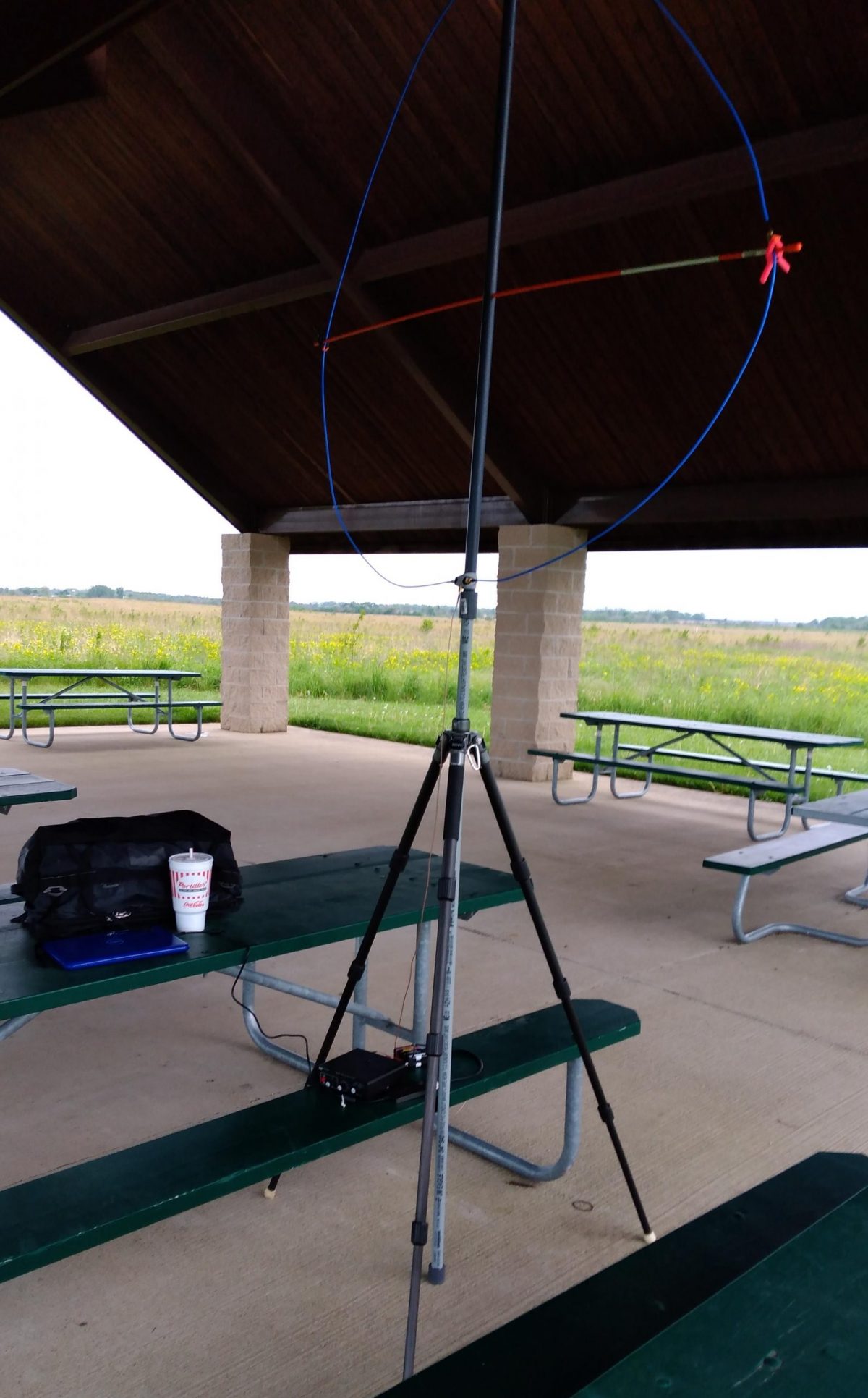
My homebrew NCPL antenna
Speaking of antennas, one of the primary reasons I’m evaluating the HF+ Discovery is because it has a very high dynamic range and can take advantage of simple antennas, in the form of passive wideband magnetic loop antennas, to achieve serious DX.
AirSpy president and engineer, Youssef Touil, experimented with several passive loop antenna designs and sizes until he found a few combinations ideally matched with the HF+ Discovery.
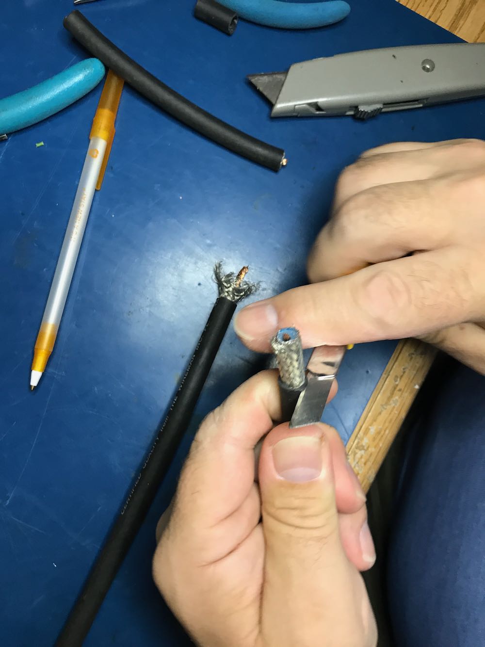
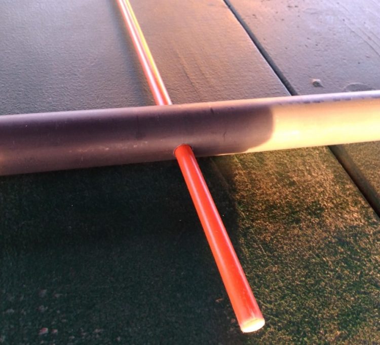
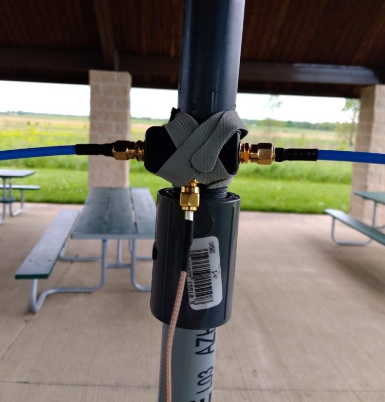
My good buddy, Vlado (N3CZ) helped me build such an antenna per Youssef’s specifications. Vlado had a length of Wireman Flexi 4XL that was ideal for this project (thanks, Vlad!). The only tricky part was penetrating the shielding and dielectric core at the bottom of the loop, then tapping into both sides of the center conductor for the balun connections. Being Vlado, he used several lengths of heat shrink tubing to make a nice, clean, snag-free design. I’ll freely admit that, had I constructed this on my own, it wouldn’t have been nearly as elegant!
Click here for a step-by-step guide to building your own NCPL (Noise-Cancelling Passive Loop Antenna.
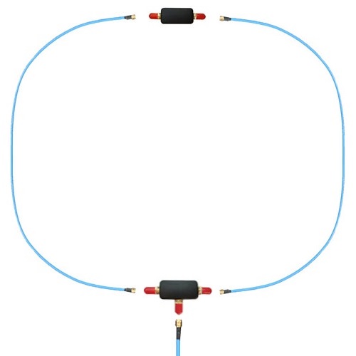
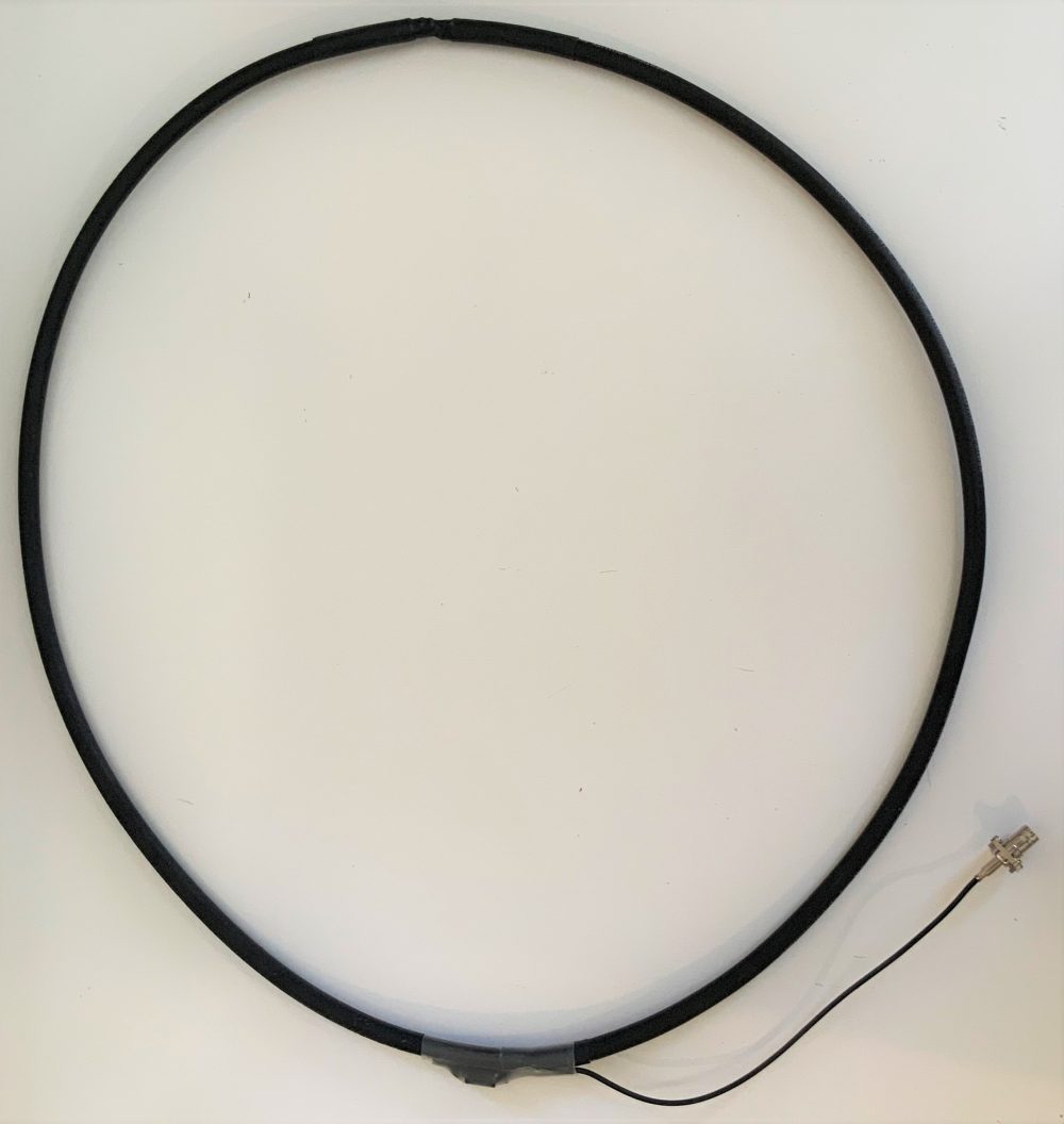
Youssef also sent me a (then) prototype Youloop passive loop antenna. It’s incredibly compact, made of high quality SMA-fitted coaxial cables. It can be set up in about 30 seconds and coiled to tuck into a jacket pocket. The AirSpy-built loop has a lower loss transformer than the one in the homemade loop, which translates into a lower noise figure for the system.
Click here to read my review of the Youloop.
Let’s face it: SDR kit simply doesn’t get more portable than this.
The computer
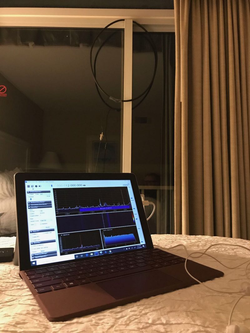
My Microsoft Surface Go tablet on a hotel bed.
In the past, I used an inexpensive, circa 2013 mini Windows laptop with an internal SSD drive. Everything worked beautifully, save the fact that it was challenging to power in the field and the internal capacity of the hard drive was so small (16GB less the operating system). In addition, it was a few years old, bought used, so the processor speed was quite slow.
This year, on the way back from the Huntsville Hamfest, I stopped by the Unclaimed Baggage Center in Scottsboro, Alabama. This center has a wide variety of used portable electronics at discount prices. I felt pretty lucky when I discovered a like-new condition Microsoft Surface Go tablet and keyboard with original charger for $190. The catch? The only data port on the tablet is a USB-C. But I grabbed a small USB-C to standard USB 3.0 dongle (for $2!) and took a risk that it would work with the HF+ Discovery.
Fortunately, it did! Score!
While the Surface Go is no powerhouse, it’s fast enough to run any of my SDRs and make spectrum recordings up to 2 MHz in width without stuttering. The only noise it seems to inject into the mix is a little RFI when I touch the trackpad on the attached keyboard.
Power
One of my LiFePo batteries
The HF+ Discovery draws power from the Surface Go tablet via the USB port. With no additional power supply, the Surface Go may only power the HF+ Discovery for perhaps an hour at most. Since I like doing fully off-grid operations and needed to avoid RFI from inverters, I needed a portable power solution.
Fortunately, the Surface Go has a dedicated power port, so I immediately ordered a DC power cable with a standard car lighter plug.
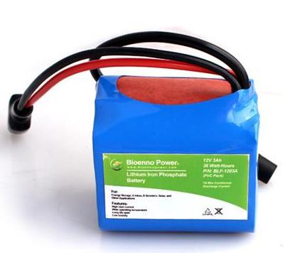
At the Huntsville Hamfest I also purchased a small 12V 4.5 Ah Bioenno LiFePo battery and paired it with a compact Powerpole distribution panel kit I purchased in May at the 2019 Dayton Hamvention.
The LiFePo battery is small, lightweight, and can power the tablet /SDR combo for hours on end. Moreover, I have noticed no extra noise injected when the DC power is applied.
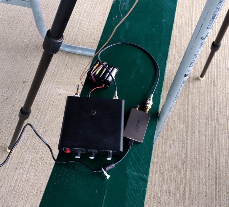
My HF+ Discovery-based portable SDR kit
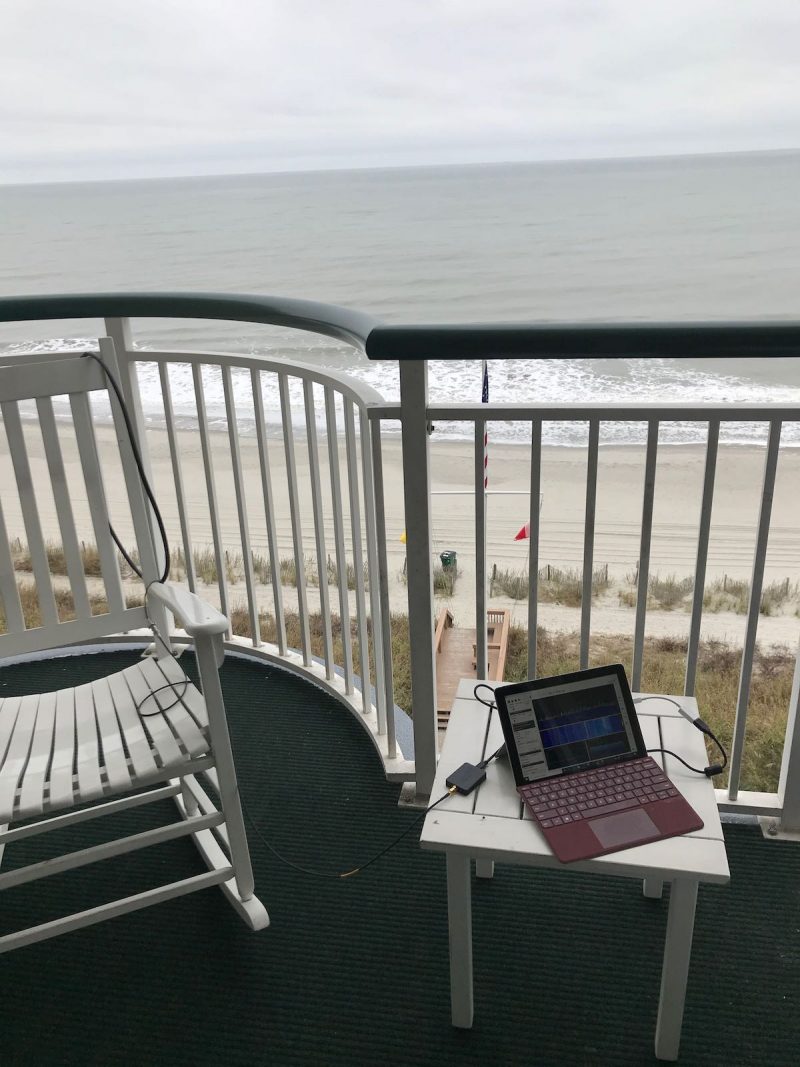
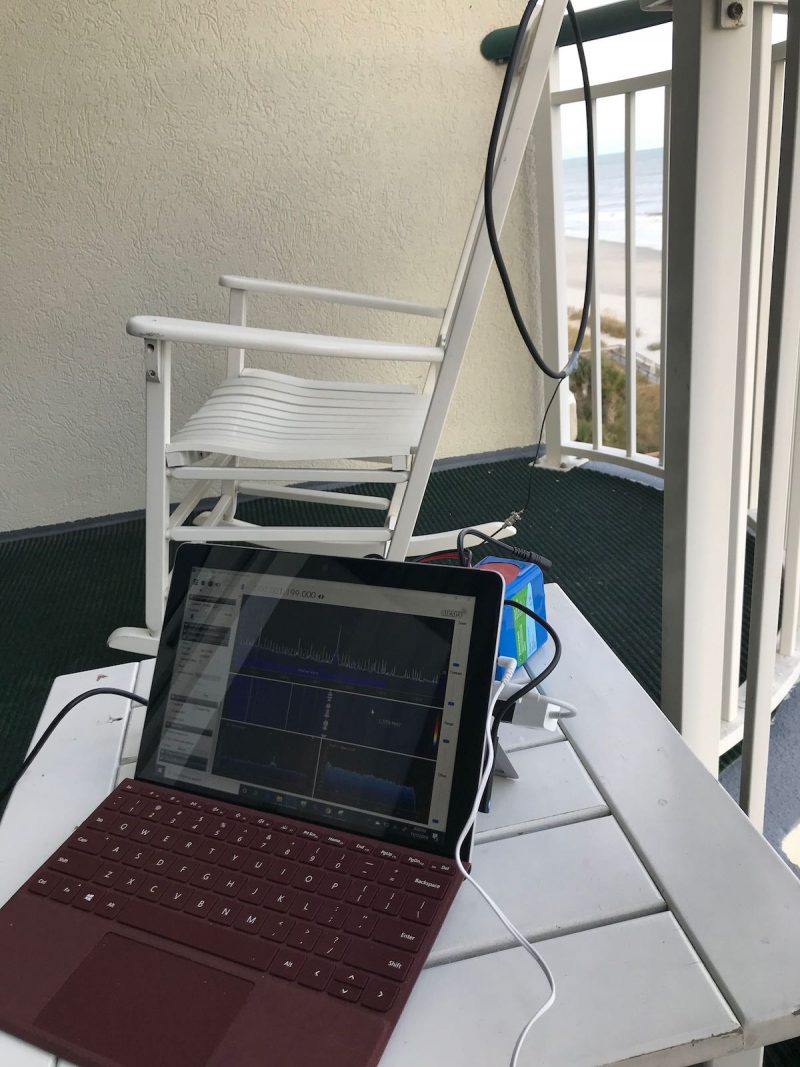
My portable SDR kit on a hotel balcony.
Now I have this kit, I couldn’t be more pleased with it. When all of the components of my SDR system are assembled, they work harmoniously. The entire ensemble is also incredibly compact: the loop antennas, SDR, Surface Go tablet, battery, and distribution panel all fit in a very small travel pack, perfect for the grab-and-go DX adventure.
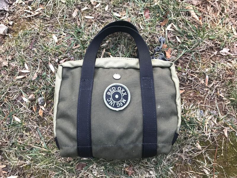
The entire kit: SDR, cables, Youloop antenna, connectors and adapters all fit in my Red Oxx Lil’ Roy pack.
In November, I took the kit to the coast of South Carolina and had a blast doing a little mediumwave DXing from our hotel balcony. We were very fortunate in that I had two excellent spots to hang the homemade loop antenna: on the main balcony, and from the mini balcony off the master bedroom. Both spots yielded excellent results.
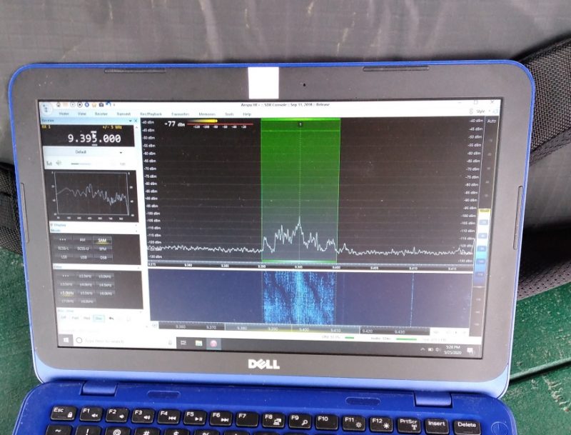
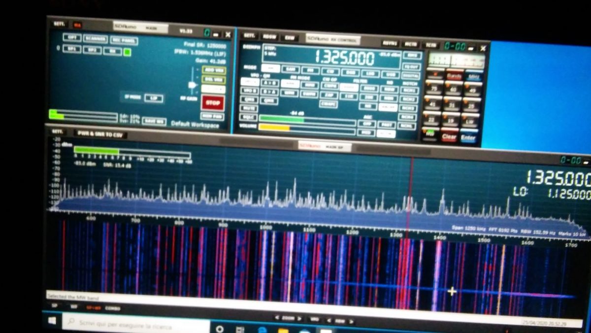
What impressed me most was the fact that the SDR# spectrum display and waterfall were absolutely chock-full of signals, and there was very little noise, even in the popular resort area where we were staying. I found that my portable radios struggled with some of the RFI emanating from the hotel, but the HF+ Discovery and passive loop combo did a much better job mitigating noise.
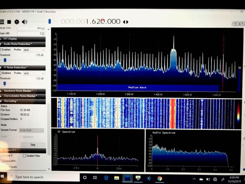
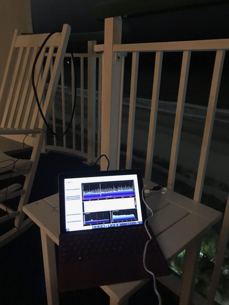
Check out the AM broadcast band on the spectrum display.
But no need to take my word for it. If you would like to experience it first hand, why not download an actual spectrum recording I made using this setup?
All you’ll need to do is:
- Download the 1.7 GB (.wav formatted) spectrum file at this address
- Download a copy of SDR# if you don’t already have an SDR application that can read AirSpy spectrum files.
- Install SDR#, and run it.
- At the top left corner of the SDR# screen, choose “IQ File (.wav)” as the source, then point it to where you downloaded the file.
- Press the play button, and experience a little radio time travel!
This particular recording was made on the mediumwave band on November 17, 2019, starting at around 01:55 UTC.
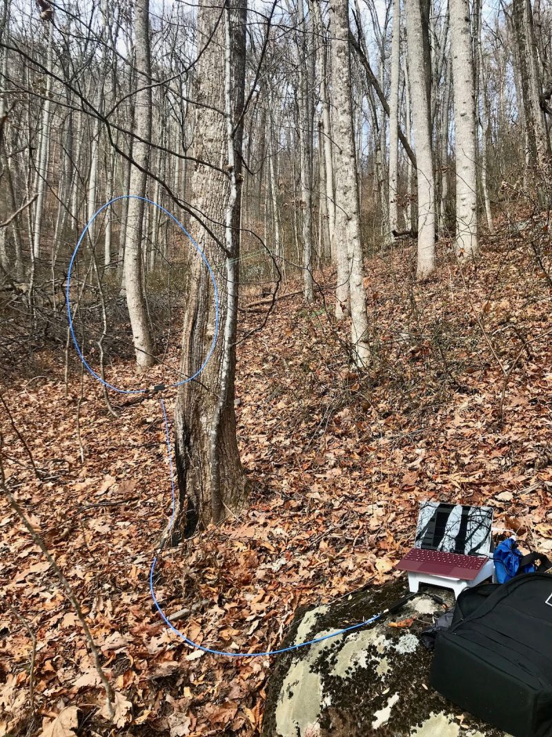
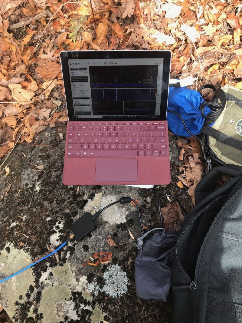
My portable SDR kit capturing spectrum during a hike in Pisgah National Forest.
I’ve also taken this setup to several parks and remote outdoor locations, and truly enjoyed the freedom of taking spectrum recordings back home to dig through the signals.
Conclusion
I finally have a portable SDR system that allows me the flexibility to make spectrum recordings while travelling. The whole setup is compact and can easily be taken in a carry-on bag when flying.
The glory of this is, I can tune through my spectrum recordings in real time and DX when I’m back home, or even on the way back home, in the car, train, or airplane. It’s simply brilliant.
If you don’t already own an SDR, I can highly recommend the AirSpy HF+ Discovery if you’re primarily interested in HF and MW DXing. If you need a wideband SDR, I could also recommend the recently released SDRplay RSPdx, although it’s slightly heavier and larger than the AirSpy.
Thankfully, I am now an SDR enthusiast that can operate in the field, and this radio has had a lot to do with it. I’ll be logging many hours and miles with the AirSpy HF+ Discovery: its incredibly compact footprint, combined with its brilliant performance, is truly a winning combo.
Click here to check out the Airspy HF+ Discovery
Related articles:
Do you enjoy the SWLing Post?
Please consider supporting us via Patreon or our Coffee Fund!
Your support makes articles like this one possible. Thank you!