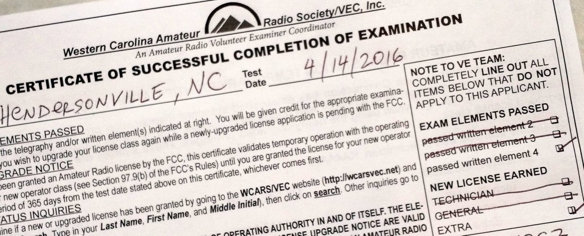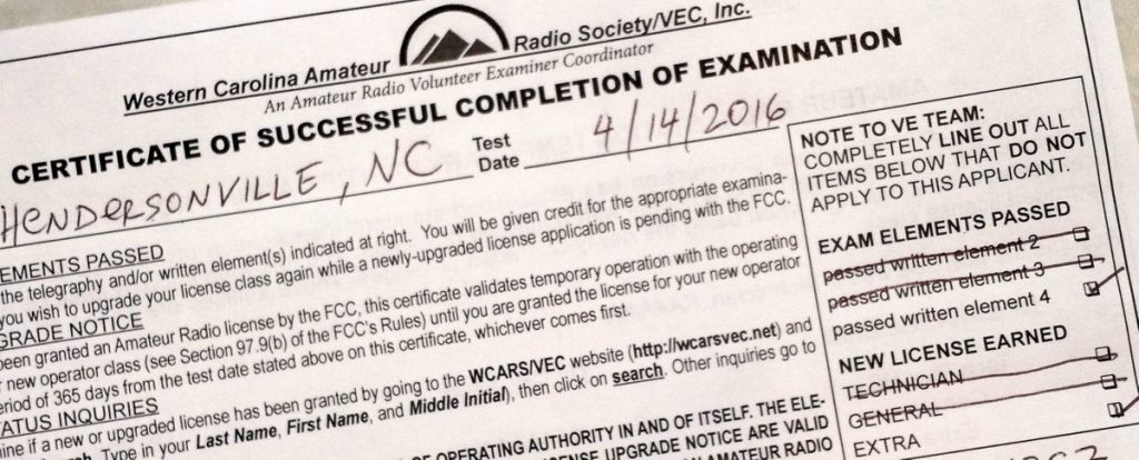
Thursday night, I passed my Extra class ham radio license exam and–woo hoo!– I’m chuffed!
The Extra class is the highest class amateur radio license you can hold in the United States. I’ve put off studying for this test for more than 17 years.
Why? Well, for one thing, I’m not an electronics engineer–indeed, I’ve never taken a formal course on electronics other than the practice study I did for my first three amateur radio licenses. The Extra exam is chock-full of formulas and electronics theory and it intimidated me for ages. Studying for it was…well…arduous.
I did, however, enjoy studying for my Technician, Novice and General exams. [Note that today there are only three license classes: Technician, General and Extra and no Morse Code requirement.] Indeed, I learned a lot about circuits and radio wave propagation from those first exams. As soon as my daughters are old enough, I’ll teach them the Technician course work.
What prompted me to study for my Extra license exam this month? I gave a presentation at the Blue Ridge Amateur Radio Club on April 4th–the president announced that the Extra class question pool was going through a major overhaul and I had already invested a few hours studying the current material.
The current Extra class question pool is only valid until the end of June 2016.
I made a decision that evening: it was time to buckle down and cram for this exam! Especially since my radio club (the NCDXCC) was giving exams the following week.
Studying
In the past, I used a combination of exam study guides published by the ARRL and W5YI, and free online practice exams provided by AA9PW. The combination worked very well.
With the Extra exam, however, I needed a method that was more persistent and one that focused on my weakest subjects.
Enter Ham Test Online

About this same time last year (April 2015), I decided to invest in an online course called Ham Test Online (HTO) with the idea that I could take the Extra exam at the 2015 Dayton Hamvention. That exam never happened because, in the build-up to the Dayton Hamvention, I had very little free time to study. Indeed, the same was true this month, but I fit study and practice time in every spare moment I had to get the exam in the books by the club meeting.
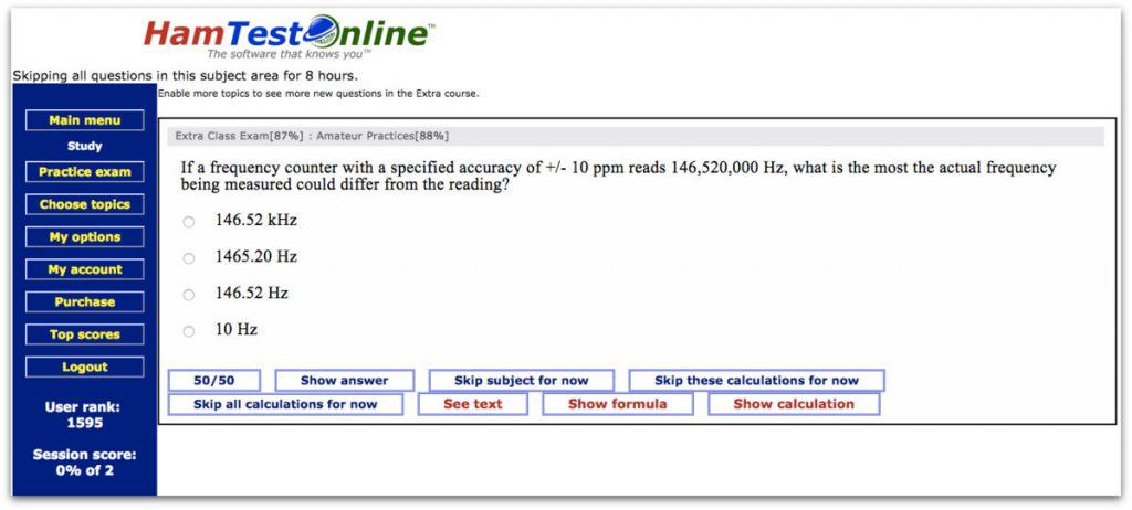
Typical Ham Test Online study screen.
According to HTO, I spent a total of roughly 30 hours studying for the Extra exam in total–at least 28 of those hours were within a one week period of time. I wouldn’t recommend this level of cramming for anyone else.
HTO advises that setting aside only one hour of study per day will have you in good shape to take the Extra exam in about one month. That is a much more reasonable timeline.
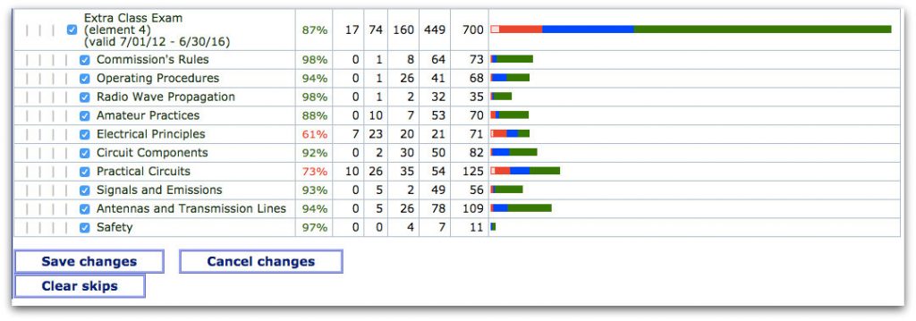
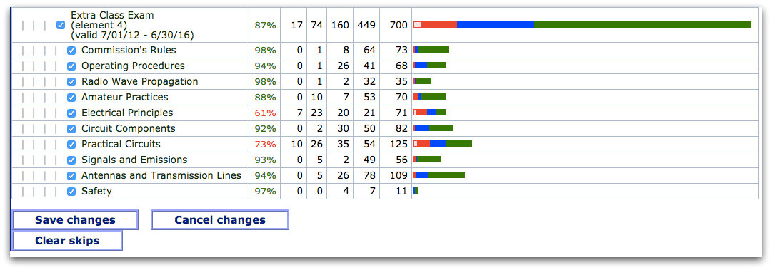
Ham Test online shows you, at a glance, your weakest/strongest subjects and topics you have yet to cover. (Click to enlarge)
In short: I am very impressed with Ham Test Online. It was worth every penny to have a dedicated tutorial system that was persistent in noting and repeating my weakest subjects.
It’s actually a very simple website and, fortunately, was usable via my Moto X smart phone’s Chrome web browser. This meant that when I was waiting for my kids in the doctor’s office or parking lot, I could study or even take a practice test without needing a PC.
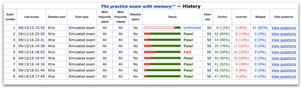
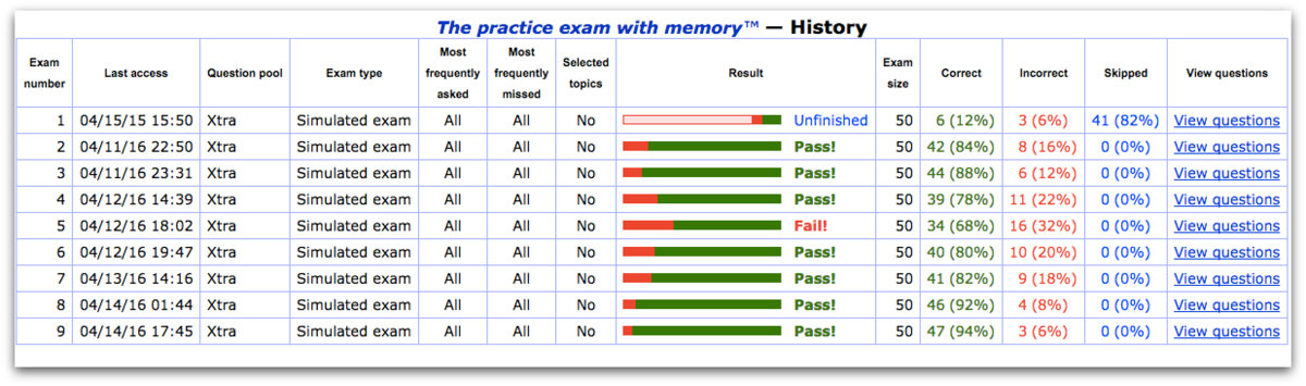
HTO keeps track of your practice exam results and notes any missed questions for review later. Keep in mind that you only need a 75% score or higher to pass the test. I felt comfortable taking the test with scores in the 85% range. (Click to enlarge)
Indeed, at any given time, I had HTO running in a web browser session on my shack PC, my MacBook, my iPad and my smart phone–they all worked in symphony, picking up the last session/topic from the device I was last using.
Summary
Here are a few notes I took while using Ham Test Online:
Pros:
- Adaptive study
- Ability to skip topics temporarily
- Informative, concise study material
- Responsive website that is even usable via smart phone
- Both the study and exam metrics show amount of material learned or committed to memory
- User has control over:
- level of persistence/repetition when a question is missed
- difficulty of practice exams
- ability to skip topics for an 8 hour period of time
- reminder emails when system hasn’t been used for study
- and more…
- Useful metrics in both study and exam modes
Cons:
To be honest, it’s hard to list many cons for HTO. I’ve never used a similar online tutorial system for comparison.
I should note that I started studying for the Extra exam last year and perhaps learned 8-10% of the total exam. After a one year hiatus, HTO never assumed I could have forgotten the material I learned last year–bad assumption! (ha ha!) Only a day before the exam, I realized I had forgotten some of the initial study material, so I forced HTO to test me on it by selecting only the first element for study. I’m glad I caught that in time. Perhaps HTO should re-check course material after an extended hiatus?
Obviously, the HTO training method works–I was able to pass my Extra Exam with only about 30 hours of total study time. I’m pretty sure I couldn’t have achieved that with books–especially on such short order–and I know of no other web-based platforms like it on the market [readers: please correct me if I’m wrong].
HTO is efficient and cost-effective–especially for those of us with an active family life. It would work well for someone who wants to learn the course material or, frankly, even for someone who is only interested in memorizing the answers.
HTO’s current price list:
- $24.95 Technician Class study course (2-year subscription)
- $29.95 General Class study course (2-year subscription)
- $34.95 Extra Class study course (2-year subscription)
(includes both the current question pool and the 2016 pool when it becomes available)
- $24.95 Renew all previously-purchased courses (for 2 more years)
If you are considering upgrading to the Extra class license, you might do so before July 2016 when the new question pool will be used. At least, for me, the deadline was a good excuse to get my act together and knock the test out!
Readers: Please comment if you’ve found other study methods or systems that have worked well for you.