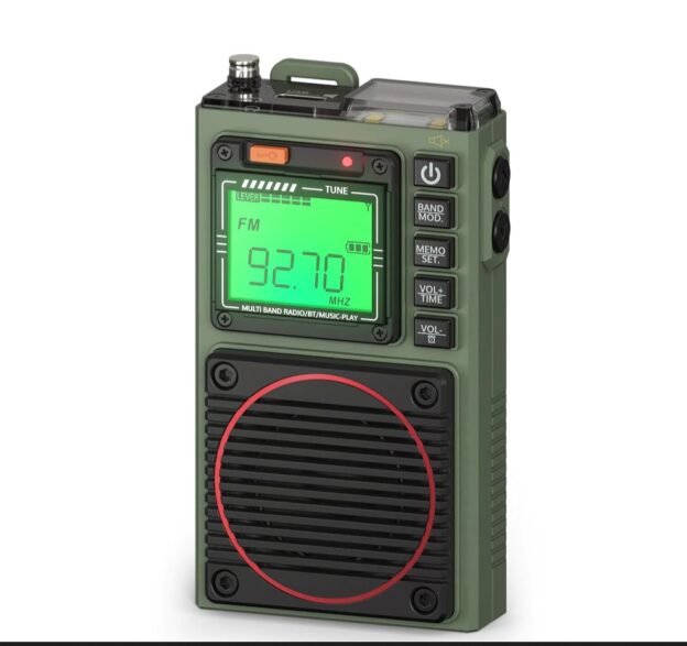
Radioddity Raddy RF75A
By Robert Gulley K4PKM
The RF75A is an interesting little radio which (currently) retails on Amazon for ~$53.00 in the States. It can also be purchased via Radioddity directly for $53–if you use this referral code, you can save $15 off a $65 purchase.
Before we get into specifics, two things are worth mentioning right off:
- I was asked if I would be interested in reviewing this radio by our fearless shortwave listening leader, Thomas, and the copy I have was provided to me at no cost by Radioddity directly. (I have no other affiliation with them, but have recently purchased a GMRS mobile radio from them which I am looking forward to using when I finish my review of the RF75A.)
- This is, as you will see from the photos I am including, a pocket radio, not to be confused with a tabletop radio or a small portable radio such as the CCRadio Skywave or similar radio. I mention this because invariably there will be folks who expect tabletop or portable quality from a radio about the size of a playing card. It is not going to happen!
Having those thoughts out of the way, the quick and dirty answer as to the quality of the radio is, I am impressed. For those who have not read anything related to my past experience with radios, I have been a shortwave listener since I was about 10 years old, and now in my early sixties. So, I have seen a fair number of radios in my time (speaking as an old codger, or is that curmudgeon?) and have even moved with the times to incorporate SDRs into my radio arsenal.
Each style of radio has its place, and a pocket radio is designed to be the ultimate in portability and space savings. As light as this shirt pocket radio is, it still manages to feel reasonably solid, and of course, it could be packed into anything one was taking along for a trip.
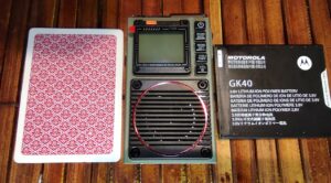
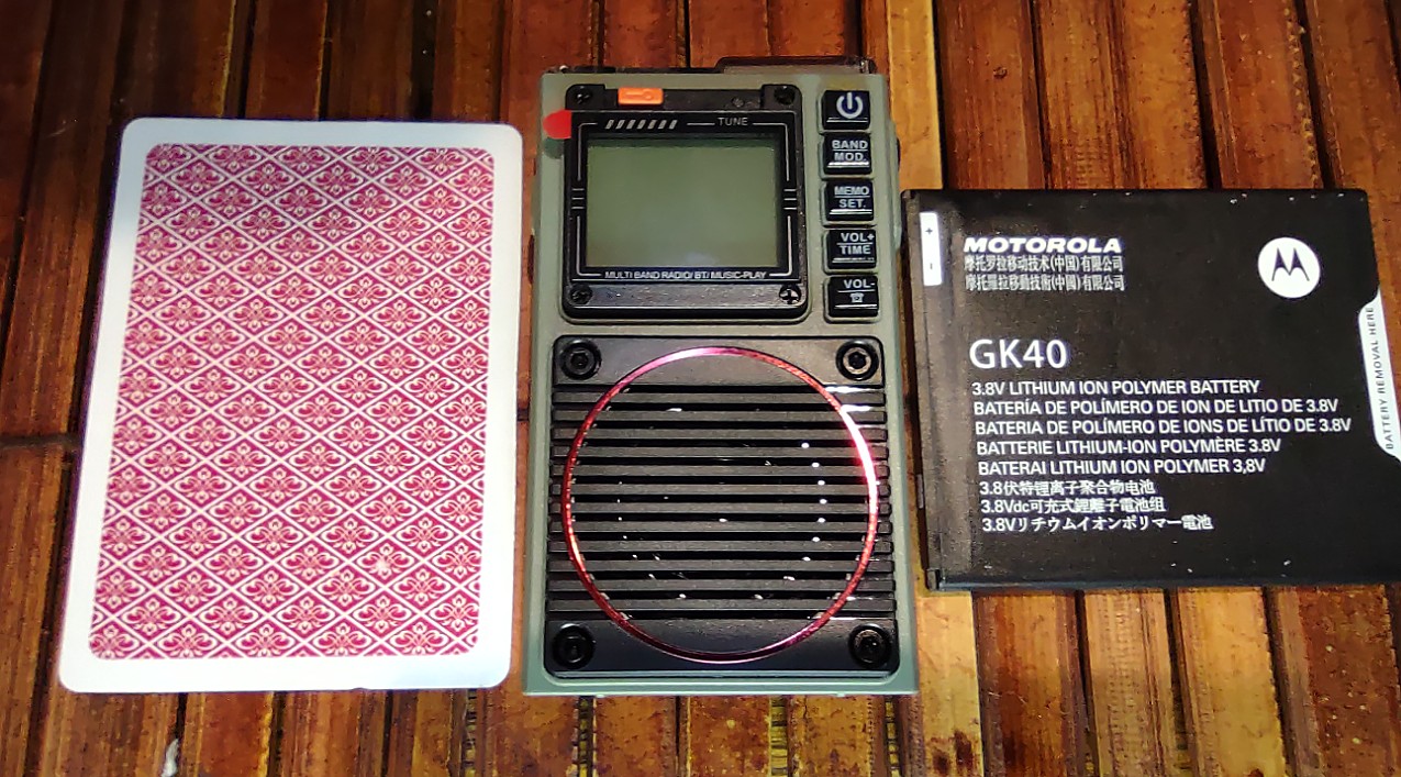
The radio measures 2.5″ x 3.5″ x 1″. Playing card and cell phone battery for comparison.
Here are some specs from the manufacturer’s website (saving you my long-winded descriptions!):
- APP Control SW Radio: Thanks to the app intelligent remote control and Bluetooth 5.0 features, you can enjoy the convenience of RF75A. With its intuitive user interface and powerful wireless capabilities, you can easily control your radio from your devices (support iOS, Android, and HarmonyOS systems).
- Wider Reception Range: Listen to FM, VHF, AM, SW, and WB, and stay up-to-date with your favorite radio shows and music with this powerful multi-band receiver. RF75A has a wider range of shortwave frequencies compared to the RF750.
- Automatic Scan and Manual Storage: You can save up to 396 stations, so you can easily access your favorite stations. Experience powerful sound and crystal-clear reception with its 9.85′ wire antenna.
- Personal Music Player: Boost your music experience with this all-in-one outdoor audio system. With Bluetooth 5.0 feature, a 3.5mm earphone socket, and a TF card socket, you can easily connect to your personal audio devices and connect to your computer as a speaker.
- Outdoor Companion: This one-of-a-kind radio is designed to be small and lightweight, making it ideal for travel and outdoor activities. Use the flashlight and SOS for emergencies.
What’s in the box?
- 1 x Raddy RF75A
- 1 x Storage bag
- 1 x Lanyard
- 1 x Wire antenna
- 1 x Type-C charging cable
- 1 x Earphone
Reception
I always like to start a radio review by either listening to AM stations first, or WWV time stations for checking out shortwave reception. In this instance I started listening to AM stations in the daytime to see what I could hear on a typical day (no storms nearby, early spring, etc.).
Living in a fairly remote area I was surprised it captured as many stations as it did, making me think the ferrite bar inside must designed well for such a small radio. Evening and nighttime listening brought in many of the usual stations with which we are familiar, particularly the so-called Clear Channel stations. What was more impressive were the many small stations I was able to pick up, not only at night, but early in the morning around 8 a.m.
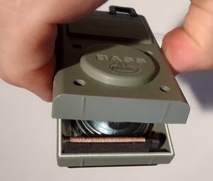
Surprisingly effective Ferrite Bar

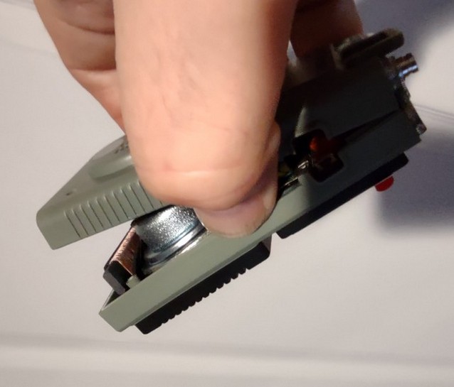
Side vide showing the magnetic wire wrap
One in particular caught my attention as I am quite certain I have never captured them before, was WHKY 1290, Hickory North Carolina. That’s a distance of about 285 miles, received in the morning. I am only about 50 miles from Cincinnati and cannot receive some of their smaller stations on any radio! Color me impressed!
Nighttime brought stations in from several thousand miles, as you would expect, yet I was likewise impressed with this little radio’s capabilities on AM.
FM
I confess to not being much of an FM listener, but I did tune around the band for FM stations to test its ability to “lock on” to signals (as indicated by a tiny red light) and to pick up stations from quite a good distance away with clarity and good sound.
This might be a good time to mention the quality of sound from the small 3 Watt(!) speaker and bass boost from the back. Again, this is not my Sangean 909 X2 with a large speaker, nor my CC Radio EP, but it has rather amazing clarity and volume capability for such a small radio. I cranked the volume up quite high with no distortion, and even though the speaker is small, the bass boost seems to round out the sound quite nicely, avoiding some of tinny sounding speakers common in such a small radio.
Weather
The radio has coverage of the NOAA weather radio stations and it surprised me with being able to receive 4-5 stations, more than I have gotten with most other radios. All but one of the signals were crystal clear, with the fifth having some noise, but still quite intelligible.
Air Band
This radio includes the air band frequencies and amateur 2-meter frequencies (30.000-199.975 MHZ). I am usually able to receive some signals, but I am quite far away from any local airports or repeaters, so my main reception is from CVG, Greater Cincinnati Airport. While the radio scans the air band frequencies, like any other radio, it is best to find local frequencies you want to hear and program them into memory so you are not wasting a lot of time scanning dead air (these are country specific). Likewise amateur repeaters or GMRS, marine, or public service channels would be best used in memory channels except when scanning for new frequencies.
SWL
Shortwave listening is very respectable, with frequency ranges between 4.750-21.850 MHz (it does not have SSB capability). Tuning can be accomplished by pressing and holding one of the directional tuning keys for about 2 seconds, a long press scans faster. A single press of either directional button will move the frequency increment based on the band/mode chosen.
The radio also features something I have come to really like: a pause button which works not only in music mode, but also when receiving regular radio signals, activated by a quick press of the power button. The frequency is held while pause is active, and then releasing the pause with a second quick press of the power button resumes with all your setting still active.
When comparing this with another radio it was particularly useful instead of having to turn the volume down like most radios. This feature is also nice for answering a call or other interruption, and you resume right where you left off.
Sound Effects, TF Card, Audio in, Bluetooth Usage and other Errata
I have not covered these features as they do not impact radio reception, but I mention them just for completeness. All of these features are available and can be read about in the user’s manual. I will mention the flashlight feature and the emergency siren features, as these are useful for portable operation. The light is quite bright, and the siren will hurt your ears if you trip it accidentally, especially more than once. Ask me how I know!
There is a sleep timer as well as an alarm clock function, with the sleep timer adjustable by default starting at 90 minutes. Most buttons have multiple functions depending on the mode employed, so reading the manual is important for some of these features. I was able to get up and running without reading the manual initially, but some features were functional only in certain modes, so eventually you will need the manual which can be downloaded from the Radioddity site.
The App
A bit of a novelty in this size and type of radio is the Apple/Android app available to control radio functions remotely through Bluetooth connectivity. I have to say, on Android at least, the app is beautiful and I wish more apps used such a clear color scheme and large controls. Your mileage may vary based on your preferences, but I like it!
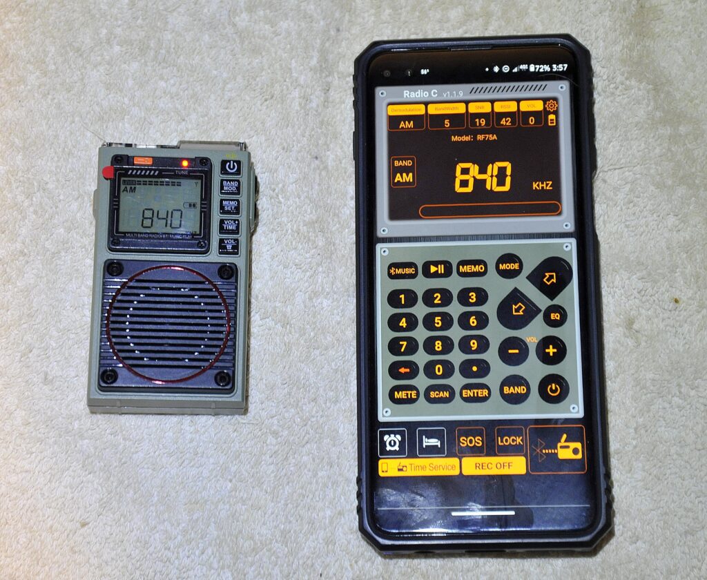
The free Phone app on an Android phone. I like the crisp, clear layout and colors, and the intuitive design.
As to function, the app gives you more information than the radio screen, such as the Bandwidth, SNR, received signal strength and the volume setting in one display. As a side note, the radio can still be adjusted at the radio, and then changes are reflected in the app almost instantaneously.
Of course, the main use for the app is to operate remotely, and the controls are easy to use, including, most importantly, direct keyboard entry of frequencies! This is always the biggest drawback to small radios without a keypad. There are instructions for using the app, but for the most part the app is laid out so well you can control the radio pretty much intuitively.
Negatives –
Yep, there are a few. When tuning with a single press each time there is some soft muting – fortunately it does not last long, but it is there. The buttons also make a clicking sound, not too loud, but it is there. If something like that annoys you, be aware all the buttons make a mechanical click.
I have noticed on several occasions that the band/mode button may stick slightly and take you past where you want to go. Not a big problem, but it does happen now and again. Of course, this could just be my unit.
Also, naturally, the buttons are small. And while I did not have much of an issue even with fairly large fingers, there were times when I pressed the desired button but also hit the one below it. Not a problem for me, but again, if you have very large fingers you may find the radio a bit tricky to navigate in some places. (This only happened on the front buttons for me, the tuning buttons are adequately spaced for most anyone I think.)
The telescoping antenna is probably the weakest point on the radio – similar to most radios, really. It is thin and could be bent easily. I had no difficulties, but I always took care to raise it gently and watched where I was moving the radio around. Then again, I do that will all my radios with telescoping antennas. Just a heads-up to be careful.
Concluding Thoughts
I like this little radio, and will probably keep it in my car for those times when I might want to listen to the radio out and about, check the NOAA weather forecast, use the flashlight, or (hopefully never need) to use the siren. The battery seems to last a long time on a charge when using the radio – I cannot speak to the MP3 drain or a prolonged flashlight/siren drain, but under normal use it seems excellent. It uses a USB-C connection like my phone, so charging is not an issue for me. It will almost fully charge in an hour; the instructions say 2 hours.
Pocket radios certainly have their niche, and I think this one does quite well in that role. If you are in the market for such a radio, I think you will be pleased, especially for the price and the addition of the free remote-control app. 73!
Click here to check out the Raddy RF75A at Radioddity.
Click here to check it out on Amazon.com (affiliate link).