Category Archives: Guest Posts

Patrizio’s simple homebrew NCPL antenna

Many thanks to SWLing Post contributor, Patrizio Cardelli, who writes:

I’m Patrizio (SWL I – 5184 /AN) from Riva del Garda, Italy.

A few days ago, I built a Noise-Cancelling Passive Loop (NCPL) antenna. I built the 1:1 balun with a couple of ferrite 175 – 285.

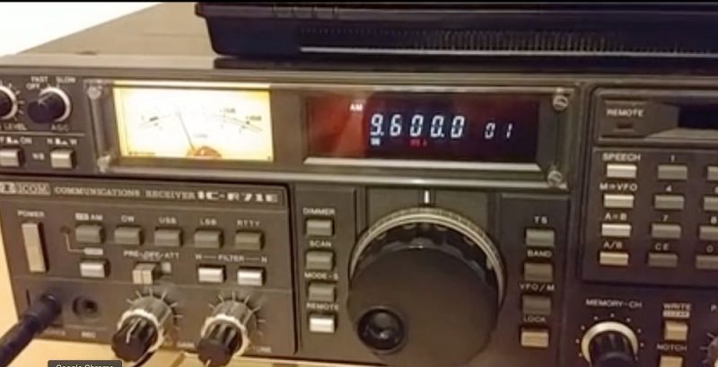
I got a good result on medium wave on my ICOM IC R 71 E with the antenna inside my house installed behind the desk just to avoid any problems with my wife.

On shortwave, the signal was low in comparison with the Bonito mini whip but in my QTH I have a lot of QRM and with this antenna I solved my problem.

Yesterday I tried the balun with my random wire (15,2 meter long) also with good results.

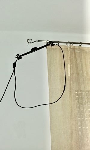
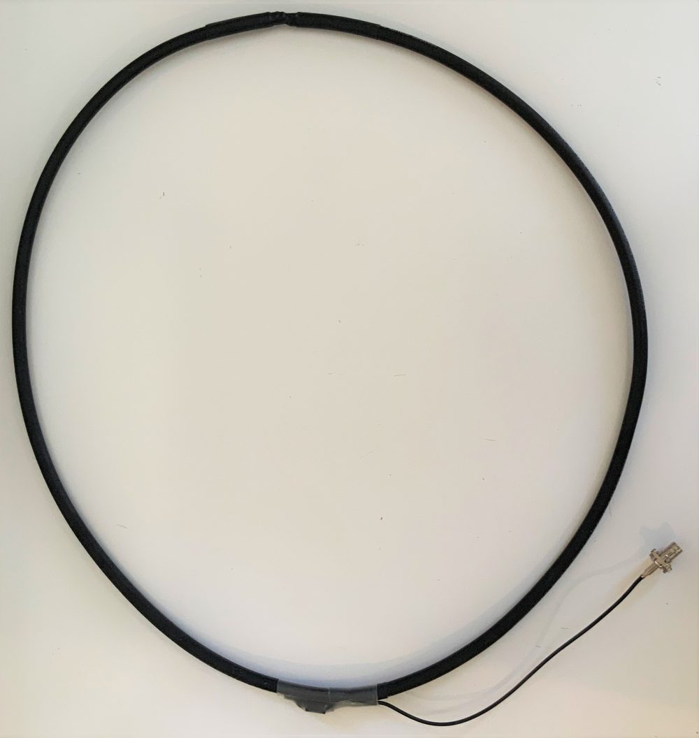
About my NCPL antenna: I made mine with RG-58 coaxial cable just to have easy portability in SOTA (please see photo) and also the feed line is made by the same coaxial cable. OK, you are right…it’s ugly:

Electrical connections are not soldered, still I don’t see any mechanical issues and this antenna since it is made for SWL / BCL purposes (meaning, RX only, no TX).

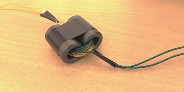
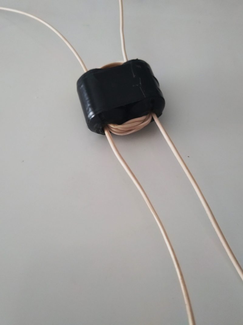
Concerning the binocular ferrite core, I didn’t have one, so I used two ferrite core type 175 – 285 (28,5 mm length, external diameter 17,5 mm and internal diameter 9,5 mm) normally used to reduce HF interference:

For the winding I used PVC insulated cable cat no: 7/0,2 type 2 (def61 – 12) conductor 7/0,2mm TSCu X 0,3mm R/T type single (4 turns primary and 4 turns secondary). It’s the same cable with which I built my random wire antenna (also portable for SOTA but now installed on my balcony until the COVID – 19 emergency is over).

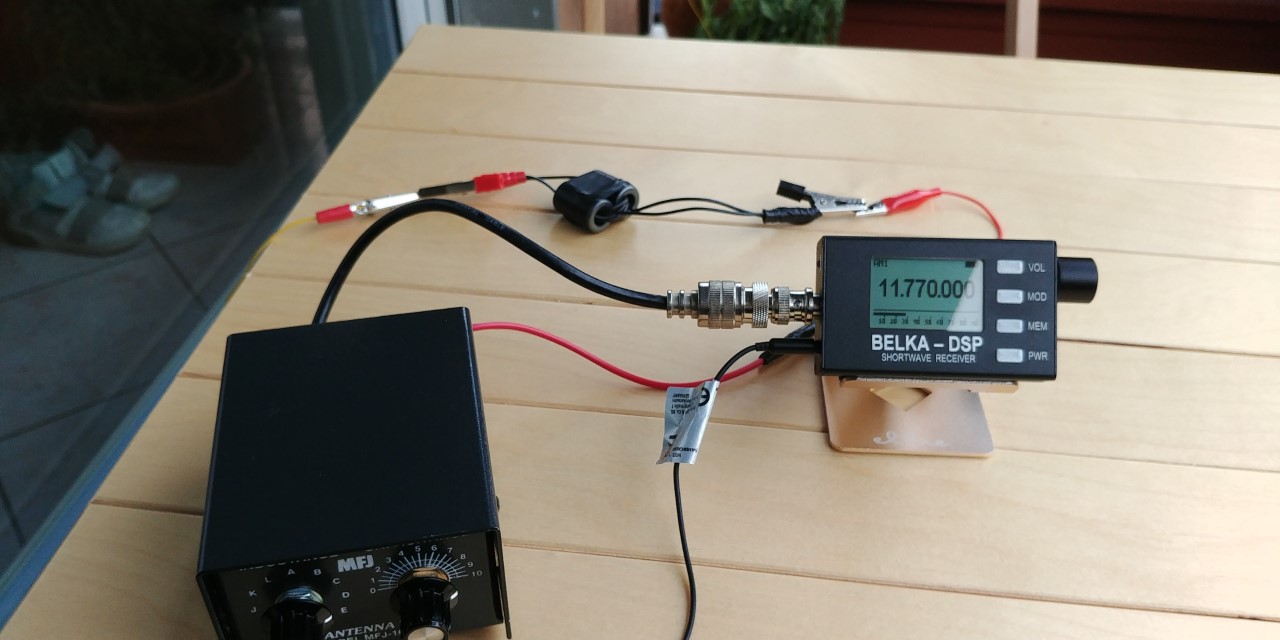
The attached videos show the situation in comparison with my BONITO MINI WHIP active antenna (also installed inside my house). Recently I changed my QTH and unfortunately here I have a lot of interference both on MW and SW. The better results that you can hear are achieved with my NCPL antenna.

I have made this test with my ICOM IC R 71 E + BHI noise cancellation speaker…..you can assess yourself, the better results that you can hear are achieved with the NCPL antenna and in the case of Tecsun PL-660 without any noise cancelling filter (BHI speaker off).

Thanks for sharing this, Patrizio! As you say, the NCPL loop seems to do a fine job helping to eliminate local RFI/QRM. The Bonito Mini Whip is a fine antenna, but not optimal for environments with a lot of radio noise–that’s where the NCPL antenna really shines.

You also make a good point that if you’re simply experimenting and only using an antenna for receiving, you can be more relaxed about the build because you’re not sending RF through it. In the end, however, properly soldered and protected connections will last much longer and provide better, more reliable performance.

Thank you, again, for sharing your build, Patriio! Those reception results speak for themselves!

Using Adobe on Android to read The Spectrum Monitor magazine

Many thanks to SWLing Post contributor, Bill Hemphill, who writes:

I was very happy to see your post about The Spectrum Monitor magazine. Like you, I am a big fan of it and have subscribed for several years and have purchased the archived years.

Usually, I am not a fan of digital magazines. They either are in special formats requiring special programs or even special versions of Acrobat. Like you, I was happy to see that it is in standard PDF format.

But that still brought up a problem. With my eyesight, I need to zoom in on the page to read it, even when using a 10” tablet and definitely if using a smaller screen such as my phone. Normally it means panning around the page, reading column one down and then going back to the top of the page to read the second or third column.

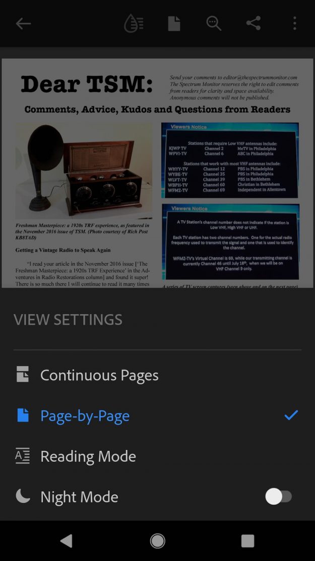
But there is some good news that many people may not be aware of. The Acrobat Reader app on the Android system allows for a mode called “Reading Mode”. What reading mode does is stack the columns up into a single column thus allowing for reading straight down – no more scrolling back to the top of the next column. And you can tap on the screen to enlarge the text and the text will reformat in a larger font to fit the margins of the screen.

I took some screen shots of TSM using Adobe Reader on my Android phone.

On the left is the complete page, on the right I have tapped on the page and while it enlarged it, I now need to scroll around to read it:

Following screen shot shows the “View Setting” Settings and “Page-by-Page” is the default setting.

What you want do is change this to “Reading Mode”:

Once you have selected “Reading Mode” you will find that the columns are now stacked vertically and you can read my just scrolling down. No more going back to the top for the next column. Also, taping on the text will enlarge it and reflow it to fit the device screen.

Left screen shot is after selecting “Reading Mode” and right is after tapping the screen to enlarge the text:

With Reading Mode, I find I can even read TSM on my Cell Phone Screen as well as my tablets.

Note: Reading Mode only works with PDF’s that have been created with this is mind. It obviously won’t work with PDF’s created from scans.

Unfortunately, while there is a “Read Mode” in Acrobat Reader DC for Windows, it does not stack the columns like the Android version does. I’m not sure if the Acrobat Reader for iPhone works the same way as Android.

Hope this is of help to others.

73
Bill Hemphill
WD9EQD
Smithville, NJ

Thank you so much, Bill, for sharing your tip! You make a really good point, too, that PDF publications give you the flexibility to change text size and adjust layout through Adobe Reader so that it’s quite easy to read even on a small device. I’m also a huge fan of PDF documents and wish other radio publications would consider adopting the PDF format instead of replying on proprietary readers and apps.

Click here to check out The Spectrum Monitor magazine. 

Finding local Emergency Alert Stations in the US

Many thanks to SWLing Post contributor, Mario Filippi (N2HUN), who shares the following guest post:


Emergency Alert Stations: A great source of local information

by Mario Filippi

During the pandemic a source of local information for residents in certain areas of the country can be found on Emergency Advisory Radio stations that dot the country and provide 24/7 information pertinent to a community.  Not all communities have these stations, which can be found from 1610 – 1710 kHz and operate at varying power outputs.

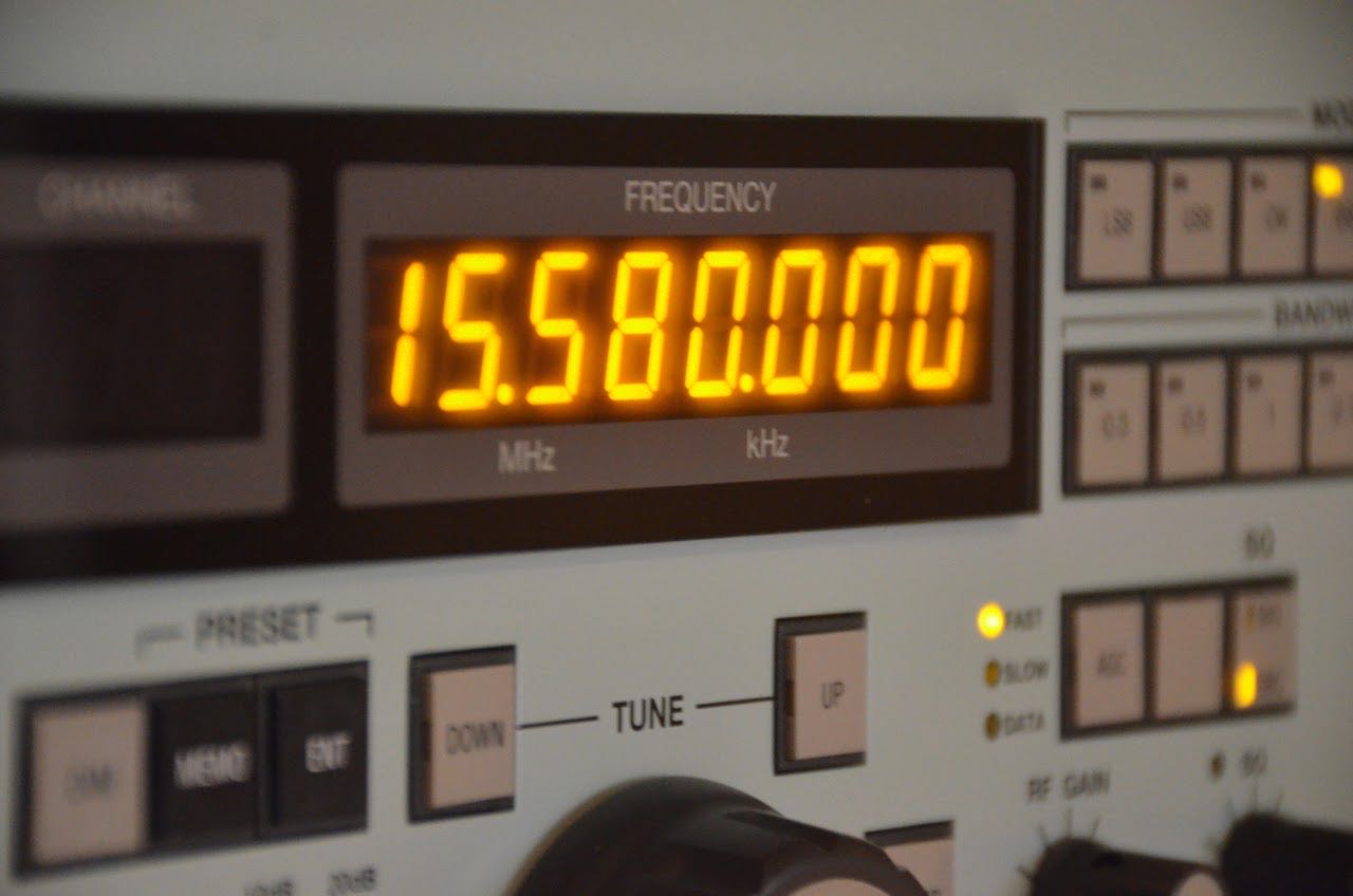
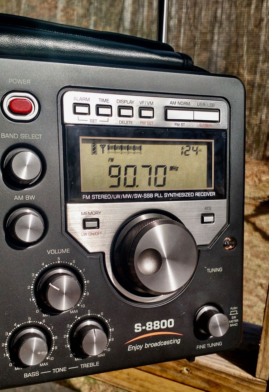
Author’s Yaesu FRG-100 tuned to EAS station

For example, a station I regularly hear is WRBX655 about 12 miles away in Franklin Township, NJ operating on 1630 kHz : https://www.franklintwpnj.org/Home/Components/News/News/6384/1130?cftype=News

At the moment it is broadcasting information on COVID-19 from the Center for Disease Control.  Every EAS  station has a call sign and wattage generally is from about 10 – 50 watts. However some stations do not necessarily announce their call signs so you can check theradiosource at: http://www.theradiosource.com/resources/stations-alert.htm

Now some of these stations are part of the HAR (Highway Advisory System) that broadcast on major roadways and usually have prominent road signs announcing where to tune your car’s AM radio for latest traffic conditions.  These stations were also termed TIS (Traveler’s Information Stations) at one time and were the precursors of HAR.  However, over the years the FCC allowed more leeway on what information could be broadcast and as a result these EAS stations appeared in communities and even state parks.

You can look up the locations of these stations to ascertain if one serves your community but the best way is to tune regularly from 1610 – 1710 kHz.  The optimal time to listen is during daylight hours as propagation changes greatly after dark and you’ll hear commercial AM radio stations coming in and overpowering most EAS.  As for range, I’ve heard HAR stations as far away as 40 miles depending on ground wave conditions which can vary greatly. QSB is common. Many of these stations will rebroadcast NWS weather information when no pertinent emergencies exist and that is another way to spot them. Some highway stations I’ve heard will begin each broadcast loop with a tone, they’re all different in their approach.

Attached [at the top of the page] is a picture of the author’s Yaesu FRG-100 tuned to WRBX655 from Franklin Township, New Jersey. For an antenna I’ve used a 31 foot vertical and a loop and success will depend on using an outdoor antenna but when away from the home QTH, I’ve heard many of these stations while traveling on the roadways of America, They’re a good break casual AM radio listening.  Give it a try.


Thank you, Mario! I must admit that when I travel, I often hunt down EAS transmitters via my car’s AM radio. Besides being a good source of local information, I do know some DXers who’ve identified and logged an impressive number of distant stations when conditions were ideal. 

If you live outside the US, do you have similar networks for local information? Please comment!

DIY: How to build a Passive Resonant Transformer-Coupled Loop Antenna for HF reception

We recently posted a tutorial on building a simple Noise-Cancelling Passive Loop (NCPL) antenna. This prompted SWLing Post contributor, Bob Colegrove, to share his excellent article on building a Passive, Resonant, Transformer-Coupled Loop (PRTCL) Antenna:


A Passive, Resonant, Transformer-Coupled Loop Antenna for Shortwave

By Bob Colegrove

Over the years I have resisted the level-of-effort necessary to construct and maintain outdoor antennas.  Rather, I have focused on squeezing out all of the microvolts I could get inside the house. Many years ago I had access to a well-stocked engineering library, and used my advantage to gather information about the theory and development of loop antennas – a daunting undertaking for an English major.  Ultimately, by adhering to a few basic rules, some of them dating back 100 years, I found quite acceptable performance can be had with an indoor passive antenna intersecting just a few square feet of electromagnetic energy.

Theory

There are a couple of advantages of resonant loops as opposed to non-resonant ones.  The first is the fact that the signal dramatically increases when you reach the point of resonance.  The second follows from the first in that resonance provides a natural bandpass which suppresses higher and lower frequencies.  This gives the receiver a head start reducing intermodulation or other spurious responses. The downside of all this is that the resonant loop is, by design, a narrow-band antenna, which must be retuned every time the receiver frequency is changed by a few kHz.  On the other hand, there is nothing quite as rewarding as the sight (S-meter) and sound you get when you peak up one of these antennas – you know when you are tuned in.

There is nothing new about the loop antenna described here.  It’s just the distillation of the information I was able to collect and apply.  There are a number of recurring points throughout the literature, one of which is the equation for “effective height” of a loop antenna.  It basically comes down to the “NA product,” where N is the number of turns in the loop and A is the area they bound. In other words, provide the coil with as much inductance as possible.  Unfortunately, for resonant loops, the maximum coil size diminishes with frequency.

With this limitation on inductance, the challenge becomes minimizing unusable capacitance in the resonant frequency formula in order to get the highest inductance-to-capacitance (L/C) ratio possible.  Some of the unusable capacitance is built into the coil itself in the form of distributed capacitance, or self-capacitance between the coil turns. This cannot be totally eliminated, but can be minimized by winding the coil as a flat spiral rather than a solenoid, and keeping the turns well separated.

The second trick is with the variable capacitor.  Even with the plates fully open, there is residual capacitance on the order of 10 to 20 picofarads which can’t be used for tuning purposes.  A simple solution is to insert a capacitor in series, about ¼ the maximum value of the variable capacitor. This effectively decreases the minimum capacity and extends the upper frequency range.  In order to restore the full operating range of the variable capacitor, the fixed capacitor can be bypassed with a ‘band switch.’ With the series capacitor shorted, the variable capacitor operates at its normal range and extends coverage to the lower frequencies.

Construction

I have constructed similar loops covering long wave, medium wave, and shortwave all the way up to about 23 MHz.  I wanted to optimize this loop for the most active portion of the shortwave spectrum. Consequently, it covers approximately 2.6 to 12.3 MHz.  See Figure 1.
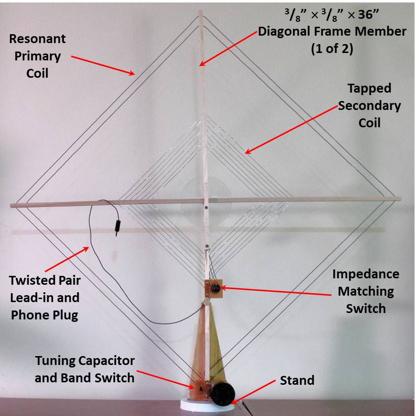
Figure 1.  A Passive, Resonant, Transformer-Coupled Loop Antenna for Shortwave

Figure 2 is a schematic diagram of the antenna.  Cd (in red) is the distributed capacitance of the primary coil, L1.  This is not tunable capacitance, but it still contributes to the resonance; likewise, the 15 pf minimum capacitance of C1.  By adding C2, the minimum total capacitance can be lowered to greatly increase the upper range of the antenna. S1 is the ‘band switch.’  It shorts out the series capacitor, restoring the maximum low frequency.
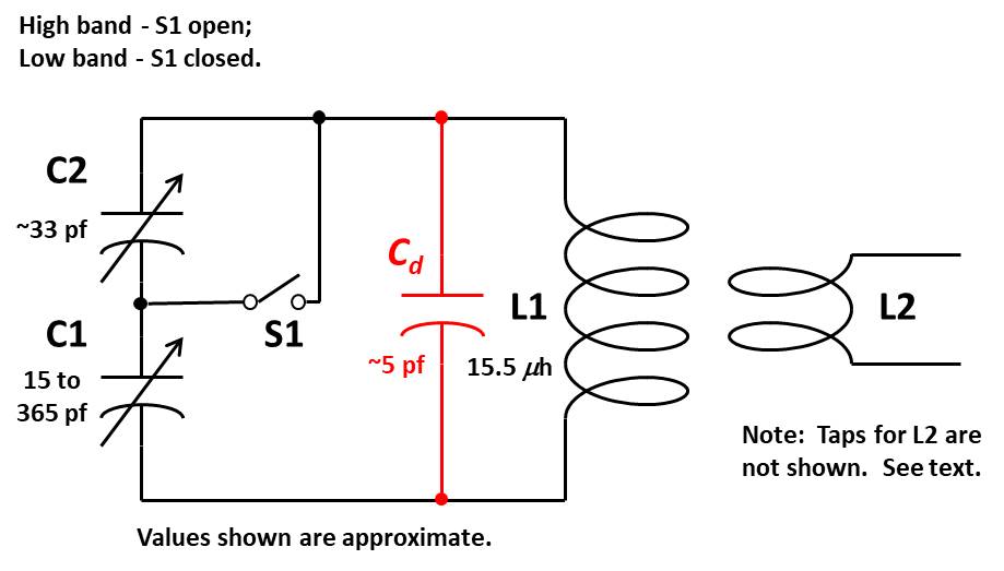
Figure 2.  Schematic Diagram

Frame – The frame is made from 3/8”-square basswood or poplar dowel (see Specialized Parts).  Two pieces, each 36” long, have been predrilled at ½” intervals to accommodate the primary and secondary coil wire (think of a tennis racket).  It is a good idea to drill holes along the length of each dowel – more than you will need. You may decide to change things later on, and drilling holes in an assembled antenna is not easy.  Also the two dowels are notched in their centers to fit together. See Figure 3 and Figure 4. The clear plastic disk in Figure 4 is a packing disk from a spindle of CDs; it is cemented to the square dowels, and used to hold them at right angles.  Any rigid, light-weight material will do.
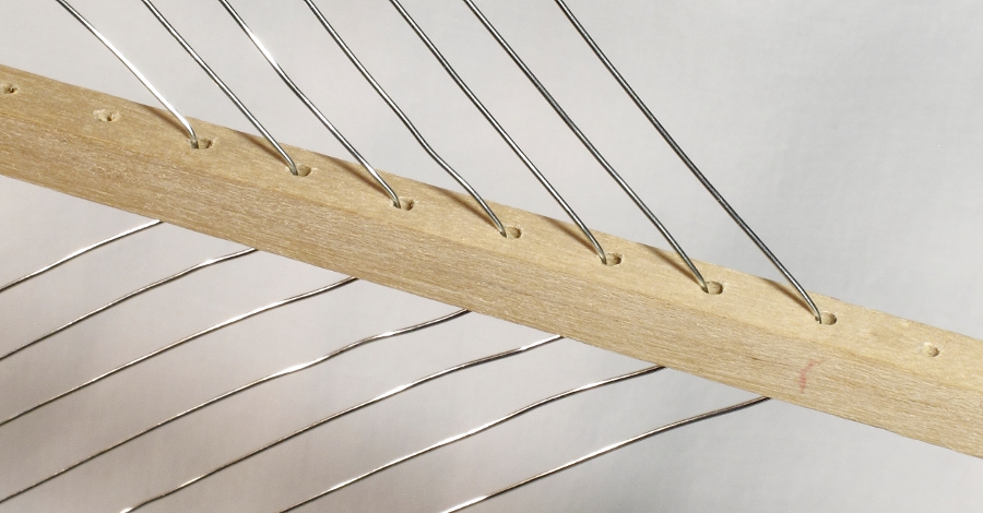
Figure 3. Square Dowel Showing 1?2” Hole Spacing and Lacing of Secondary Coil
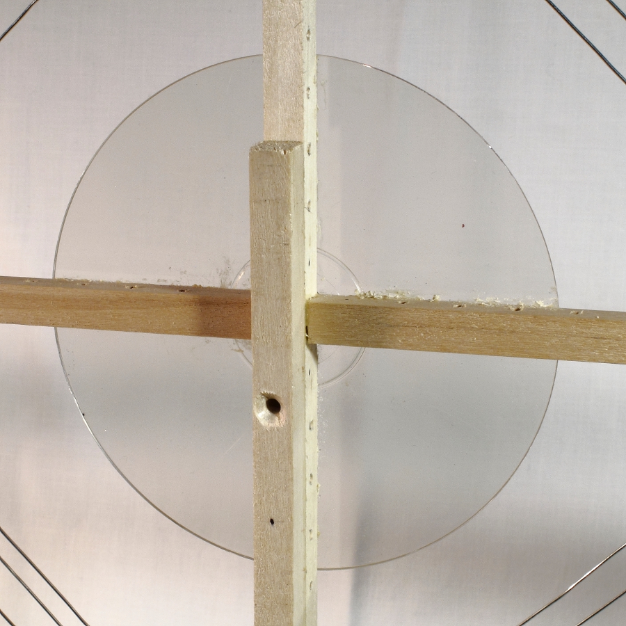

Figure 4. Cross Members Notched and Square Dowel Reinforcement

Primary Coil – With a coil size 36” in diameter, you likely won’t be able to get more than two turns of wire to resonate at frequencies up to 12 MHz.  This takes into account the precautions described above to minimize unusable capacitance.  AWG 22 stranded, insulated wire was used to lace this coil; ensure the dowels remain at right angles with one another.  Note that one set of holes in the dowel is skipped between the first and second turn.

Tuning Capacitor – Almost any salvaged variable capacitor can be made to work.  For a typical 2-gang unit, the gangs can be connected in series through the common rotor sections and metal frame with the stator terminals of each gang used as the outer terminals.  This will create a lower minimum capacitance as described above.

For the antenna described here, a single-gang, 365-pf capacitor (see Specialized Parts) was used with a fixed mica capacitor in series.  The minimum capacitance of the variable capacitor is nominally 15 pf. Figure 5 shows the capacitor assembly for the primary circuit. Components are mounted on a perforated circuit board, which, in turn, is mounted to the bottom of the vertical square dowel.  A portion of the base can be seen at the rear. A large diameter tuning knob is suggested, as the peak tuning for a properly constructed loop will be very sharp and require a delicate touch. As an option, I have used a planetary reduction mechanism on other antennas to give an 8:1 ratio with the capacitor shaft.

You may notice at high frequencies that the antenna is somewhat unstable with body contact of the knob or around the tuning capacitor.  This is because the resonant circuit is operating at a very high L/C ratio with capacitance at just a few picofarads. Body capacitance will tend to detune the antenna.  It may be useful to extend the knob 2 or 3 inches from the tuning capacitor with an insulated shaft.

Figure 5.  Capacitor Assembly

Secondary Coil – The secondary coil operates at low impedance to feed the lead-in.  There are two extremes governing the size of the secondary coil. A coil which is too small will not pick up much of the magnetic field generated by the primary circuit at resonance.  On the other hand, a secondary coil which is too large will overcouple or load the primary circuit. This will reduce the Q, or sharpness of the tuning.

The secondary coil is 16” diagonal at the largest turn and consists of 7 turns of AWG 20 buss wire.  Buss wire was used so the coil can easily be tapped after the 1st, 2nd, 3rd, 4th, and 6th turn.  The 7th turn is not currently used.  A tapped coil will provide better impedance matches to the lead-in when the antenna is used through a wide frequency range.  The taps are selected with a rotary switch. The taps are connected so that the outer turns are used first, and inner turns connected as needed.  It is important that unused turns remain unconnected (free) rather than shorted. See Figure 6.
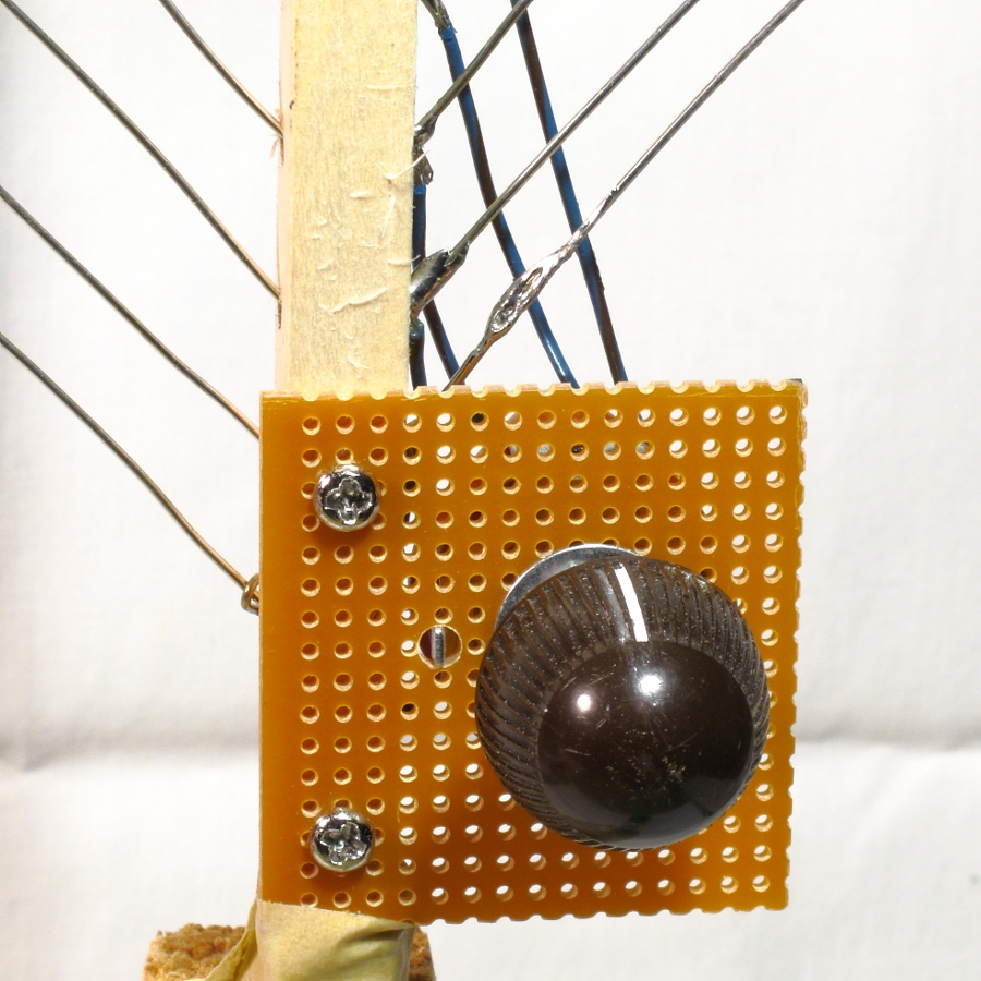
Figure 6.  Secondary Coil Switch

Lead-in – A twisted pair of AWG 22 stranded wire is used as the lead-in.  This will be more flexible than coax. The lead-in should be kept as short as possible and twisted tightly so it will not pick up any signal by itself.  This is important at shortwave frequencies. A twisted pair can be fabricated from two lengths of wire with one set of ends anchored in a vise, while the remaining ends are twisted in the chuck of a hand drill.  Most portable radios are equipped with a standard 1/8” phone jack at the external antenna connection point.  So, this antenna is terminated with a 1/8” phone plug.

Base – There is nothing special about the base.  Your only guidance should be to make it as stable as possible.  Since the frame is light, most of the weight will be at the bottom with the capacitor assembly and other parts.  That helps stability. This antenna uses a 5” plastic jar lid for the bottom. Keep the base small, as the antenna will likely be operated on a desk or table.

Operation

The antenna is intended to operate in close proximity to the radio, such as on a desk or table.  There must be sufficient space to rotate the loop laterally. As described, this antenna has a range of 2.6 MHz through 12.3 MHz with a band overlap around 8 MHz.  Depending on your selection of capacitors, your range and overlap may be slightly different.

  1. Tune the receiver to a desired frequency.
  2. Set the band switch on the antenna to the corresponding band.
  3. Tune the antenna capacitor to resonance (peak signal).
  4. Rotate the secondary switch to the position of maximum signal strength.  Begin with the fewest turns (generally one) in the secondary.
  5. It may be necessary to repeak the primary circuit.

Repeat the procedure to test operation of the upper or lower band.

Unlike similar loops for long and medium wave reception, this antenna is not especially responsive to direction for peak or null signal reception.  However, you will find it very useful to reduce or possibly eliminate locally produced noise. Simply rotate the antenna on its base.

Modification

The basic concept for this antenna can easily be extended to higher or lower frequencies.  Removal of the inner turn of the primary will significantly raise the upper frequency; whereas, adding turns will increase the lower range.  Note that the lacing of the primary coil skips one set of holes in the square dowels between the first and second turn. This minimizes distributed capacitance between turns.  This separation should be maintained if additional turns are added to lower the operational frequency.

Specialized Parts

Some sources for square wood dowel and single-gang 365 pf variable capacitors are listed below.  The author does not endorse any of them. Prices for similar capacitors vary widely.

Square wood dowel:

Variable capacitor (365 pf):


Bob, thank you so much for sharing this excellent, detailed tutorial. Although I don’t have the exact same variable capacitor, I have all of the other components to make this antenna. I will have to put this on my Social DX bucket list! Thank you again!


Do you enjoy the SWLing Post?

Please consider supporting us via Patreon or our Coffee Fund!

Your support makes articles like this one possible. Thank you!

Hack a broken VGA cable to make a binocular ferrite cores for your NCPL antenna

Many thanks to Oscar (EA3IBC) who shares this simple hack.

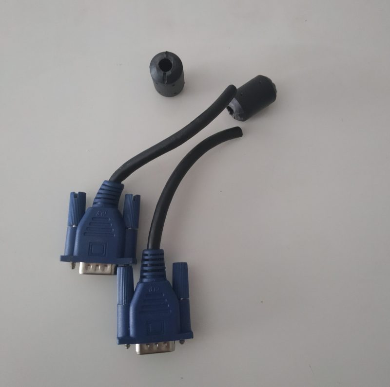
I’ve gotten quite a few emails from Post readers telling me that the only thing holding them back from building a NCPL antenna is the BN-73-302 binocular ferrite core needed for the 1:1 Balun. While so much of the world is sheltering at home due to Covid-19, it’s less convenient to purchase one just for this purpose.

But almost everyone has an old VGA or USB cable with ferrite cores they can cannibalize for this  very purpose. Oscar shared this super-simple hack on Twitter:

1. Cut the cable and remove the ferrite cores

2. Tape the two cores together

3. And wind four turns on both sides

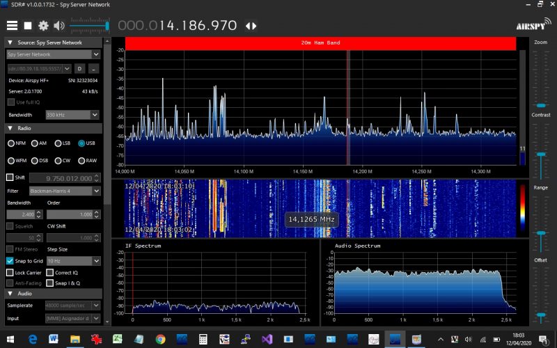
Admittedly, this 1:1 balun might not have the same properties as the BN-73-302 from our tutorial, but it seems to be working for Oscar. Check out this screenshot he shared from SDR# while hooked up to his NCPL antenna:

Thanks again!

Readers, you can follow Oscar on Twitter by clicking here.

Guest Post: “Radio. Now is your time to shine.”

Many thanks to SWLing Post contributor, Fred Waterer, who shares this message from his friend, Jarrad Brooke:


Radio. Now is your time to shine.

As more and more mass gatherings are cancelled and outdoor entertainment is cancelled – more and more people will turn to other forms of media for entertainment. Netflix and streaming are the obvious choices – but I believe even Free to Air TV and yes -radio will get a free kick as well.

I’m not talking about those in isolation or quarantine – as that is obviously an extremely small portion (or hopefully!) a small portion of our potential audience. I’m talking just the general population who feel they need somewhere to go, tune out, escape and be entertained… seeing as they have no where in groups outdoors to do it anymore.

Radio – now more than ever, needs to make sure they use this free kick of audience to their advantage to make sure they become loyal and stay. Everything that goes to air right now needs to be to the highest quality – every song, announcer break, commercial and element needs to fit now more than ever.

Radio did such a great job in the bush fire emergency. Now build on that and maximise it even more. You never know, you could be a listeners emergency today in needing them needing an escape from reality for a while.

Guest Post: Radiofreunde NRW’s DXpedition-grade signal distribution system


Many thanks to SWLing Post contributor, Joachim von Geisau (DH4JG), for the following guest post:


Signal distribution at SWL camps: The new JK-1000 HF distributor

by Joachim von Geisau (DH4JG)

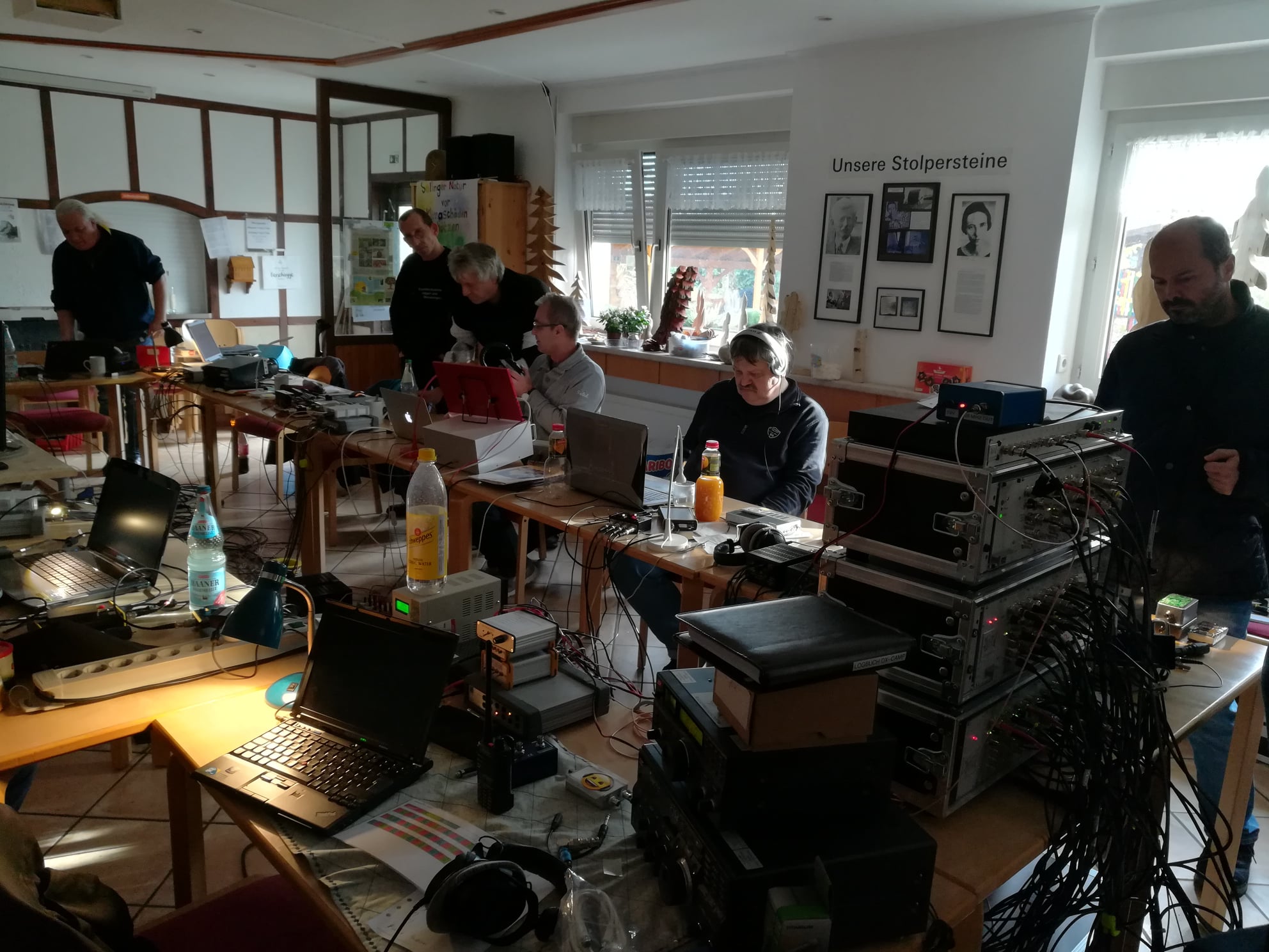
The Friends of Radio NRW – an independent group of shortwave listeners and radio amateurs in Germany – have been organizing 2-3 SWL camps per year for a number of years, where they meet as far away as possible from electrical noise in order to listen to shortwave together.

To distribute antenna signals, we have previously used an RFT AVV01 antenna distributor.

At an SWL camp there are high demands on signal distribution. Both very weak and strong signals should be distributed well, un-distorted, without noise and other interference. The signal levels are approximately between 0.2 ?V (S1) to over 5 mV (S9 + 40 dB), with a frequency range of at least from 150 kHz to 30 MHz, thus broadcast bands from LW to SW are covered, also all amateur radio bands from 160 m to 10 m.

Popular among listeners are RFT AVV01 RF distributors from the former GDR, at least 30 years old. However, the use of an AVV01 has several disadvantages: high power consumption, difficulties in getting spare parts, high upkeep with corroded contacts and the like. In addition, the transmission of the LW/MW range drops, which is a disadvantage especially for MW listeners. The NV-14 system from Rohde & Schwarz from the late 1960s has the same weaknesses.

Two years ago, the desire arose to develop a concept for the replacement of the RFT system.
The following aspects were important:

  • Frequency range at least 100 kHz – 30 MHz, as linear as possible
  • frequencies below or above desirable
  • Running on 12 V DC or integrated noise-free power supply
  • Remote power supply for active antennas
  • Robust structure
  • Versatility
  • Hobby friendly budget

The amateur radio market offers several products for RF signal distribution (e.g., ELAD, Bonito et al.), but no solution to distribute 6-8 antennas to 10-12 receivers. It was clear from the beginning that DIY development was inevitable.

The starting point of the considerations was to integrate remote power supply for active antennas, an amplifier stage and a distribution network.

Such a distributor is able to distribute an antenna signal to several receivers; several antennas require several such distributors, which led to the decision to implement the project in plug-in technology.

With OM Frank Wornast DD3ZE (www.dd3ze.de), known e.g. for his converters, filters and the like, a well-known RF developer could be won, who took over the implementation of the concept based on the detailed specifications. OM Wornast first produced a prototype without remote power supply, which already did an excellent job of RF signal distribution.

A “hardness test” at an SWL camp showed that this distribution module easily fulfilled our requirements: Frequency range 10 kHz – 50 MHz (also usable with a few dB loss above 50 MHz). Supplemented by a switchable remote power supply and a 90V gas discharger at the antenna socket, the final PCB layout was created, representing the core of the new HF distribution system of Radio Freunde NRW

The distribution block consists of the following components:

  • Input with 90V arrester & 100 kOhm MOX resistor to dissipate static interference
  • Remote power supply, switchable, 10-14 V, max. 350 mA
  • Amplifier stage with 14-14.5 dB
  • Resistor network for distribution

The device is characterized by a very smooth frequency response and has a very low inherent noise. It offers the possibility of using levels of -120dBm with very good SNR
to process up to strong levels of up to + 14dBm. In addition, the reception on VLF is now possible, which did not work with the previous system.


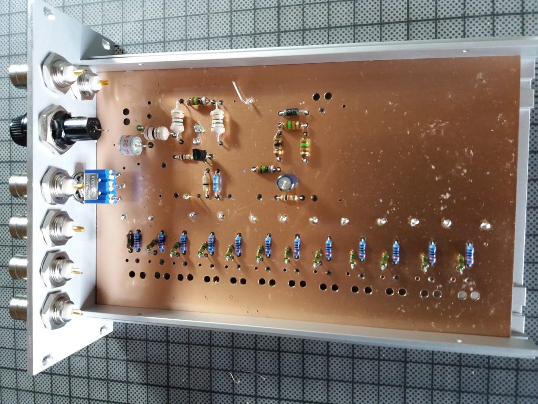
The PCB is designed in a very practical way: series resistors for LEDs are integrated as well as fixing points for coaxial cables. The remote power supply can be switched separately, but can also be used permanently by means of a jumper.

With this concept, the distribution block can be used universally: use on an active or passive antenna with distribution to several receivers, by means of a step switch in front of it also for several antennas; if you leave the remote feed path unconnected, the block can also be used as a simple distributor, so it is almost universal for hobby purposes.

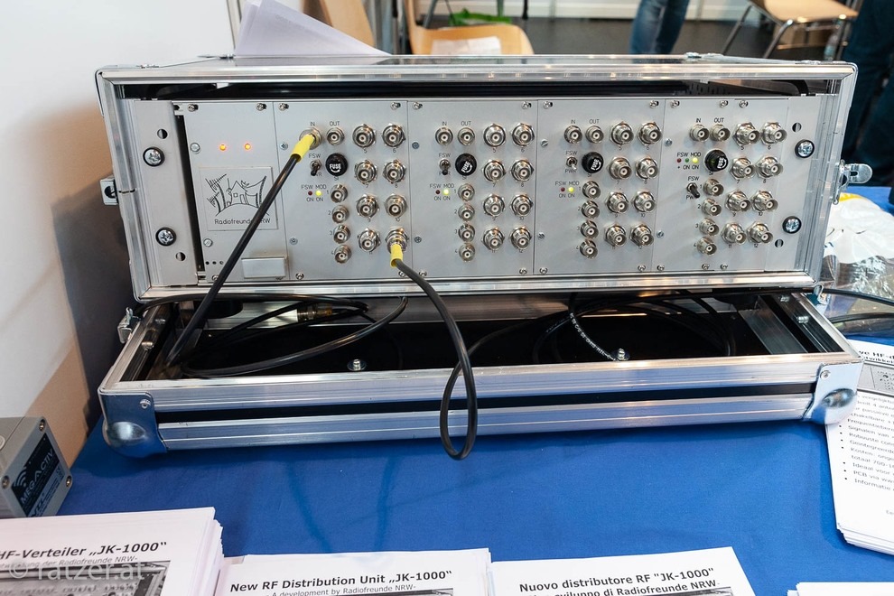
For use on SWL camps, we decided to install them in 19 “rack-mount technology. A standard rack can thus accommodate 4 distributors and a power supply, allowing  distribution of 4 antennas to 12 outputs each. An example of the installation is shown in the following picture: Parallel to the input is another BNC socket, which is connected via a C 100 nF where the input signal can be used DC-free for measurement purposes or the like. The distribution unit is installed in a transport case. The components themselves are mounted in slide-in housings which are provided with a corresponding front panel: Such front panels might be obtained from CNC manufacturers.

On the back + 12V DC must be supplied as operating voltage. For the power supply units, we opted for linear power supplies because we have made the best experience with these without interference. For a distribution unit with 4 slots, a power supply with 12V 1A is sufficient – each distribution block takes about 55 mA, an active antenna up to 150 mA, so even with “full load” a power supply with 1 A is sufficient. The distributor was tested with various well-known active and passive antennas, including a PA0RDT MiniWhip, active loops, long wires and T2FD.

Due to the wide input voltage range, the module can handle nearly any antenna. The cost for a distributor for 4 antennas amounts  (depending on the version: housing, sockets, switches, power supply, etc.) to about 700-1000 €. That may seem a lot at first glance. However, taking into account that a simple 5-gang distributor from mass production costs already around 250 ¬, the cost of the distribution of 4 antennas to each up to 12 outputs are not that much. The Friends of Radio NRW use two of these distribution units for SWL camps.

If you are interested in building one, please contact the author ([email protected]) for further information. The development history of the distribution unit is also available at www.dx-unlimited.eu.


Wow!  What a beautifully engineered antenna distribution solution, Joachim!  I love how you worked together to sort out all of the requirements for your system then build it for ultimate performance and flexibility.  No doubt, you and your colleagues at  Radiofreunde NRW posses a lot of design and engineering skills!  Simply amazing and thank you for sharing your design with the radio community!

Contact Joachim for more details and check out notes and discussion at www.dx-unlimited.eu (may require registration).