Shortwave listening and everything radio including reviews, broadcasting, ham radio, field operation, DXing, maker kits, travel, emergency gear, events, and more
The past few days, I have noticed higher than usual noise levels, generally on the lower frequencies, and particularly on the longwave band, including the 285-325 kHz DGPS band, where I run nightly SDR recordings, to later process the data and decode and detect DX DGPS stations using my Amalgamated DGPS app.
Thinking back to what new electronics devices have been added to the house, two came to mind, a new cable modem, and a new ethernet switch. The switch is up here in the shack, so it seemed to be a likely candidate. The switch is a D-Link DES-1008E 8-Port 10/100 Unmanaged Desktop Switch. It uses a mini USB port for power, using either the included AC adapter, or power from a USB port. When I installed it, I decided to not use the AC adapter, but rather a USB port on my UPS, figuring it was better to not add yet another potentially noisy switching power supply to the mix.
The test was easy, I just unplugged the power to the switch. Sure enough, the noise vanished. Great, the switch is a RFI generator. Or is it? As another test, I plugged it into a port on a USB hub. No noise. Hmm… so it seems that the noise is indeed from the USB port on the UPS. I did not notice any increase in the noise floor when I got the UPS a few months ago, but It’s something I should look into again, just to be sure. The UPS is a CyberPower CP1350PFCLCD.
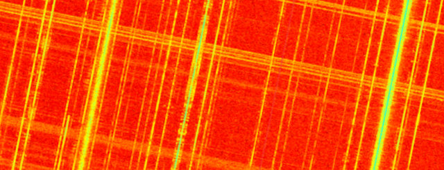
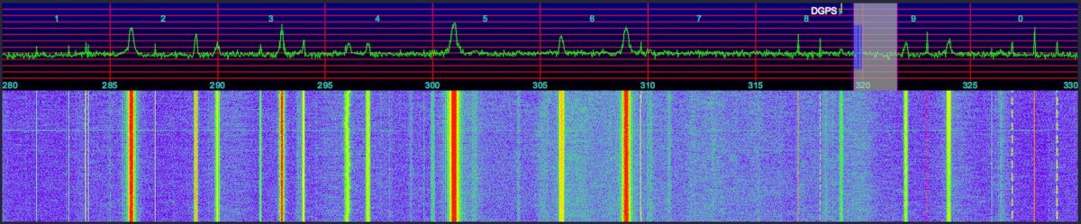
Here’s a waterfall from the SDR, showing the DGPS band, 280-330 kHz. You can see where I changed the power to the switch from the UPS USB port to the USB hub, the bottom part of the waterfall is when the switch was still powered by the UPS (click to enlarge it):
I still have a noise source just above 305 kHz to hunt down.
Update
I decided to see what I could do to improve things, and reduce the noise floor.
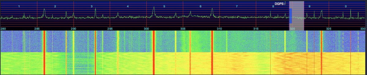
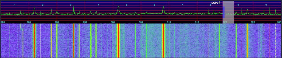
Here is the baseline, after no longer powering the switch from the UPS:
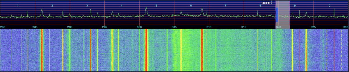
First, I relocated the AFE822 away from the computer and rats nest of assorted cables behind it, powered from an HTC USB charger:
The squiggly noise around 305 kHz vanished!
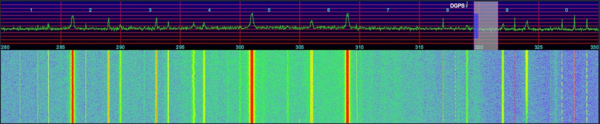
I then switched to an Apple USB charger / power supply, as their products tend to be a bit better made:
Another improvement, the overall noise floor is a bit less now.
But can we do better? I then switched to an older USB hub for power to the AFE822, that I thought might be better filtered:
I then changed to a linear supply plugged directly into the AFE822. I don’t notice any obvious improvement? Maybe it even looks like a little more noise? Difficult to tell. You can see a DGPS station popped up on 304 kHz while I was switching things around, between the last two tests, it was likely Mequon, WI.
Thank you for sharing this, Chris! I find a wideband spectrum/waterfall to be such a useful tool for tracking down sources of noise. Not only can you “see” the noise, but you can measure its bandwidth and identify what portions of the dial it affects.
Jon Hudson with SDRplay recently noted the following tutorial videos in an SDRplay discussion forum. Since I’m also trying to learn the ropes of SDRuno, I thought I’d share this here on the SWLing Post.
Jon notes:
These video guides are very helpful for newcomers to SDRuno and the RSP1 or RSP2:
RSP1: https://youtu.be/xBGHB0oMXHU
Capturing the shortwave spectrum out in the field.
Radio interference is a major problem in big cities when it comes to indoor shortwave reception. One effective solution I have found is to head for the local park and engage in scanning the bands there. However, since my time for making such outdoor trips is limited, I would always feel like I am missing out on a lot of radio action by monitoring a single frequency, which is all you can do with a standard shortwave radio. There are so many signals out there — which one should I go for? This inspired me to put together a lightweight, portable set-up that would let me capture large chunks of the shortwave radio spectrum out in the field, which I could later explore in detail. After two years of experimenting with various Software Defined Radio (SDR) technologies I am pleased to report that I finally have a solution that works well for this purpose.
A good SDR can give the user access to large portions of the radio spectrum via a graphical user interface. The user can then either process a specified part of it in realtime or record the chosen spectrum window in its entirety onto disk and analyse it later with the supplied software. Here is a short video showing the playback of one of such spectrum captures I made in a London park in September 2016. Note the final part where I zoom out to show the entire recorded frequency range (covering two broadcast bands with one ham band in the middle!):
When I got home from the park, I was able to replay that part of the spectrum capture many times over while scanning the frequency space, which is how I was able to identify a weak signal from a very distant ham radio operator that I might have otherwise missed.
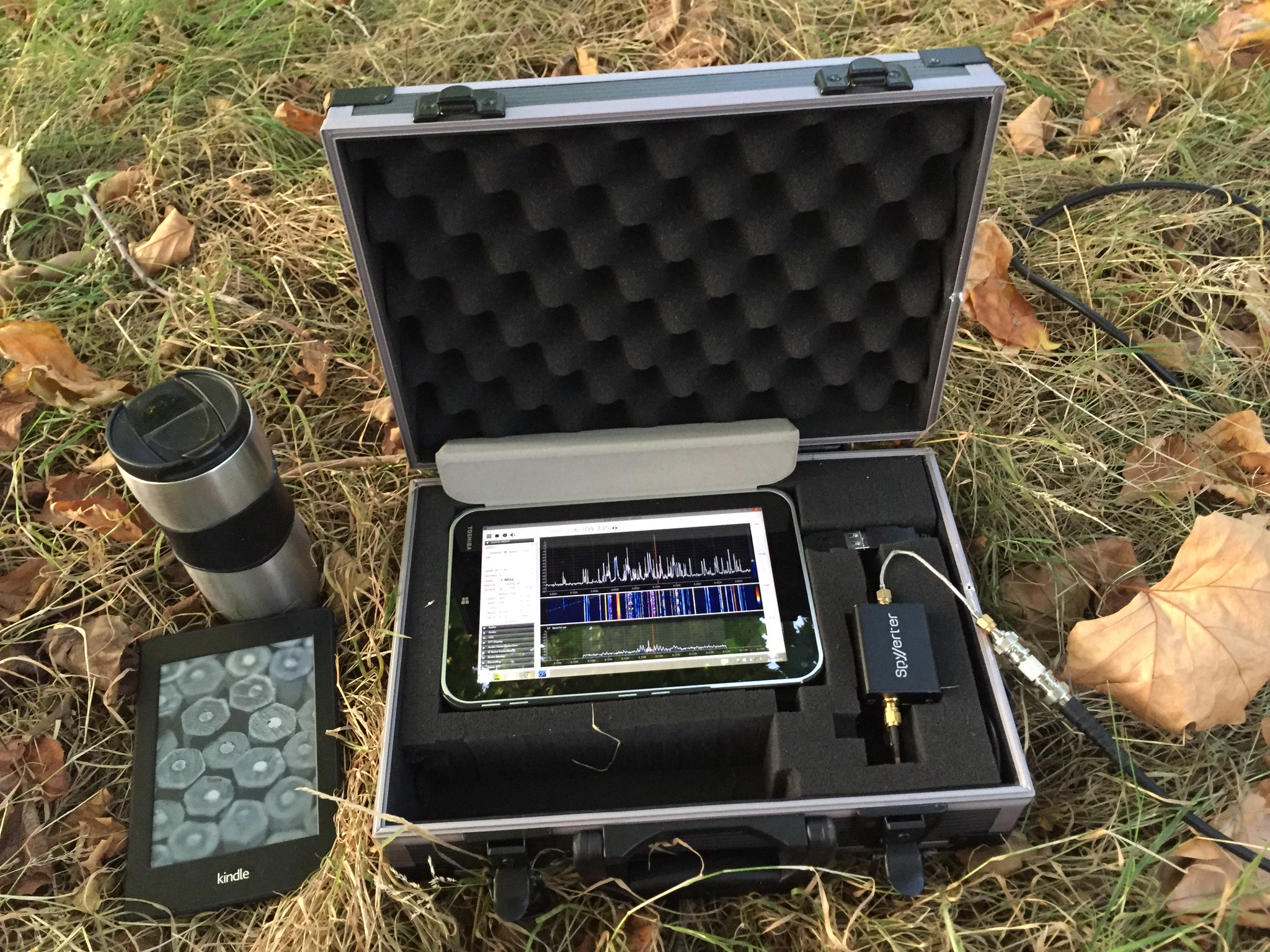
Below is the list of the components I have used to put together my “portable spectrum capture lab”.
I bought this tablet in July 2014, based on the following criteria: the device had to have a reasonably powerful Intel processor, running the Windows 8 operating system. I believe that there are currently models on the market that are at least as powerful and are substantially cheaper (<$100).
Owing to its unique hardware design, the AirSpy SDR can monitor large parts of the radio spectrum (up to 10 MHz in bandwidth) while offering a high dynamic range and robustness to overloading, with almost no mixing/imaging products.
This additional device enables AirSpy to cover the shortwave bands (in fact, the entire frequency range between 0 khz and 30 MHz) and must be connected in-line between the AirSpy’s front end and the antenna feed line, as follows:
Connection cables
Below is a small collection of cable accessories to connect the antenna to AirSpy/SpyVerter:
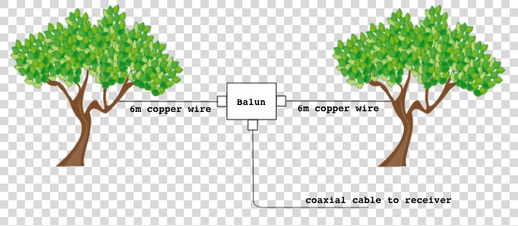
I use a three-terminal matched balun connected two 6 metre copper wires via its antenna terminals as a dipole antenna, and connect it to the SDR via the feed line terminal with the 3m BNC cable listed above. The balun (Wellbrook UMB130) is engineered in a way that prevents the radio noise current from the tablet (usually a significant source of interference) flowing into the receiving part of the antenna.
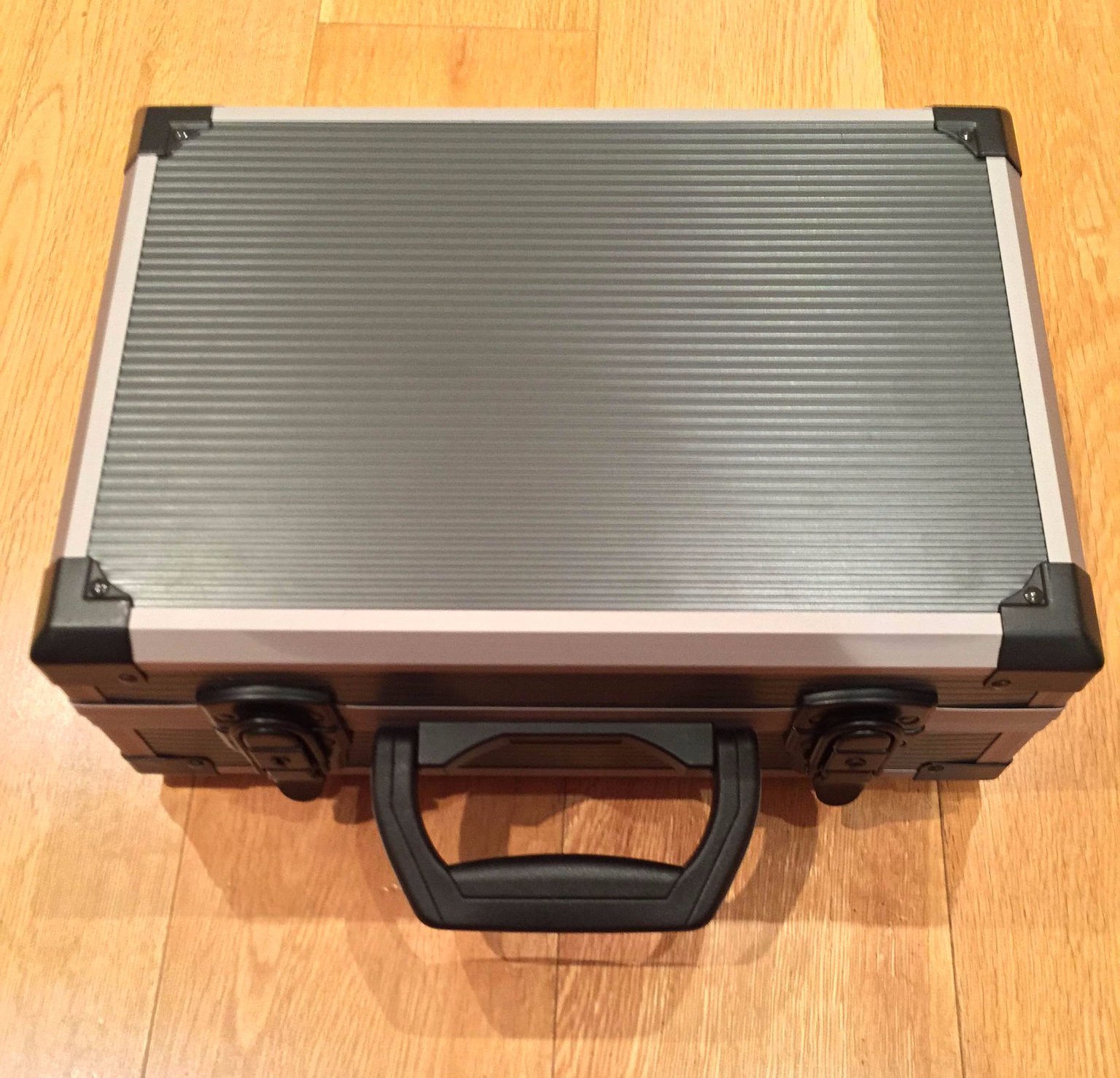
This foam-filled flight case comfortably houses all of the components. The parts 1 to 7 can remain assembled together, reducing the deployment time in the field.
I use this fast MicroSD card as the destination for my outdoor SDR recordings. The high transfer speed is critical – using slower MicroSD cards will result in large portions of the spectrum being dropped from the recordings. 64 Gigabytes can accommodate roughly one hour of spectrum data at 3 MHz bandwidth.
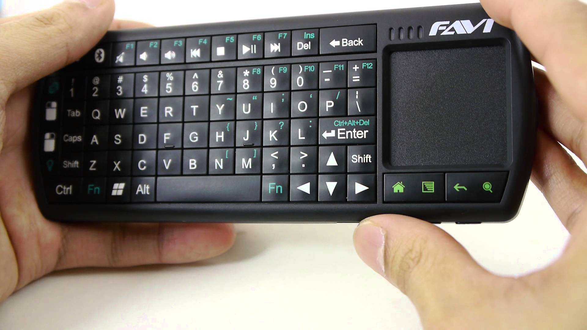
Windows tablets suffer from one major drawback: the touchscreen interface is usually inadequate for software that was designed for traditional computers with mice. A portable Bluetooth keyboard with a built-in trackpad solves this problem.
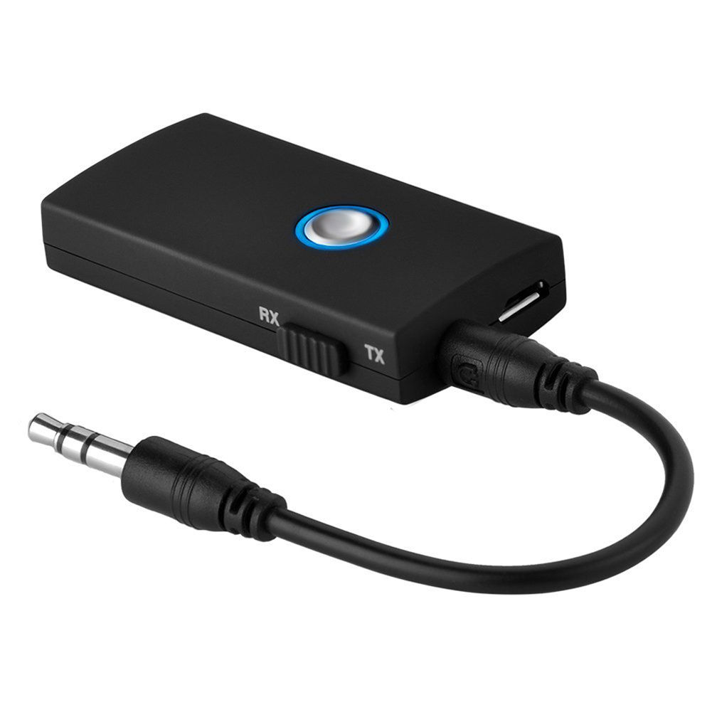
This small gadget turned out to be a very important part of the entire project. The Toshiba tablet has a rather unusual interference quirk that initially caused me hours of frustration. It turns out that significant amounts of radio noise are injected into the SDR when the tablet’s external speakers are active. One way to fix this is to plug a pair of headphones into the tablet’s line out jack, but this forces the listener to be glued to the device. The alternative is to pair the tablet with a Bluetooth audio receiving unit, such as the one listed above. It is worth noting that my other Windows tablet — a Dell Venue 8 — also suffers from this strange artefact.
Total cost: $610
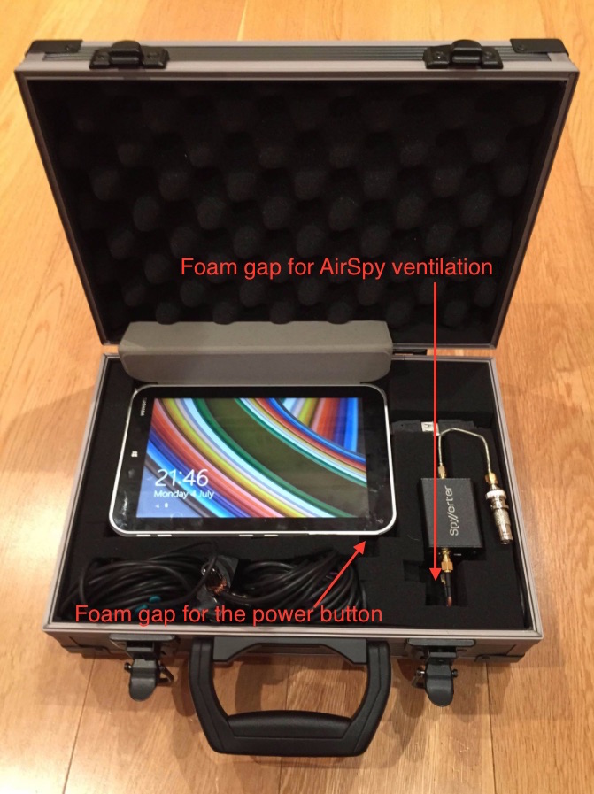
Internal layout of the flight case
You’ll see that I have stacked the SpyVerter enclosure on top of the AirSpy one. As the latter can get very hot, it is essential to leave a sufficiently large gap in the foam for ventilation. It’s also worth leaving a small gap next to the tablet’s power button to prevent Windows from accidentally going into standby mode.
Software configuration
The best software to use with the AirSpy/SpyVerter combination is SDR#. It offers an impressive collection of features that many software packages and conventional radios don’t have, such as advanced noise reduction and synchronous detection with passband tuning. The following adjustments are required to make recording the spectrum a seamless experience:
Install the Baseband Recorder and File Player plugins
Baseband Recorder: this plugin enables efficient recording of very large spectrum (or “baseband”) files. Download and decompress the plugin zip file. Copy the .dll files into the directory with the SDRSharp.exe executable. Open the MagicLine.txt file and copy the first line of text into Plugins.xml file, just before the “</sharpPlugins>” line.
File Player: this plugin enables the playback of recordings made with the Baseband Recorder plugin. Download and decompress the plugin zip file. Copy the .dll files into the directory with the SDRSharp.exe executable. Open the MagicLine.txt file and copy the first line of text into FrontEnds.xml file, just before the “</frontendPlugins>” line.
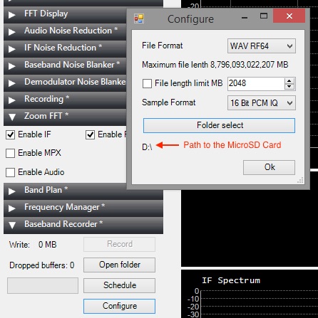
Configure Baseband Recorder
Open SDRSharp.exe and check that the program reports no errors when it loads.
Baseband Recorder configuration
In the plugin pane on the left, expand the Baseband Recorder tab and click “Configure”. Change the File Format to WAV RF64 and make sure that the File length limit check box is not ticked. Click “Folder select” and choose the MicroSD card as the destination directory for the recordings.
Adjust AirSpy settings
Disclaimer: in this section I describe how I capture the maximum spectrum bandwidth that my tablet’s CPU can handle. It involves operating SDR# in “debug mode” and exposes some internal functionality of AirSpy, which, if used incorrectly, can damage the radio. If you choose to copy my approach, please understand that you are doing so at your own risk and follow my instructions carefully to avoid voiding your AirSpy warranty.
Open SDRSharp.exe.Config file in Notepad. Look for “<add key=”airspy.debug” value=”0″ />” line and change it to value=”1″.
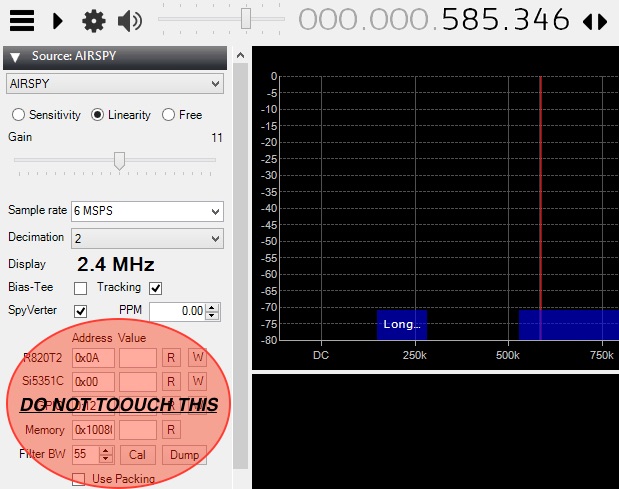
Once the AirSpy and SpyVerter have been connected to the tablet, open SDR# and select AIRSPY in the Source tab. You will see the following configuration dialog.
AirSpy configuration
In the “Sample rate” field, type in “6 MSPS”. For the “Decimation” option, choose “2”. This setting will result in spectrum captures of 3 MHz bandwidth (although only 2.4 MHz of it will be shown on the waterfall display). To capture smaller chunks of the spectrum, increase the decimation value. Make sure the SpyVerter check box is ticked. Do not touch any of the fields or buttons under the “Address Value” line.
Make a short test recording
Press the play button in the top left corner and set the desired frequency.
In the Source tab, select the “Linearity” option. Keep increasing the Gain value by one position at a time until you notice that the radio signals suddenly become “saturated” (the waterfall display becomes full of artefacts and the signal you are listening to gets swamped with noise). Take the Gain value back down by two positions. This will ensure high sensitivity while preventing AirSpy from overloading.
In the Baseband Recorder tab, press “Record”. While recording, do not change the radio frequency and do not move/drag the waterfall portion of the display. Stop the recording after a few minutes.
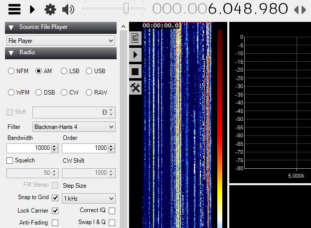
SDR# FilePlayer plugin
In the Source tab, change the input to “File Player” in the drop down menu. Click the Settings cogwheel button and select the spectrum recording file from the MicroSD card. A vertical band visualising the timeline of the spectrum capture will appear immediately to the right of the plugin pane. Click on the play button and select a radio signal to demodulate in the spectrum display. Listen to the audio carefully to make sure there are no dropouts or clicks: if so, your tablet and MicroSD card are capable of handing and storing the specified spectrum bandwidth.
Keep an eye on the gain
While making longer spectrum recordings, select a weak radio signal and keep monitoring its audio for signs of overloading. If the overloading does occur, reduce the Gain value further by one or two positions.
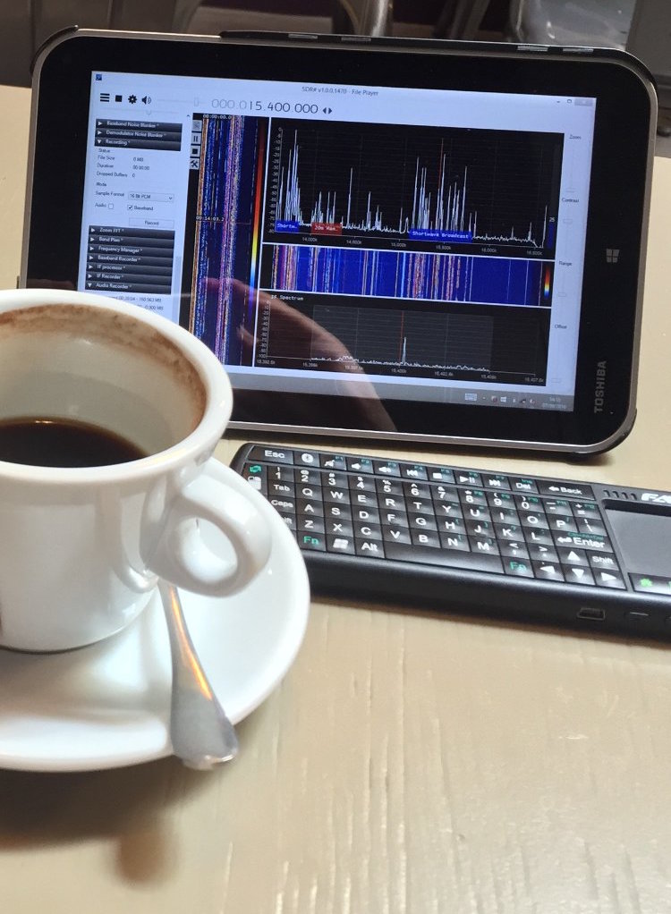
Some example spectrum captures
Shortwave for lunch. Playing back parts of the shortwave spectrum captured earlier in the park, inside a local cafe.
Below are some example videos in which I play back and explore the spectrum recordings I made during the trips to my local park.
In a previous guest post, SWLing Post contributor TomL, shared his “Evolving, Morphing, SW Listening Station” where he detailed the many ways he’s trying to fight heavy radio interference at his listening post. The following post is TomL’s update:
More Anti-Noise Ideas
(Continuing the hunt for better reception in a foul RFI environment)
by TomL
I have made the following changes:
Created a prototype mini-loop based on a crossed-parallel idea from VE1ZAC (Jeff).
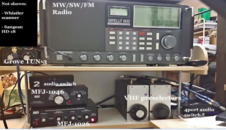
Added 2 preselectors, an old Grove TUN-3 connected to the main loop feed and an MFJ-1046 connected to the ground connection of the balun. Both feeds go into the MFJ-1026.
Added a medium wave noise canceling unit that I have not figured out how to use yet. (Quantum Phaser). The MFJ unit does not work on medium wave without modification.
Purchased from eBay a used Grundig Satellit 800, a somewhat more robust fixed-station receiver to replace my aging Sony ICF-2010.
Other non-related (not shown): Whistler digital scanner + UHF over-the-air TV + FM broadcasts + an AM/FM HD digital radio + high pass filters from MiniCircuits.com – (audio from all these sources is passed to an existing high fidelity stereo power amp and NHT Super One speakers on the computer desk for near-field monitoring). Associated antennas are also hidden on the outside deck (shhhhh!).
Large charge card balance!!
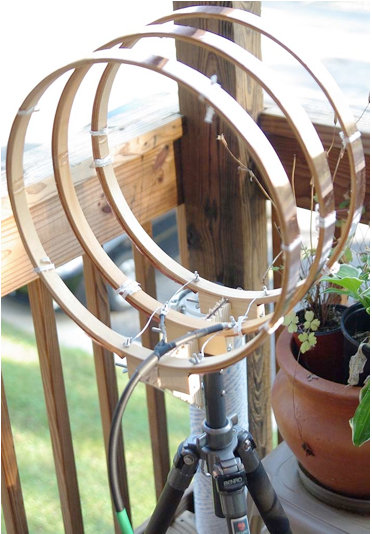
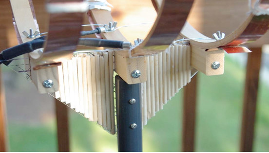
So, here are some pics for the crossed-parallel loop. VE1ZAC web site has all the references if you want to explore further or google him. Mine is purely a prototype and not finished. And should eventually be placed on a rotor (but how to keep my Nazi-like condo association from finding out?!?!?!?).
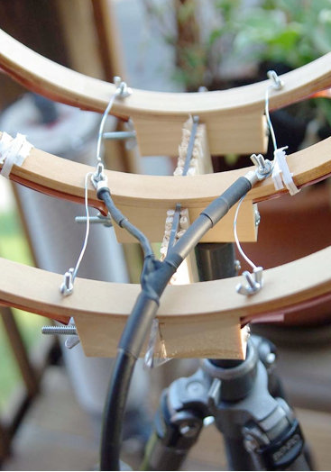
It is three 14 inch quilters hoops from Joann Stores plus some 1-inch copper strips cut from a small 2 meter roll of thin copper from eBay. Then, it is wired in parallel with silver-plated aviation wire on each side with a feed in the middle. Not an optimal placement of the feed, (should go straight down along the pipe). Will fix things up whenever I get some more time.
Seems to be an efficient way to prototype small loops. It is now mounted on a short ¾” inside diameter PVC pipe into a cheap plastic sand-filled deck-umbrella stand. Loops are light and somewhat flimsy, so I mounted the three loops on a plastic triangle ruler and dowel sticks glued to the sides for some extra strength. Good enough for now.
The EF-SWL balun is also in an experimental configuration. Since I read somewhere that loop antennas have a very low impedance at the feed point (like, 10 ohms or lower), I thought I might try a balun that is meant to lower the impedance and mount it backwards. I don’t have a picture of it but the SO-239 output is facing the loop and the screw terminals are facing the direction of the radio. My feeble brain thinks since it is a passive device of coils on ferrite, it should work bidirectionally for receive only applications like this. It seems to work but I have the excuse that I really don’t know what I am doing! 🙂
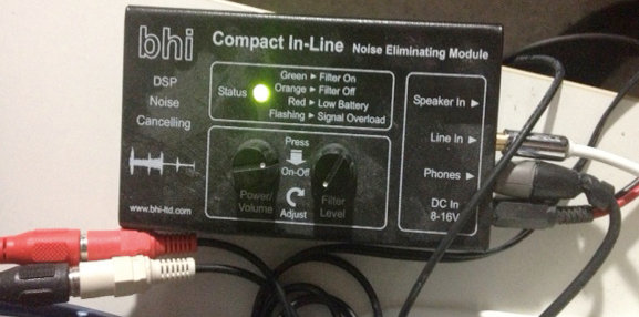
BHI unit in action.
The BHI DSP filter is useful in some circumstances but I find it fatiguing to listen to. The audio from the Sattelit 800 is so nice, I mostly like it without the DSP. The DSP narrows the bandwidth significantly, somewhere around 4 kHz or less from my hearing. I like that the Grundig has two tone controls. And it also has a stable SSB and on very strong signals with clear audio, I like to listen with SSB lower or upper sideband. But the DSP is useful at times for hash-like noisy signals; it is not quite as good on buzzing noise and I wish the Satellit 800 had a noise blanker, but that would have been a more costly purchase, like a Drake R8A.
So, in a nutshell, I have a discovery about noise here: it is all around me and ubiquitous, like the air I breathe!
I find it hard to null and also worry about peaking a station signal at the same time. However, I do have a lower noise floor with the experimental loop sitting outdoors, especially on medium wave (the Wellbrook amp + loop works great on the lower frequencies – am able to get eight different medium wave stations carrying Major League Baseball games at night – it would be nine to get WFAN for the New York Mets but the local Chicago Cubs station covers the adjacent frequency with horrible digital hash! ***Bleeping*** digital junk!).
Also, the signal level is noticeably lower using the loop. Then, add in the effect of the MFJ Noise Canceling unit, the usable signal gets even weaker.
The bottom line is, I can now finally enjoy listening to many SW broadcasts, BUT only the strongest signals. Anything else is still hopelessly lost in the noise. So, gains are limited.
On the other hand, and something else I learned by doing is that, any 1 or 2 dB signal/noise ratio improvement will help with the final audio output in the end product. Using low-noise amps, loops, noise canceler, preselectors, grounded connections, ground isolators at the input of every receiver, high quality stereo amplifier and speakers, tone controls, SSB vs. AM Sync, weird antenna configurations, etc, etc. It all helps in the end to some degree.
Tinkering is an art that involves a lot of thinking/doing iterations! And high quality parts must be used all along the chain or it could degrade the signal.
Below are some audio samples, not very well recorded, but can give some idea of the incremental improvement with each enhancement (turn up the volume). NOTE: other people may get better or worse results depending upon individual situations, type of antennas used, etc, etc.
Recording 1: R. Marti. First 10 seconds an indoor antenna with no noise reduction, second 10 seconds the outdoor loop without the MFJ-1026, the third 10 seconds with the MFJ-1026, then switched off and on to hear the difference.
Recording 2: R. Marti. MFJ -1026 is ON. Last 15 seconds is SSB, very thin sounding. Really only good for strongest signals. I liked the AM Sync better (Satellit 800 is really a Drake SW8 in disguise with a quality AM Sync). But, SSB can sound excellent with very clear voices with a steady and strong signal (The Satellit 800 does NOT have IF-shift or a BFO to fine tune an SSB reception, so the station must be exactly transmitting on the kHz mark, which most are nowadays).
Recording 3: R. Marti. MFJ-1026 is ON. Last 20 seconds you hear me switch in the two audio switches and the BHI DSP is on its lowest setting. Narrower and clearer with some reduction of background noise. I find I only like going up to about 4 on the DSP dial, after that the audio fidelity starts getting more choppy with digital artifacts that sound like dripping water. I tend to like higher fidelity. One nice thing about the BHI DSP is a faux-stereo that helps a little with voice intelligibility by helping the brain naturally filter the noise. Faux-stereo is ON even when the noise reduction circuit is manually turned off (power must be on and bandwidth still sounds narrowed).
Recording 4: R. Nacional Brazilia. First without MFJ-1026, then ON, then OFF, then ON, then with the BHI kicked for the last 20 seconds.
Recording 5: Greece. Switching the MFJ-1026 on and off every 5 seconds. In this particular case, the signal was weak and fading a lot. The MFJ OFF was also weaker than with it turned ON. That is interesting behavior, usually it is opposite. It pays to play with the settings a little. At other times, and less frequently, the MFJ unit turned OFF sometimes sounds better than with it ON and tuned for less noise. Go figure!
After all the tweaking is done, and I cannot get any more performance out of this, I will probably have to move to a nice, quiet neighborhood and setup a nice antenna farm!!
In the meantime, I do enjoy listening to the stronger stations from North America, Cuba, Brazil, Europe, and Australia with less noise than before.
73’s
TomL from NOIZEY Illinoiz
Once again, Tom, thanks for sharing your RFI elimination journey!
I love how you take on this noisy problem by experimenting and seeing it more as a challenge than an obstacle to enjoying your hobby. Great job!
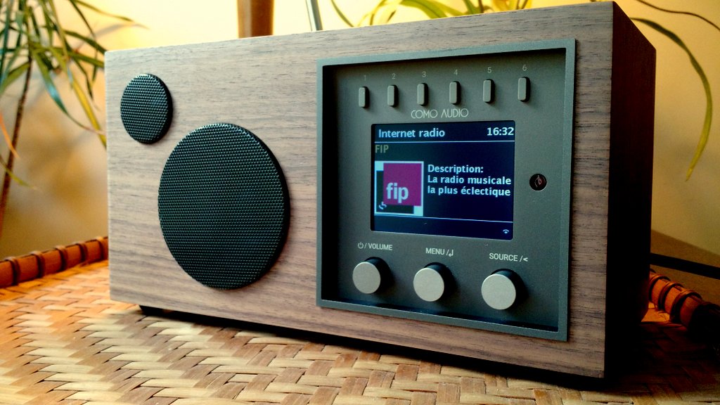
One of the main reasons I purchased the Solo was to use and review it as a WiFi radio. In the Kickstarter campaign, Como Audio didn’t give details about the radio station aggregator the Solo or Duetto would use (click here to read a primer about aggregators). I contacted Como Audio asking for more information and received a reply from Tom DeVesto himself:
Hi Thomas.
Very sorry for the delayed reply.
[…]Our products use Vtuner for the Internet radio stations and Podcasts.
I was a little bummed to have received this information because I’ve heard very little praise for vTuner among WiFi radio enthusiasts.
To make a long story short, I spent a lot of time trying to figure out a way to pair my Solo with the vTuner aggregator. The owner’s manual has no information about using the aggregator nor how to manage and organize stored stations. The only help Como has published thus far is a short video which shows how to add favorites via the radio itself–not via a web portal.
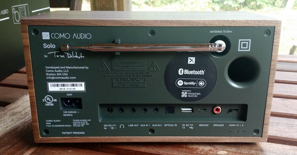
When taking a closer look at the back panel of the Solo, though, I noticed a Frontier Silicon logo.
Wait…what?
My Sangean WFR-28 uses the Frontier Silicon aggregator! This explains why the Solo’s WiFI radio interface looks exactly like that of my WFR-28!
Obviously, somewhere along the way, Como Audio changed aggregators. I’m not at all disappointed as I give Frontier Silicon positive marks in the WFR-28 review.
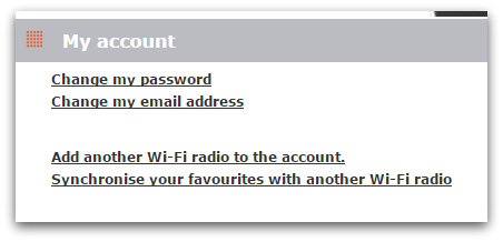
Via Frontier Silicon, you can pair your Como Audio radio to the aggregator database, thus allowing much easier control of memories and station categories through their Radio Portal page! Since this isn’t documented (yet) by Como Audio, here’s how you can easily pair the two:
How to pair your Como Audio device with Frontier Silicon
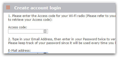
Next, you’ll need to enter the Access code for your Como Audio device. Here are the steps you take to find your unique access code (see images above–same process):
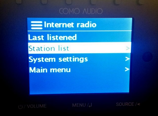
From the Main Menu on your radio, select ‘Internet radio’,
Select “Station list”
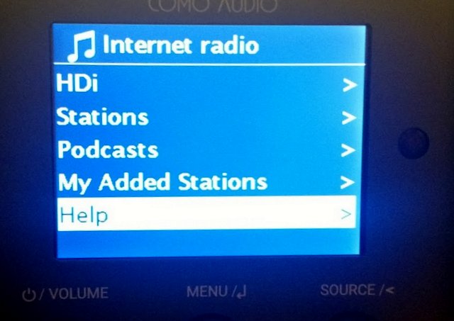
Select the “Help” directory
Select the “Get access code” item
The access code is 7 digits long, simply add it in the Access Code field on the Frontier Silicon web page.
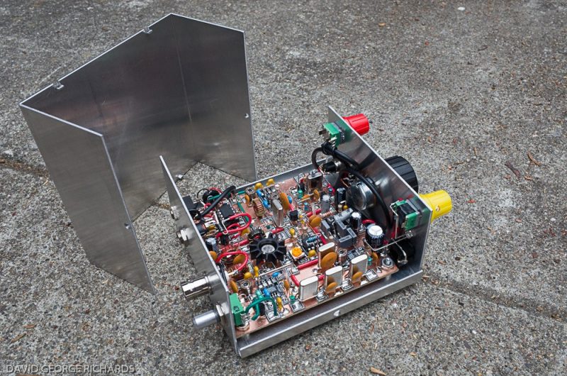
Regular SWLing Post readers might recall the gorgeous Sproutie MKII regenerative receiver my buddy Dave Richards (AA7EE) built last year. No doubt, Dave does a proper job with his homebrew radios–a talented builder and engineer indeed!
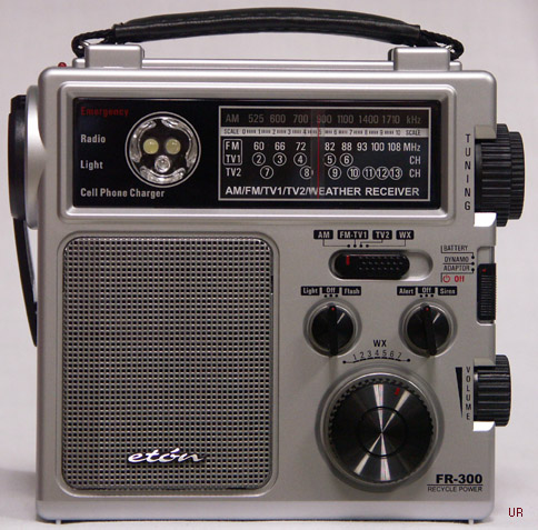
Here in the Houston area we are getting in to the heart of hurricane season. I have a little Eton FR-300 radio that has am, fm, tv and weather bands, a flashing red light, a white light, and a siren. I hadn’t picked it up in some time, and, while doing a “emergency inventory” today, I picked it up and it was so STICKY!!!
The first thing tried was rubbing alcohol, but the type suitable for first aid which is only 50% which just spread the stickiness around.
I did a “sticky radio” search and up came your blog, which I am already familiar with (no stickiness issues on my trusty Sony ICF-SW/7600GR) .
When I browsed the suggested solutions, “citrus-based” came up. Turns out I had the solution under my sink: “Veggie Wash” is a citrus-based product used to clean fruits and vegetables, and now, radios!
Squirted some on a paper towel and it does the job nicely.
Thanks for the suggestion! Like you, I imagine many others will have Veggie Wash on hand.