Many thanks to SWLing Post contributor, Matt Blaze, for the following guest post:
 Matt’s 2022 Portable Loop Antenna Shootout
by Matt Blaze, WB2SRI
Followers of this blog may be familiar with my “shortwave radio shootouts” that I post from time to time. The idea is to compare how well different radios demodulate the exact same signal. Basically, I take a bunch of radios, hook them up to the same antenna via an RF distribution amplifier, tune the radios to some distant signal, and record the audio output from them simultaneously. Sometimes that kind of comparison can be more revealing of actual real-world performance than lab measurements or technical specifications.
The other day, I decided to do the same thing, but for antennas instead of radios. Essentially, I inverted the setup. Instead of hooking up different radios to the same antenna, I hooked up identical radios to different portable antennas and recorded them demodulating the same signals at the same time.
In this first of perhaps a series of these antenna shootouts, I wanted to compare three portable amplified magnetic loop antennas. When I say “portable” here, I mean broadband antennas that can pack reasonable compactly for travel and that can be set up and broken down easily for use “on location”, say on a picnic table or hotel balcony, or perhaps installed temporarily on a roof, without too much fuss.
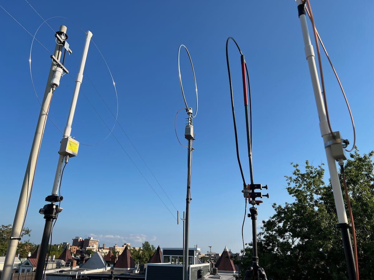
The antennas are:
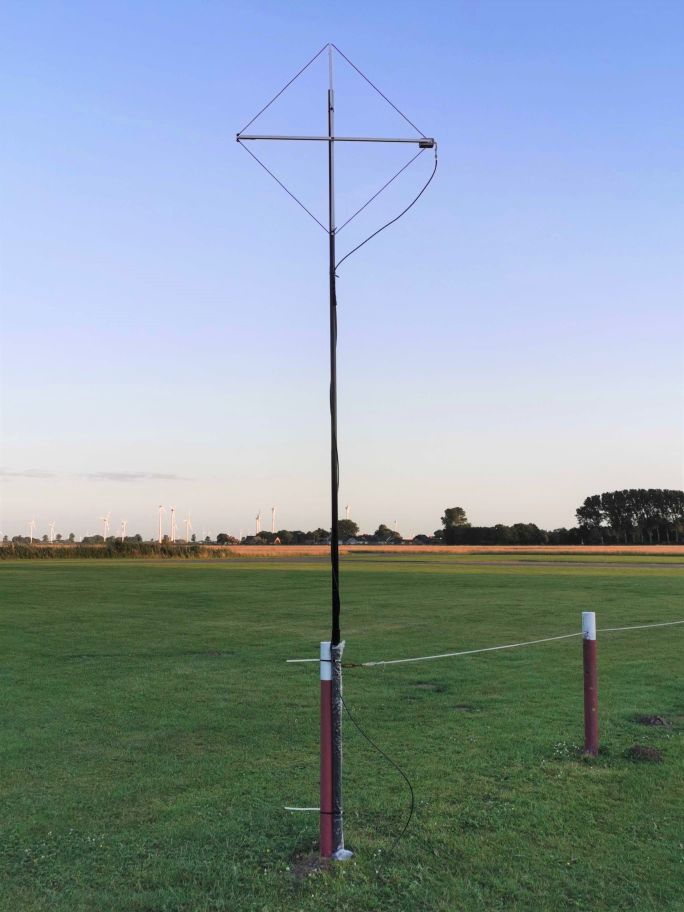
– The Wellbrook FLX1530LN with a 1 meter diameter loop of LMR400 coax. This is my “standard” portable antenna (I use a telescoping broom handle for the support; I wrote about it here as the “signal sweeper” last year). Excellent performance, but on the bulky side for travel. Performs well from LW through HF. Not cheap, at about USD 225 including shipping for the amplifier and power injector, but not including the loop, mounting hardware, or feedline.
– The Wellbrook FLX1530LN with a 0.5 meter diameter loop of RG142 (a stiff “aircraft grade” version of RG58 that holds it shape well at this size). I used some 1/2 inch PVC pipe as the vertical support. Because of the smaller diameter loop and thinner coax, it packs down to a much smaller and lighter package than the 1 meter LMR400 version.
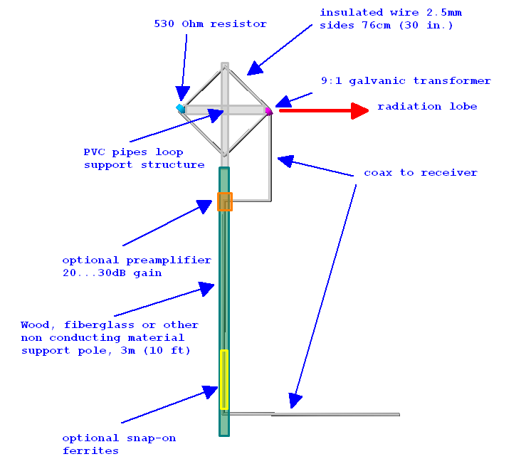
– The K-180WLA, an inexpensive (about USD 60) 0.5 meter loop from China, sold on eBay and Amazon. The loop is steel wire (which can be wound down to a small diameter for transport), and the kit includes everything you need, including a rechargeable power injector. (However, the power injector uses a noisy voltage booster, so I substituted my own bias-T injector for these experiments). Ostensibly covers LW through VHF, but the low end coverage is, shall we say, somewhat aspirational, as you will see.
– I also recorded, for comparison, the built-in ferrite bar (for LW/MW) and whip antenna (for HF) of the receiver.
This is, of course, only a small sampling of portable loop antennas, both commercial and homebrew. But I wanted to start with what I had on hand and with what meets my own needs. (I omitted from consideration loops that require tuning, since I want to be able to install the antenna without needing access to it every time I change frequency).
For each signal captured, I oriented and positioned each antennas to maximize signal quality, taking care to move them away from each other and interfering metal objects. So you’re hearing (approximately) the best each antenna had to offer (on my roof under suboptimal band conditions).
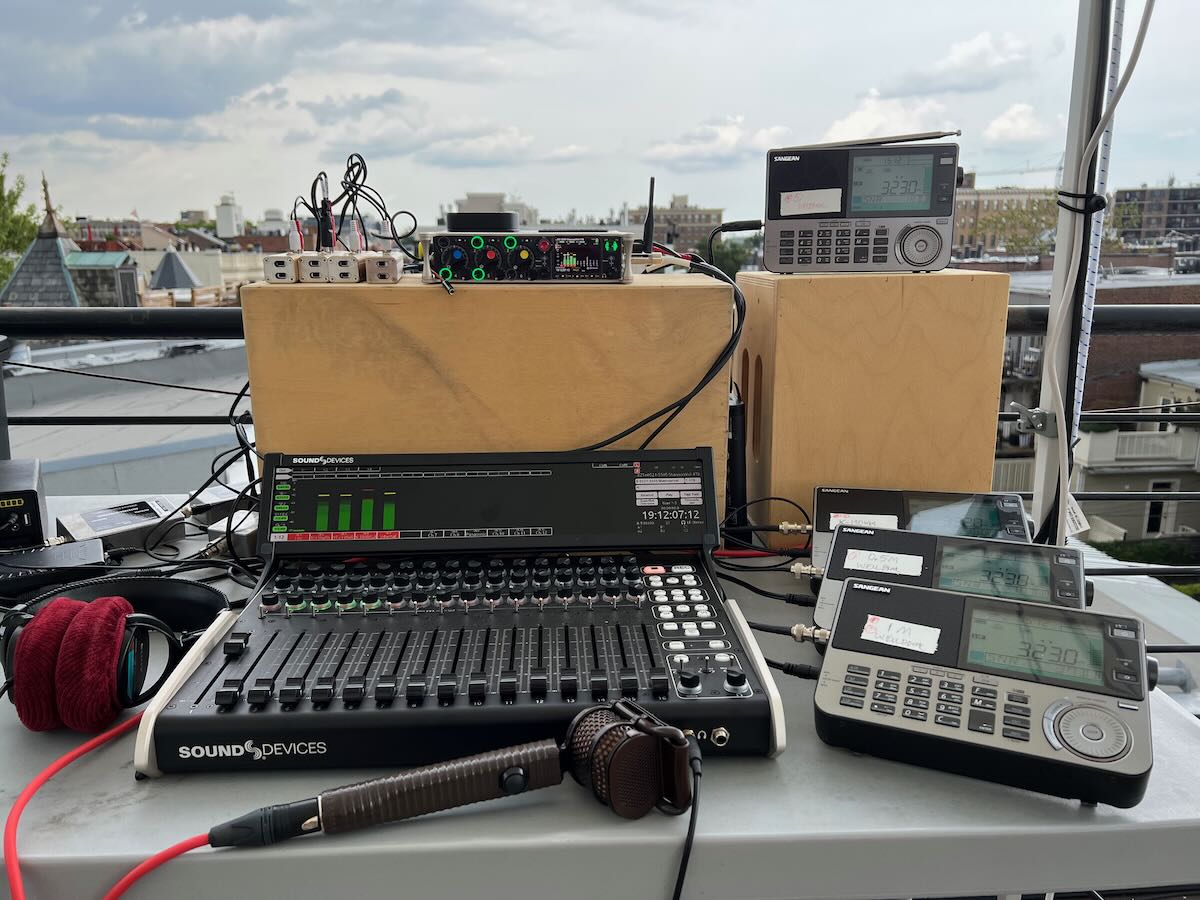
The receivers I used were four Sangean ATS-909×2 portable LW/MW/SW/FM/Air radios. I believe this to be the best currently available (relatively inexpensive) portable shortwave receiver on the market. It has excellent performance (and is admirably resistant to overload and intermod when used with an active antenna). It lacks a sync mode, but that’s rarely implemented well on portable radios anyway. As a practical matter, it has a good line-level output jack, and I already happened to own four of them.
As in my other shootouts, for each signal, there are a total of five recordings: a monoaural recording of the audio from each of the four antennas, plus a narrated stereo recording comparing a reference (the 1M Wellbrook) on the Left channel with each of the other antennas in succession on the Right channel. The stereo recording is intended as a quick overview, but it will only make sense if you listen in stereo, preferably with good headphones. (You can switch the earcups to get a quick comparison as you listen.)