Shortwave listening and everything radio including reviews, broadcasting, ham radio, field operation, DXing, maker kits, travel, emergency gear, events, and more
Many thanks to SWLing Post contributor, Zoltan Azary, who has written an extensive theoretical analysis of ferrite sleeve loop antennas. This article has a very academic flavor and for those who are interested in antenna design, he welcomes your comments!
Many thanks to SWLing Post contributor, Andrew (VK2ZRK), who writes:
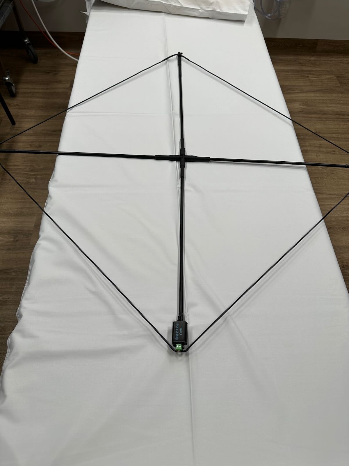
Just thought I would share some pics of my SULA build which I constructed in the Emergency department’s antenna building section in between catastrophies here in Australia.
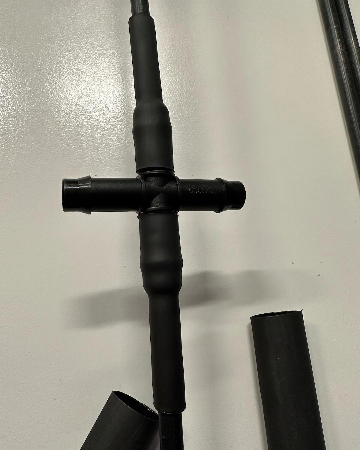
I built it out of 8mm fibreglass tube from a kite supply, 8mm kite nocks, 13mm equal cross irrigation fitting and lots of double wall glue lined heat shrink. The 8mm tube with a short bit of heat shrink is a slip fit into the id of the 13mm equal cross which I secured with more heat shrink.
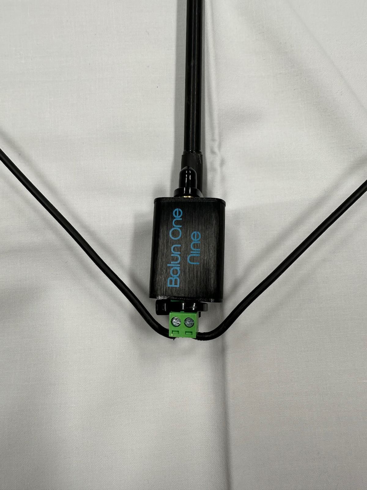
I then cut the frame to length allowing for the length of the kite nocks. I secured the kite nocks with more heat shrink. I then soldered the resister to 2 lengths of Davis RF 12g antenna wire and fed this through the kite nocks terminating it at the nooelec balun on the opposite side to the resistor.
I think it worked out well. It is very light. I built it to use with my SDRPlay RSPdx.
Thank you to everyone involved in the design process and for providing it to the swling.com community.
Cheers
Andrew VK2ZRK
In all the years I’ve been hosting the SWLing Post, I can safely say that we’ve never featured an antenna constructed in an Emergency Department of a hospital. Thank you, Andrew!
The feedback from the SULA antenna build has been phenomenal. The three-part series detailing the SULA antenna from concept to build was the most popular of 2022 on the SWLing Post.
Thank you for sharing the photos of your antenna. What a professional job, Andrew!
Let’s get one thing clear from the start: it’s all Ken Reitz’s fault. When the search for the guilty begins, the finger should point squarely at Mr. Reitz.
Who is Ken Reitz? He is the Managing Editor and Publisher of The Spectrum Monitor.
The Spectrum Monitor is a radio hobbyist magazine available only in PDF format and can be read on any device capable of opening a PDF file. It covers virtually aspect of the radio hobby, and you can find it here: https://www.thespectrummonitor.com/ I am a subscriber, and I can heartily recommend it without reservation.
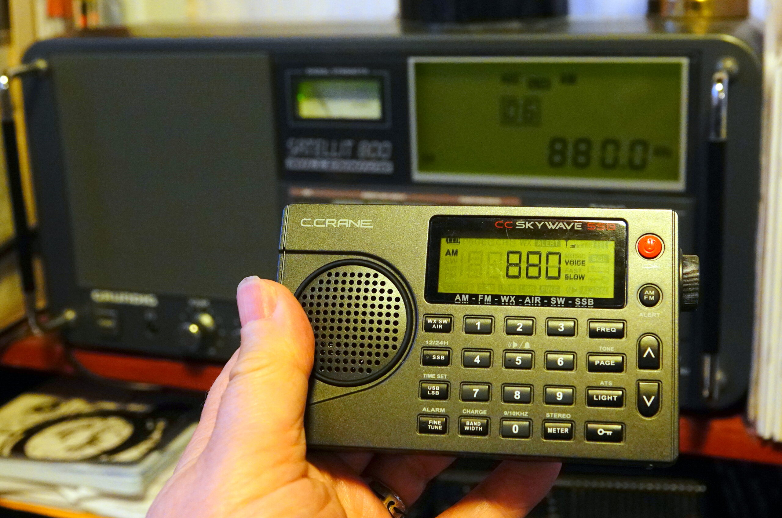
So what is it that Mr. Reitz did that set me off? Short answer: he wrote a really good article entitled “AM DX Antennas: Long Wires and Loops Big and Small.” In it, he mentioned that he could hear, from his location in Virginia, WCBS on 880 in New York City, some 300 miles away. He also mentioned that he could hear, during daylight hours, WGY in Schenectady, NY, about 400 miles distant.
WGY is a local station for me in Troy, NY, but I wondered: Could I hear WCBS in New York City? That’s nearly 150 miles from me. Hmmm.
So I started firing up various radios and radio/antenna combinations on 880 kHz. I tried my Icom IC706 MkIIIG ham transceiver, hooked to the 45-foot indoor end-fed antenna. Nothing heard.
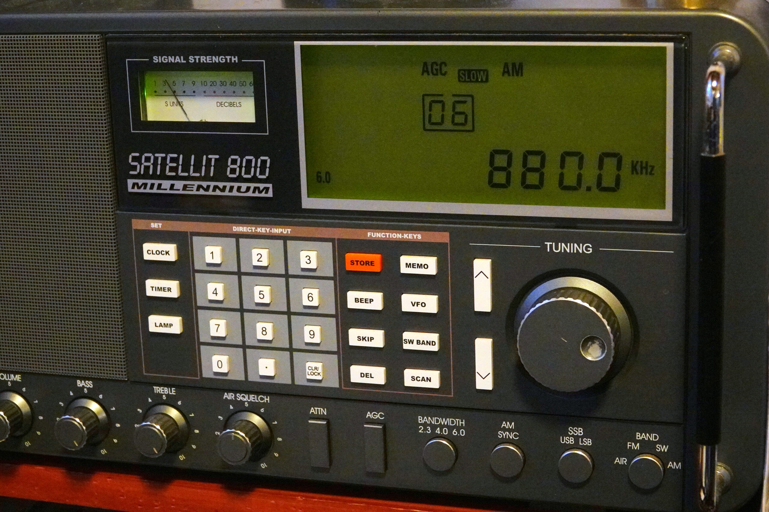
Next, my Grundig Satellit 800 connected to its 4-foot whip antenna. I could hear WCBS barely, but with a horrible buzzing noise. Switching the Satellit 800 to the horizontal room loop antenna I could hear WCBS better, but the noise was really, really nasty.
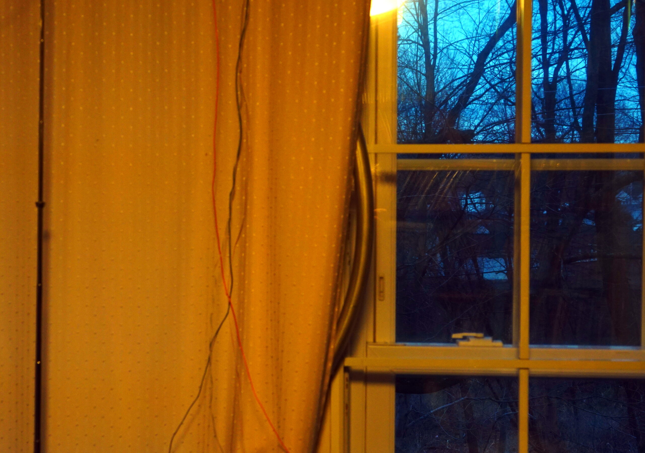
One way to preserve domestic tranquility is to hide the MFJ Loop behind a curtain!
Then I connected the MFJ 1886 Receive Loop Antenna. Tah-dah! I could hear WCBS just fine, with some noise in the background, but “armchair copy.” The MFJ loop made a huge difference in the quality and strength of the signal. I also tried the MFJ loop with another radio I have under test (its identity to be revealed in the future) and found, while I couldn’t hear WCBS at all with the radio’s internal antenna, the 1886 made an enormous difference, pulling out a fully copyable signal with noise in the background.
Finally, I tried a couple of my portables. My Tecsun 880 could hear WCBS, but the noise level was high enough to be annoying. Finally, I tried my CCrane Skywave SSB. The Skywave did a better job of pulling the signal out of the noise. I got the same result with the CCrane Skywave SSB2. Both Skywaves were using their internal ferrite antennas. Impressive.
Bottom line, for this very small foray into daytime medium wave DXing, the MFJ-1886 Receive Loop Antenna was a powerful and useful tool, one I can easily recommend. Second, when it comes to portables, the CCrane Skywave SSB (either model) continues to show that it is “The Little Radio That Could.”
Whether it’s World of Warcraft, Uncharted or the upcoming Super Mario movie – games characters have been all over our cinemas in recent years.
The Last of Us is coming to television screens, where shows based on Resident Evil and Halo have found audiences.
Now, BBC Radio 4 is getting in on the act.
Sam Fisher, leading man from the Splinter Cell game series, can call the radio station home, thanks to a first-of-its-kind adaptation that producers say no-one had thought possible.
Radio 1 film critic Ali Plumb says that with so much competition for audiences these days it’s no surprise that commissioners are giving the green-light to projects with a “built-in audience”.
He argues that we live in a world that is dominated by content: “From podcasts to music, TV, movies, games and audiobooks – frankly its tricky for anyone to cut through the noise.
“The art of finding intellectual property, using the built-in fan base of that property and engaging with them in something you want to say about the world is the trick that many creative people are trying to do.”
Splinter Cell: Firewall is an eight part dramatisation of a novel based on the famous video game franchise. Sam Fisher, the series’ main protagonist, is a covert special agent who excels at sneaking around military bases at night, silently killing terrorist guards and generally saving the world.
Bringing the gaming revolution to audio drama makes perfect sense to actor Andonis Anthony, who plays Sam in the Radio 4 drama, which is also available on BBC Sounds. He argues that with more people turning to “non-music audio”, it’s a good time for BBC radio to tell stories that offer a “cinematic experience”.
“Given the rise in podcasts, and audiobooks being so popular – more and more people are getting used to listening to audio as a story experience. Everyone’s going out and about with their air pods on these days and listening in a different way to before.” [Continue reading…]
Software-defined radio is all the rage these days, and for good reason. It eliminates or drastically reduces the amount of otherwise pricey equipment needed to transmit or even just receive, and can pack many more features than most affordable radio setups otherwise would have. It also makes it possible to go mobile much more easily. [Rostislav Persion] uses a laptop for on-the-go SDR activities, and designed this 3D printed antenna mount to make his radio adventures much easier.
The antenna mount is a small 3D printed enclosure for his NESDR Smart Dongle with a wide base to attach to the back of his laptop lid with Velcro so it can easily be removed or attached. This allows him to run a single USB cable to the dongle and have it oriented properly for maximum antenna effectiveness without something cumbersome like a dedicated antenna stand. [Rostislav] even modeled the entire assembly so that he could run a stress analysis on it, and from that data ended up filling it with epoxy to ensure maximum lifespan with minimal wear on the components. [Continue reading…]
An experiment to bounce a radio signal off an asteroid on Dec. 27 will serve as a test for probing a larger asteroid that in 2029 will pass closer to Earth than the many geostationary satellites that orbit our planet.
The High-frequency Active Auroral Research Program research site in Gakona will transmit radio signals to asteroid 2010 XC15, which could be about 500 feet across. The University of New Mexico Long Wavelength Array near Socorro, New Mexico, and the Owens Valley Radio Observatory Long Wavelength Array near Bishop, California, will receive the signal.
This will be the first use of HAARP to probe an asteroid.
“What’s new and what we are trying to do is probe asteroid interiors with long wavelength radars and radio telescopes from the ground,” said Mark Haynes, lead investigator on the project and a radar systems engineer at NASA’s Jet Propulsion Laboratory in Southern California. “Longer wavelengths can penetrate the interior of an object much better than the radio wavelengths used for communication.”
Knowing more about an asteroid’s interior, especially of an asteroid large enough to cause major damage on Earth, is important for determining how to defend against it.
“If you know the distribution of mass, you can make an impactor more effective, because you’ll know where to hit the asteroid a little better,” Haynes said.
Many programs exist to quickly detect asteroids, determine their orbit and shape and image their surface, either with optical telescopes or the planetary radar of the Deep Space Network, NASA’s network of large and highly senstive radio antennas in California, Spain and Australia.
Those radar-imaging programs use signals of short wavelengths, which bounce off the surface and provide high-quality external images but don’t penetrate an object.
HAARP will transmit a continually chirping signal to asteroid 2010 XC15 at slightly above and below 9.6 megahertz (9.6 million times per second). The chirp will repeat at two-second intervals. Distance will be a challenge, Haynes said, because the asteroid will be twice as far from Earth as the moon is.
The University of Alaska Fairbanks operates HAARP under an agreement with the Air Force, which developed and owned HAARP but transferred the research instruments to UAF in August 2015.
The test on 2010 XC15 is yet another step toward the globally anticipated 2029 encounter with asteroid Apophis. It follows tests in January and October in which the moon was the target of a HAARP signal bounce.
Apophis was discovered in 2004 and will make its closest approach to Earth on April 13, 2029, when it comes within 20,000 miles. Geostationary satellites orbit Earth at about 23,000 miles. The asteroid, which NASA estimated to be about 1,100 feet across, was initially thought to pose a risk to Earth in 2068, but its orbit has since been better projected by researchers.
The test on 2010 XC15 and the 2029 Apophis encounter are of general interest to scientists who study near-Earth objects. But planetary defense is also a key research driver.
“The more time there is before a potential impact, the more options there are to try to deflect it,” Haynes said.
NASA says an automobile-sized asteroid hits Earth’s atmosphere about once a year, creating a fireball and burning up before reaching the surface.
About every 2,000 years a meteoroid the size of a football field hits Earth. Those can cause a lot of damage. And as for wiping out civilization, NASA says an object large enough to do that strikes the planet once every few million years.
NASA first successfully redirected an asteroid on Sept. 26, when its Double Asteroid Redirection Test mission, or DART, collided with Dimorphos. That asteroid is an orbiting moonlet of the larger Didymos asteroid.
The DART collision altered the moonlet’s orbit time by 32 minutes.
The Dec. 27 test could reveal great potential for the use of asteroid sensing by long wavelength radio signals. Approximately 80 known near-Earth asteroids passed between the moon and Earth in 2019, most of them small and discovered near closest approach.
“If we can get the ground-based systems up and running, then that will give us a lot of chances to try to do interior sensing of these objects,” Haynes said.
The National Science Foundation is funding the work through its award to the Geophysical Institute for establishing the Subauroral Geophysical Observatory for Space Physics and Radio Science in Gakona
“HAARP is excited to partner with NASA and JPL to advance our knowledge of near-Earth objects,” said Jessica Matthews, HAARP’s program manager.
I’m Giuseppe Morlè from central Italy, Formia on the Tyrrhenian Sea…
My Cassette Loop experiment this time shows how induction takes place on short waves after medium waves.
I used a smaller box as the primary antenna which, however, is pushed by the secondary one due to the induction effect generated between the two windings brought closer together.
This way, the larger loop “captures” more of the signal and sends it to the smaller cassette…
I really like working on induction… I hope you like it:
I’m Giuseppe Morlè from Formia on the Tyrrhenian Sea…
I wanted to share this experiment of mine with all of you by tuning the medium waves with two separate loop cassettes and each for itself by exploiting the principle of induction between two conductors placed next to each other.
I superimposed one cassette on the other by matching the windings of the medium waves–each variable works only for its own box.
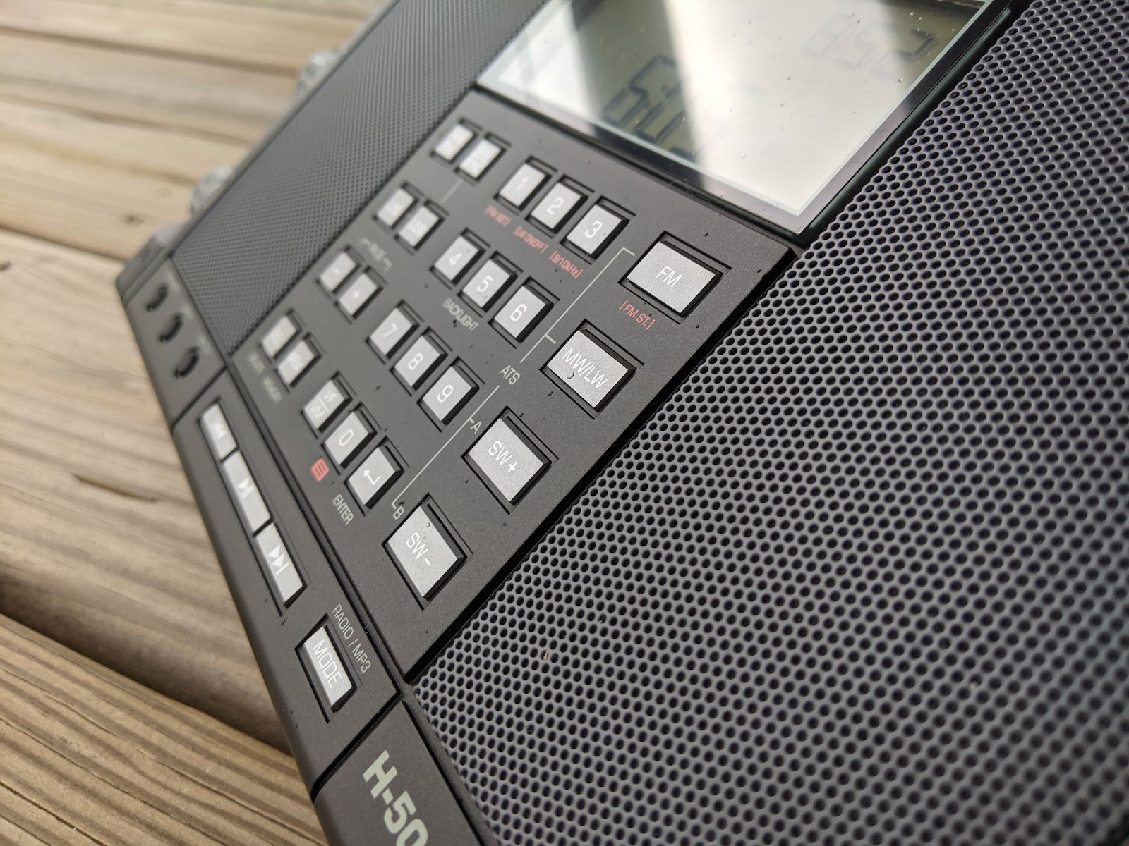
I’m tuning the Algerian JIL FM station on 531 kHz with the Tecsun H-501X connected to the box below…then, passing to the top box, the one without any physical contact with the receiver, I tuned this station again centering it perfectly thanks to the induction that creates between the two close windings.
My video will clarify any doubts and I would like to receive your comments about it.
My constructions are the result of continuous recycling and spending very little to get a good yield.
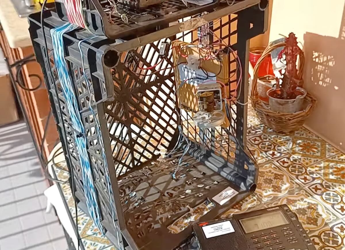
This is Giuseppe Morlè. As always, I try recycling what I have and improving upon antennas I’ve built in the past. This is one way we radio lovers can experiment. Many years ago, I made an antenna only for medium waves; by adding a circuit, I can now listen to short waves.
I took advantage of a small frame that I recovered from an old commercial FM / AM stereo receiver by removing its coils for medium waves and I wound around it only two coils sufficient to have a frequency range from 3.5 to 18 MHz.
I remember that the antenna in question also receives medium waves as it was born.
I chose this small frame because I wanted everything to be small in order to carry this compact antenna everywhere.
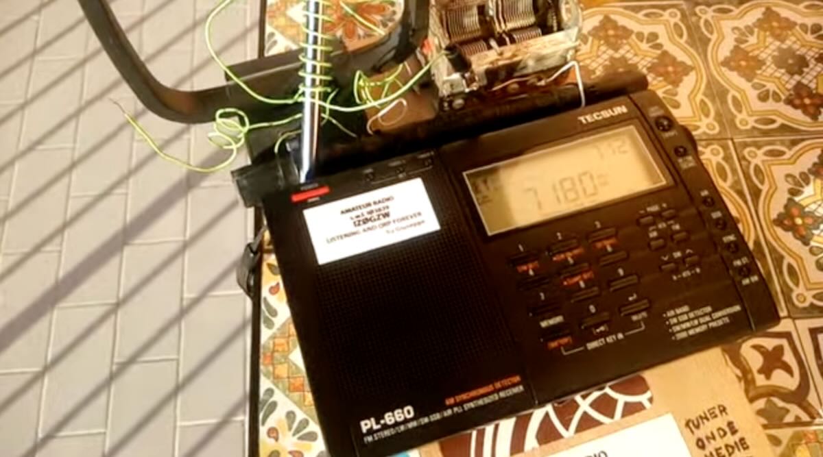
Unlike my other projects for SW and MW, which have a cable that carries the SW signal to the receiver, this time I used the induction that is created around one end of the loop, which I spiraled to get inside the stylus of my Tecsun PL-660 and which then transfers the signal to the receiver.
I did some tests on my balcony the day after a strong storm and I noticed that the propagation was absent but I still wanted to make sure that everything was working.
I will keep you updated on other tests on more favorable days of propagation … I still invite you to follow me on my Youtube channel.
I wish everyone a good listening …
73. Giuseppe Morlè iz0gzw.
Many thanks, Giuseppe. I, for one, love all of your homebrewed and recycled antennas. This one is no exception! What a fun project. I love how you use what you have and aren’t afraid to experiment! Thank you for sharing.

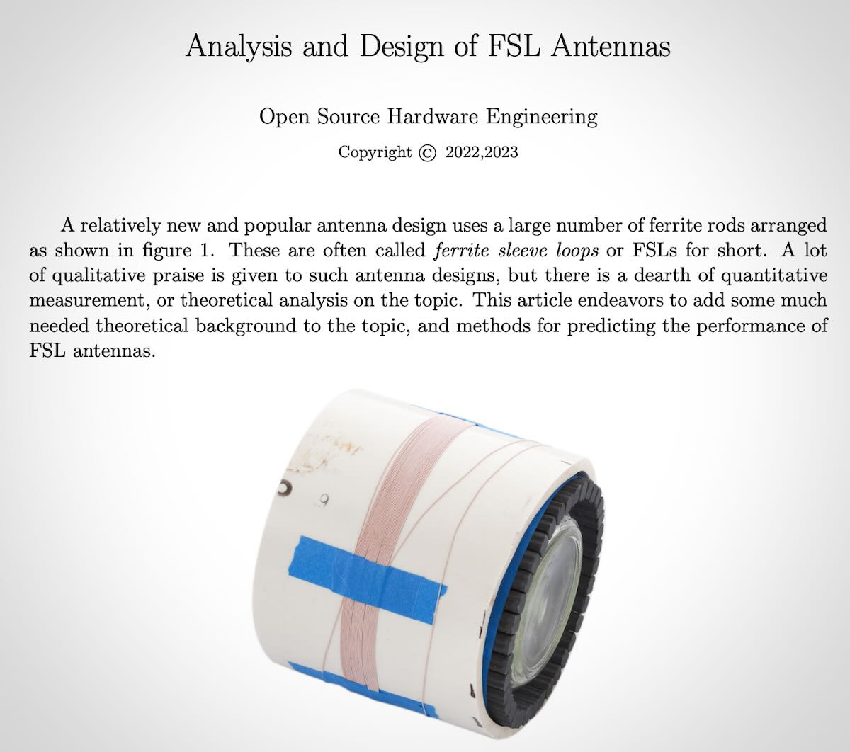 Many thanks to SWLing Post contributor, Zoltan Azary, who has written an extensive theoretical analysis of ferrite sleeve loop antennas. This article has a very academic flavor and for those who are interested in antenna design, he welcomes your comments!