Tag Archives: Antennas

Introducing the amazing SULA: An affordable unidirectional DX-grade loop antenna that you can build!

Many thanks to SWLing Post contributor extraordinaire, 13dka, who brings us a three part series about the new SULA homebrew antenna project. This first article describes this affordable antenna and demonstrates its unique reception properties. The second article will focus on construction notes. The third and final article will essentially be a Q&A about the SULA antenna. All articles will eventually link to each other once published.

This wideband unidirectional antenna is an outstanding and innovative development for the portable DXer. I love the fact that it came to fruition via a collaboration between Grayhat and 13dka: two amazing gents and radio ambassadors on our SWLing.net discussion board and here on the SWLing Post. So many thanks to both of them!

Please enjoy and share SULA Part 1:


Introducing the Small Unidirectional Loop Antenna (SULA) 1-30MHz

A small and simple, unidirectional and DX-capable loop “beam” for SWLs!

by 13dka

In early June, Andrew (grayhat), SWLing Post‘s resident antenna wizard suggested a variation of the “cardioid loop” on the SWLing Post message board: The original “cardioid loop” is a small loop receiving antenna deriving its name from a cardioid shaped (unidirectional) radiation footprint. The design is strikingly simple but it has a few downsides: It relies on a custom preamp, it needs a ground rod to work and it is unidirectional only up to 8 MHz.

Andrew’s version had the components all shuffled around and it did not only lose the ground rod, it also promised a nice cardioid pattern over the entire shortwave, from a small, diamond shaped loop. Wait…what? It can be made using parts available on Amazon and your DIY store:

You need some 3m wire and PVC tubes to create a support structure to hold the wire, a 530 Ohm resistor and a 9:1 balun like the popular “NooElec One Nine”. Since it’s a “lossy” design, adding a generic LNA like the NooElec “LANA HF” would help getting most out of it. When you put that all together you have what sounds like an old shortwave listener’s dream: a small, portable, tangible, and completely practical allband shortwave reception beam antenna with some more convenient properties on top, for example, it is a bit afraid of heights.

That sounded both interesting and plain crazy, but the .nec files Andrew posted were clearly saying that this antenna is a thing now. Unfortunately Andrew suffered a little injury that kept him from making one of those right away, I on the other hand had almost all the needed parts in a drawer so I ended up making a prototype and putting it through some of its paces, with Andrew changing the design and me changing the actual antenna accordingly, then mounting it upside down. Let me show you around:

  •  Small, diamond shaped wire loop (with 76cm/29.92″ sides), needing as little space as most other small loops.
  • Unidirectional with a ~160° wide “beam” and one pronounced minimum with a front/back-ratio of typically 20dB over the entire reception range 1-30MHz.
  • Moderate height requirements: It works best up to 3m/10′ above ground, where it gives you…
  • …a main lobe with a convenient flat takeoff angle for DX
  • Antenna is comparatively insensitive to ground quality/conductivity.
  • Wideband design, works best on shortwave and is pretty good up to 70cm.

A functional small beam antenna for shortwave reception that’s just as small and possibly even more lightweight (prototype:~250g/9oz) than your regular SML, that can be easily made out of easy to obtain parts and easily carried around for mobile/portable DXing and due to its cardioid shaped directional pattern also for direction finding, a “tactical” antenna that’s also doing DX? Unlike conventional, Yagi-Uda or wire beams it can achieve a low takeoff angle at only 3m/10ft height or less, the front/back ratio is typically better than that of a 3-element Yagi, with a particularly useful horizontal pattern shape. That it’s rather indifferent to soil quality could mean that more people get to reproduce the good results and being a real wideband antenna is making the SULA an interesting companion for multiband radios and SDRs. Really? A miracle antenna? Is it that time of year again? If I had a dollar for every….

Continue reading

Spread the radio love

Frans compares the BH5HDE QRP, GRAHN SE3, and his home made loop antenna

Many thanks to SWLing Post contributor, Frans Goddijn, who shares the following article and video originally posted on his blog:

I got the little BH5HDE QRP portable QRP loop, assembled it and could not wait to try it out even though it was during that day and signals were sparse and weak.

This new loop performs well, in part thanks to the tuning & impedance knobs. I compare it with the GRAHN SE3 and a big home made loop that I bought second hand. The latter has no tuning but is as directionally sensitive as the others and it delivers an amplified signal to the receiver.

Click here to view on YouTube.

I found a manual for the QRP, not included in the package:

Instructions for use of BH5HDE QRP portable small loop antenna

Welcome to use the BH5HDE QRP portable small loop antenna. This product can easily and quickly set up a short-wave transceiver antenna, allowing you to enjoy the joy of multi-band reception and communication indoors, windows, balconies and outdoors.

Installation:
(BNC mount equipment needs to bring a pair of photography tripods)
Use the right-angle adapter and double male docking to connect the antenna to the m seat at the rear of the radio station or erect the ring body to the connector on both sides of the controller and tighten, then install the tripod to the fastening seat on the back of the tuner Open the tripod, place the antenna body firmly on the tripod, and finally connect the feeder (the feeder is attached with a choke, one end of the choke is placed near the small loop antenna).

use:
Now that the small loop antenna has been connected to your radio station, you can now tune in.
First introduce the function of the tuner panel. The toggle switch on the left is the band selection switch (up: 7MHz, down: 14-30MHz).
The main control knob, the upper knob is the frequency tuning knob, the frequency tuning value does not change due to environmental changes; the lower knob is the impedance matching knob, the impedance matching value will change due to environmental changes. (The tuning range of the two knobs is 180 degrees, and the panel value is 0-60).
When you start using the radio, select the desired frequency, and then turn the band switch to the desired band position, then adjust the impedance matching value of the lower knob to 30, and then adjust the upper knob to tune. At this time, pay attention to listening to the noise floor of the radio station. The more resonance, the louder the noise floor of the radio station (in the environment with extremely low noise floor, the antenna resonance noise floor is almost inaudible. It is recommended to let the radio station observe the standing wave). At this time, let the radio transmit (cw, fm, and am modes are available), pay attention to the standing wave indication, and fine-tune the frequency tuning knob while transmitting. Since the knob of the portable version does not have a deceleration function, the method of fine adjustment must be more delicate, and the smaller the rotation angle, the better.

At this time, you can observe a significant change in the standing wave, but generally the minimum standing wave ratio will not be below 1.5. At this time, you need to adjust the impedance matching knob. It is recommended to adjust the positive and negative 5 scale values randomly, and then repeat the frequency tuning steps and observe The standing wave ratio. Due to the change in the matching value, there are two possibilities before the comparison: 1: the minimum value of the standing wave ratio decreases; 2 the minimum value of the standing wave ratio becomes larger. If the minimum value of the standing wave ratio becomes lower, it means that the impedance matching adjustment approaches the correct value and can be further adjusted. If the minimum value of the standing wave ratio becomes larger, it means that the impedance matching is far from the correct value and must be adjusted in the opposite direction.

Repeat the above steps to adjust the VSWR of the antenna to 1.0.

The VHF and UHF bands are fixed with the upper knob hitting 60 to the end, and the lower knob can adjust the impedance to resonate.

Note: The best effect for outdoor use is to use antennas indoors as close as possible to windows, fully enclosed reinforced concrete, against walls and other environments where the standing wave ratio is not ideal.

Advanced technique: when the signal is weak, you can rotate the antenna direction to improve the signal-to-noise ratio, which is conducive to reception. The unique gain lobe of the loop antenna makes the horizontal gain directivity when it is erected, and its characteristics can be used to select multiple signals in the horizontal direction. It can also reduce the co-frequency interference in the horizontal direction. Of course, If the interference signal is extremely strong, much larger than the useful signal that needs to be accepted, the attenuation effect will not be too significant, compared to the whip antenna can still have the attenuation effect.

Spread the radio love

Radio Waves: DRM Part of BBC Story, Antennas and Smith Charts, Shortwave “Hot Debate,” Carrington Event, and “Deep Freeze”

Radio Waves:  Stories Making Waves in the World of Radio

Welcome to the SWLing Post’s Radio Waves, a collection of links to interesting stories making waves in the world of radio. Enjoy!
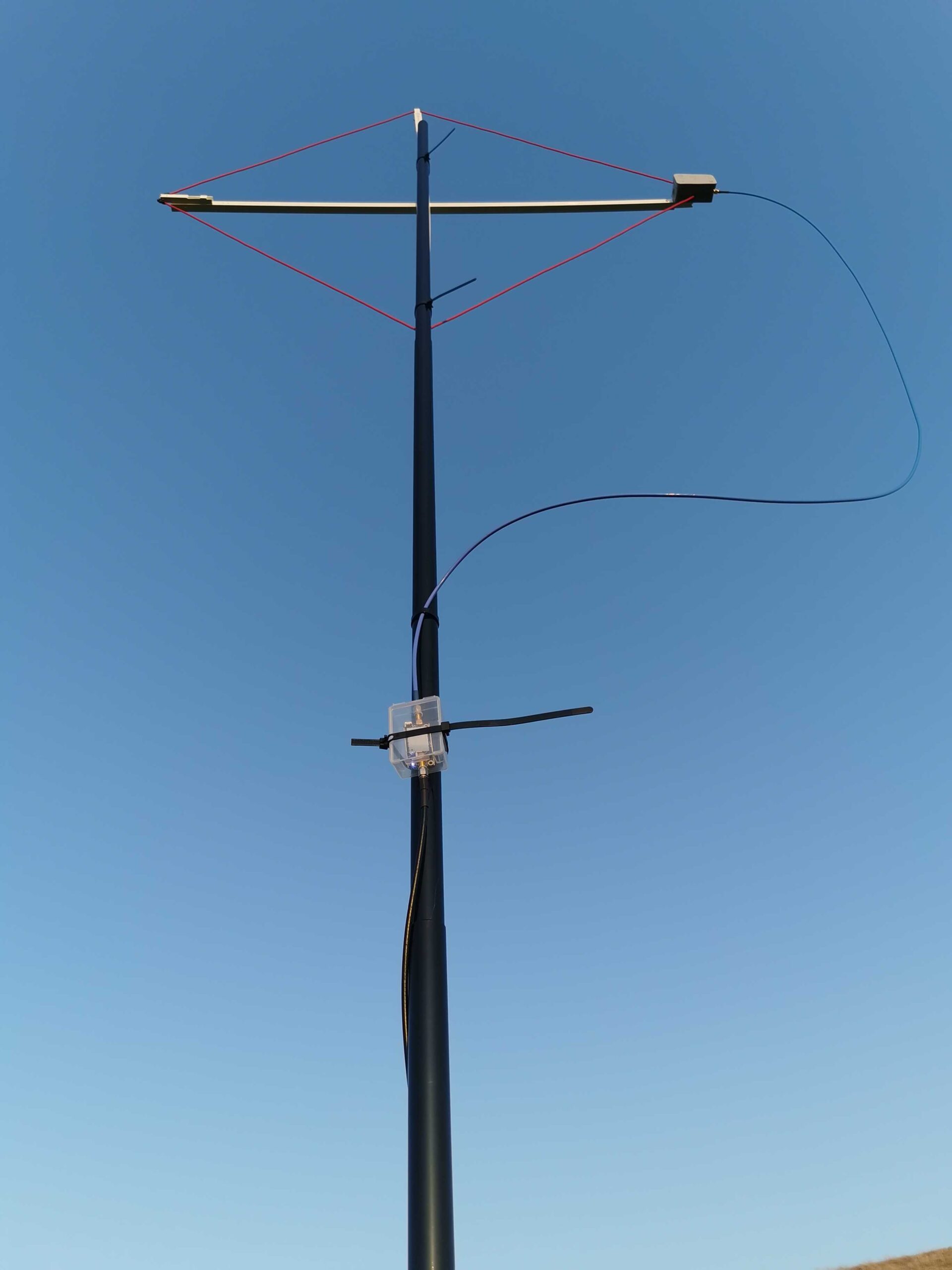
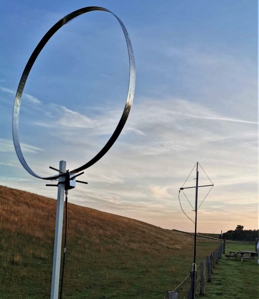
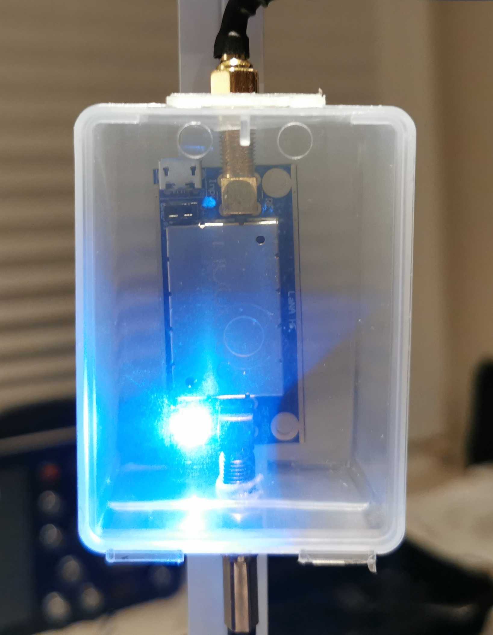
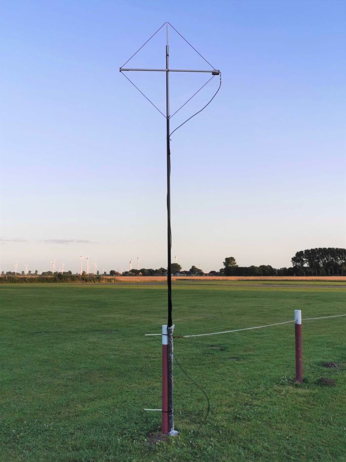
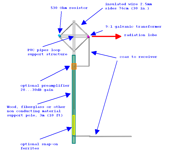
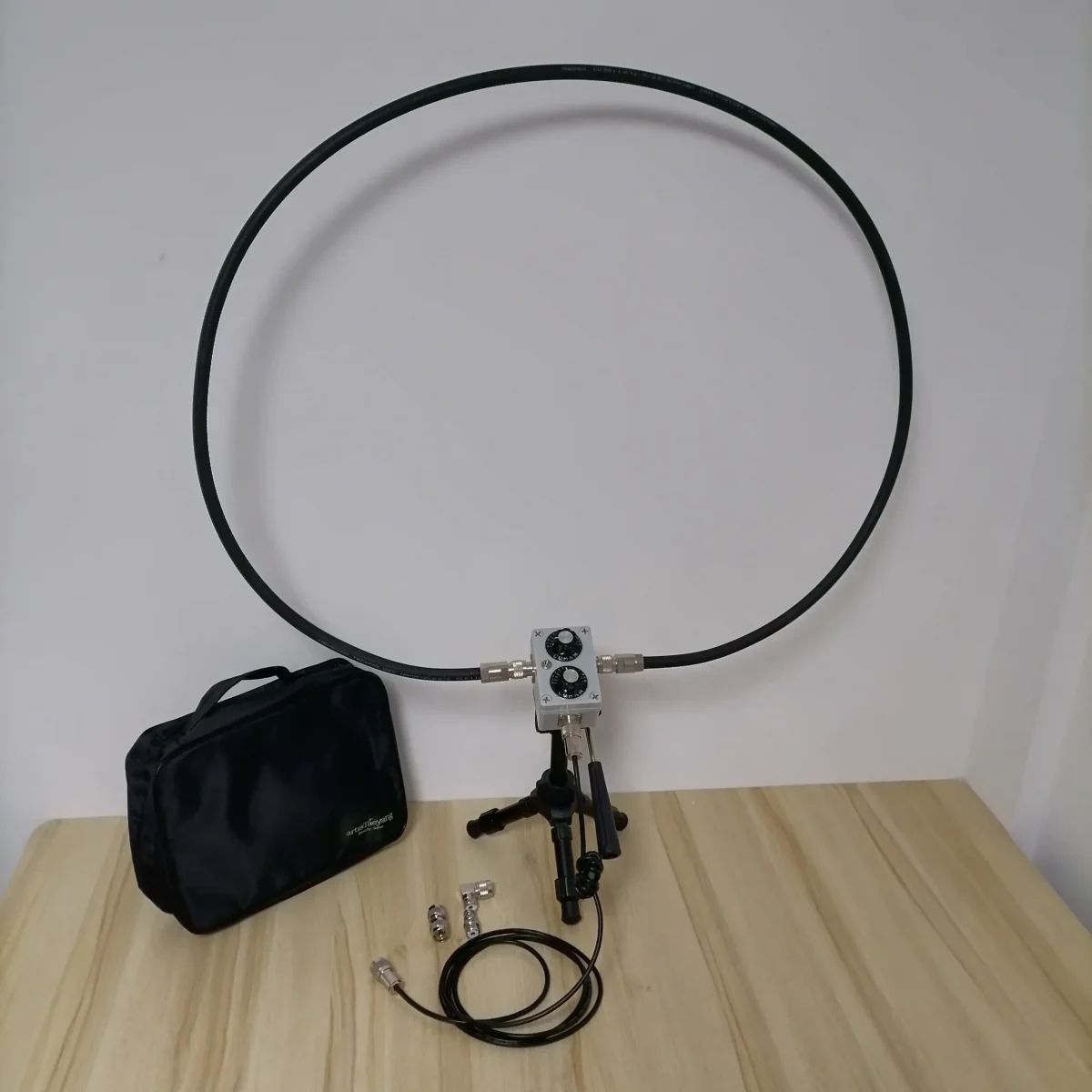
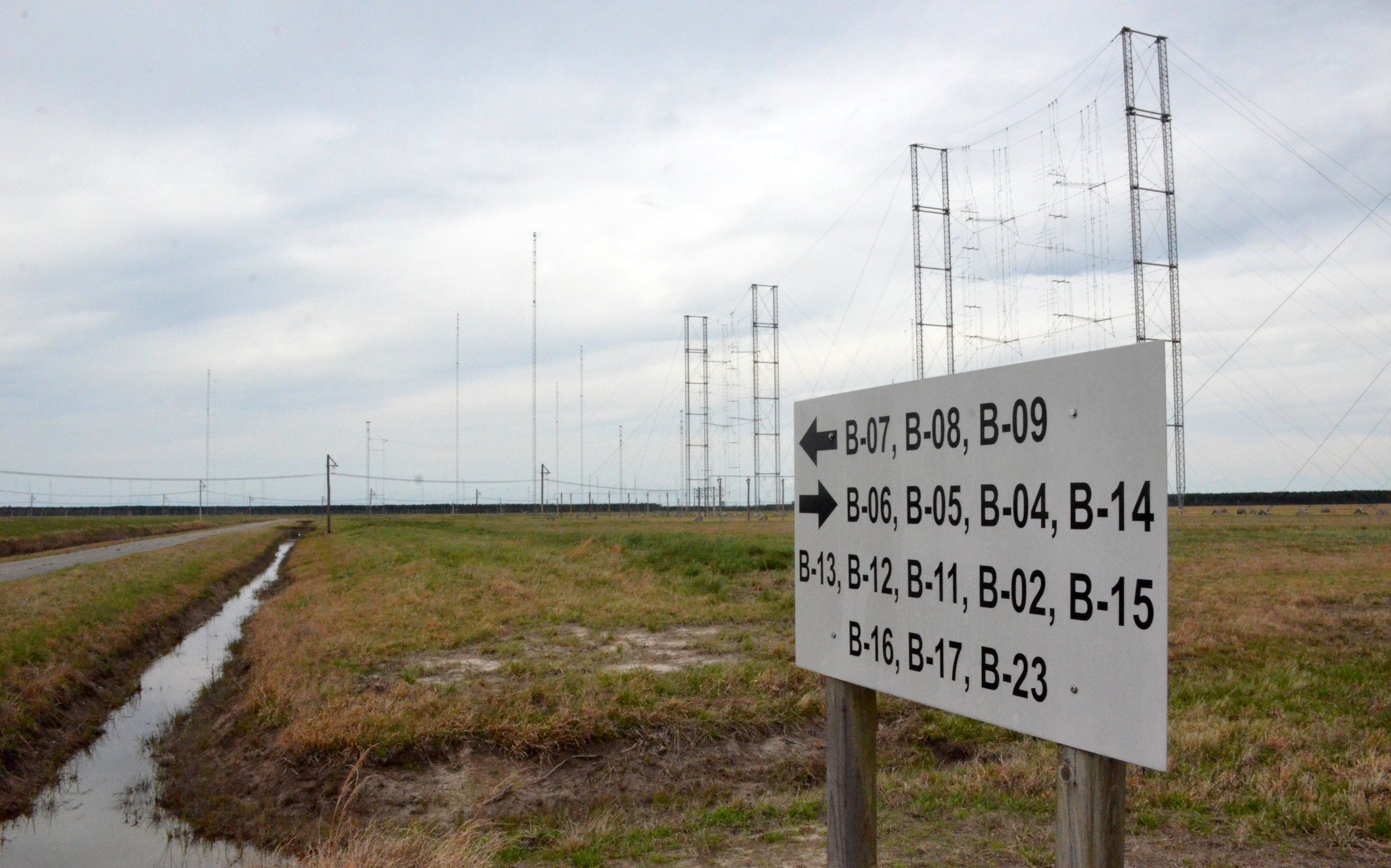

DRM Is Part of the BBC World Service Story (Radio World)

The iconic broadcaster has been supportive of the standard for over 20 years

The author is chairman of the DRM Consortium. Her commentaries appear regularly at radioworld.com.

Our old friend James Careless studiously ignores DRM once more in his well-researched, but to our minds incomplete article “BBC World Service Turns 90” in the March 30 issue.

As an ex-BBC senior manager, I would like to complete the story now that the hectic NAB Show is over.

Having lived through and experienced at close quarters the decision to reduce the BBC shortwave about 20 years ago, I can confirm that the BBC World Service decision to cut back on its shortwave footprint — especially in North America, where reliable, easy-to-receive daily broadcasts ceased — has generated much listener unhappiness over the years.

In hindsight, the decision was probably right, especially in view of the many rebroadcasting deals with public FM and medium-wave stations in the U.S. (and later other parts of the world like Africa and Europe) that would carry news and programs of interest to the wide public.

But BBC World Service in its long history never underestimated the great advantages of shortwave: wide coverage, excellent audio in some important and populous key BBC markets (like Nigeria) and the anonymity of shortwave, an essential attribute in countries with undemocratic regimes.

BBC World Service still enjoys today about 40 million listeners worldwide nowadays. [Continue reading…]

The Magic of Antennas (Nuts & Volts)

If you really want to know what makes any wireless application work, it is the antenna. Most people working with wireless — radio to those of you who prefer that term — tend to take antennas for granted. It is just something you have to add on to a wireless application at the last minute. Well, boy, do I have news for you. Without a good antenna, radio just doesn’t work too well. In this age of store/online-bought shortwave receivers, scanners, and amateur radio transceivers, your main job in getting your money’s worth out of these high-ticket purchases is to invest a little bit more and put up a really good antenna. In this article, I want to summarize some of the most common types and make you aware of what an antenna really is and how it works.

TRANSDUCER TO THE ETHER
In every wireless application, there is a transmitter and a receiver. They communicate via free space or what is often called the ether. At the transmitter, a radio signal is developed and then amplified to a specific power level. Then it is connected to an antenna. The antenna is the physical “thing” that converts the voltage from the transmitter into a radio signal. The radio signal is launched from the antenna toward the receiver.

A radio signal is the combination of a magnetic field and an electric field. Recall that a magnetic field is generated any time a current flows in a conductor. It is that invisible force field that can attract metal objects and cause compass needles to move. An electric field is another type of invisible force field that appears between conductors across which a voltage is applied. You have experienced an electric field if you have ever built up a charge by shuffling your feet across a carpet then touching something metal … zaaapp. A charged capacitor encloses an electric field between its plates.

Anyway, a radio wave is just a combination of the electric and magnetic fields at a right angle to one another. We call this an electromagnetic wave. This is what the antenna produces. It translates the voltage of the signal to be transmitted into these fields. The pair of fields are launched into space by the antenna, at which time they propagate at the speed of light through space (300,000,000 meters per second or about 186,000 miles per second). The two fields hang together and in effect, support and regenerate one another along the way. [Continue reading…]

Smith Chart Fundamentals (Nuts & Volts)

The Smith Chart is one of the most useful tools in radio communications, but it is often misunderstood. The purpose of this article is to introduce you to the basics of the Smith Chart. After reading this, you will have a better understanding of impedance matching and VSWR — common parameters in a radio station.

THE INVENTOR
The Smith Chart was invented by Phillip Smith, who was born in Lexington, MA on April 29, 1905. Smith attended Tufts College and was an active amateur radio operator with the callsign 1ANB. In 1928, he joined Bell Labs, where he became involved in the design of antennas for commercial AM broadcasting. Although Smith did a great deal of work with antennas, his expertise and passion focused on transmission lines. He relished the problem of matching the transmission line to the antenna; a component he considered matched the line to space. Continue reading

Spread the radio love

The Satellit 800, the Tecsun PL-880, and two indoor antennas – an afternoon of experimentation

Many thanks to SWLing Post contributor, Jock Elliott, who shares the following guest post:


The Satellit 800, the Tecsun PL-880, and two indoor antennas – an afternoon of experimentation

By Jock Elliott, KB2GOM

A search for “shortwave listening antennas” on the internet landed me on the page for the Par EndFedz® EF-SWL receive antenna, which is a 45-foot end-fed wire antenna connected to a wideband 9:1 transformer wound on a “binocular core” inside a UV-resistant box. A link on the page invited me to check out the eHam reviews of this antenna, which are here. What struck me is that there are just page after page of 5 star reviews of this antenna. Hams and SWLs apparently just love it. (If you want to buy of these antennas, they are now sold by Vibroplex and can be found here.)

As I reached for my credit card, I remember that I had an LDG 9:1 unun transformer lying around and some wire left over from the Horizontal Room Loop project. Maybe I could create my own end-fed SWL antenna by wrapping the wire around the perimeter of the room, attaching it to the 9:1 unun and then by coax to the back of my Grundig Satellit 800.

So I did exactly that. The wire for new end-fed antenna travels the same route around the perimeter of the room as the horizontal room loop. The main differences between the two antennas are that the end-fed is not a loop, and it terminates in the 9:1 transformer, which, in turn, feeds the Satellit though a coax cable. But in essence, we’re talking about two indoor wire antennas that are the same length and laid out along the same path about 7 feet in the air around the interior of the 8-foot by 12-foot room that serves as a library and radio shack: the horizontal room loop and the indoor end-fed.


The Satellit 800 has three possible antenna inputs: the very tall built-in whip antenna, two clips on the back of the 800 where the horizontal room loop attaches, and a pl-239 coax connector where the new end-fed antenna attaches. In addition, there is a three-position switch that allows me to quickly switch from one antenna to another.

Tuning up on the WWV time stations on 5, 10, 15, and 20 MHz and sliding the switch on the back of the Satellit 800 among the three different positions, I quickly found that the whip antenna was the noisiest of the three choices and offered the poorest signal-to-noise ratio. The comparison between the horizontal room loop and the indoor end-fed antenna was very, very close. While the horizontal room loop was quieter, it seemed to me that the signal offered by the indoor end-fed antenna was the tiniest bit easier to hear, so I decided to leave the Satellit 800 hooked up to the indoor end-fed antenna.

The 100-foot indoor end-fed antenna

Then I did something I had wanted to do for quite a while: I disconnected the horizontal room loop from the back of the Satellit 800 and attached one end of the wire to the indoor end-fed. So now, I had a roughly 100-foot end-fed antenna wrapped twice around the room.

Before we proceed any further, you need to understand this: my comprehension of antenna theory is essentially nil. As the old-timers would have it: you could take the entirety of what I understand about antenna theory, put it in a thimble, and it would rattle like a BB in a boxcar.

Ever since the successful creation of the horizontal room loop, I had wondered: if 50 feet of wire wrapped around a room improves the signal, would 100-feet of wire improve the signal even more? Inquiries to several knowledgeable people produced the same result: they didn’t think so.

Guess what? They were right . . . entirely and completely right. Tuning to the time stations and attaching and detaching the extra 50 feet of wire from the indoor end-fed, I saw (on the signal strength meter) and heard no difference in signal strength or signal-to-noise ratio.

The PL-880 and Satellit 800 comparison

So now, the Satellit 800 is attached to the indoor end-fed antenna, and there is an extra 50 feet wire wrapped around the room on the same path as the end-fed. Wouldn’t it be nice if I could find a way to hook that extra wire up to my Tecsun PL-880?

An old auxiliary wind-up wire antenna from a FreePlay radio came to the rescue. It was an annoying piece of gear; the wire was difficult to deploy and even more difficult to wind up again, and it had languished in a drawer for more than a decade. But it had a really nifty clip on the end that was designed to easily snap on and off a whip antenna.

Pulling an arm-spread of wire out of the reel, I cut it off, stripped the wire, attached it to the end of what had been the horizontal room loop, and clipped it to the whip on the PL-880. Tah-dah . . . instant improvement to the signal coming into the PL-880.

Some time ago, a reader had asked whether I found the Satellit 800 a little deaf in comparison to the Tecsun PL-880. Now, with two indoor antennas of approximately the same length and routed along the same path, I could do the comparison on shortwave frequencies. Starting with the time stations and later with hams in single-sideband on the 20-meter band, I alternated between the two radios. Although the PL-880 has more bandwidth choices, and the two radios have a slightly different sound to them (probably, I’m guessing, due to differences in their circuitry), the bottom line is this: anything I could hear with the Satellit 800 I could also hear with the PL-800 . . . and vice versa. (Note: I did not do any comparison between the two on medium wave or FM.)

In my not-so-humble opinion, both offer worthy performance that is improved with the addition of a 50-foot wire antenna, even if it is indoors.

And that brings us to the final point.

A word of caution

If you decide to add a bit of wire to improve the signal coming into your shortwave portable or desktop receiver, do NOT, under any circumstances, EVER deploy the wire where it could come into contact with a powerline or fall onto a power line or where a power line could fall on it.

As Frank P. Hughes, VE3DQB, neatly put it in his wonderful little book Limited Space Shortwave Antenna Solutions: “Make sure no part of any antenna, its support or guy wires can touch a power line before, after, or during construction. This is a matter of life and death!

And when thunder and lightning threaten, make sure your outdoor antenna is disconnected and grounded.

Spread the radio love

Video: Frans compares the GRAHN GS5 SE – VLF2 with a large loop antenna

Many thanks to SWLing Post contributor, Frans Goddijn, who shares the following note and video originally posted on his blog:

Mr Grahn of https://www.grahn-spezialantennen.de/ had to stop working for a couple of months (medical reasons) but now he is back and I was able to get one of his highly sensitive Very Low Frequency modules to fit on my Grahn GS5-SE antenna tuner.

As before, the delicate device (“treat like glassware, do not throw”) was extremely well packed for its safe and intact arrival.

Click here to view on YouTube.

Click here to view Frans’ post which includes additional photos. 

Spread the radio love

Joshuah says: “The Cross Country Wireless LAA++ amplifier rocks!”

Image Source: Cross Country Wireless

Many thanks to SWLing Post contributor, Joshuah, who writes:

Dear Thomas,

I recently dedicated some funding to rebuilding my shortwave listening station.

I had paid attention to new amplifiers  and became aware of some review data by an engineer at SDRPlay comparing amplifier performance that suggests the Cross Country Wireless amplifier, at a cost of only 80 dollars, had become a competitive design offering performance comparable to amplifiers costing 10 times that much.

I was hooked by the specific demonstrations showing that the LAA++ offered IMD characteristics more similar to a Wellbrook, with gain more similar to other high amplification designs. I had to have one.

I set up my station with the following components:

    • A used Icron Ranger 2304 USB over ethernet extender off eBay
    • A used Airspy Discovery off eBay
    • A Cross Country Wireless receiver protector(or similar ferrite + gas discharge diode isolator)
    • A custom ordered LAA++ amplifier from Cross Country Wireless built for 75 ohm with F connectors and a low pass filter at 14MHz
    • A power inserter from an W6LVP that wasn’t cutting the mustard
    • A pair of classic, solid transforming power adapter bricks
    • An unshielded ethernet cable
    • Some Fair-Rite ferrite snap ons with multiple turns

I obtained a weatherproof enclosure and some pex tubing and specialty cable glands and built an antenna housing. Inside the enclosure I mounted the amplifier, adding a large gauge copper wire for the antenna element, and used an affordable tri-shield RG11 with specialty connectors as the feedline for the antenna.

The antenna measures approximately a 2 meter diameter, and is mounted about 5 feet off the ground at the base of the antenna. It is located outside of a remote shed at the edge of my property, and the ethernet (alternatively, wireless repeating parabolic dish with router) mirrors the USB data back to the PC in my basement which serves as the shortwave receiving server host.

I have been overwhelmed both with the amount of new noise and new signal that this antenna picks up.

In shortwave, the other night, I was picking up stations around the world.

Tonight, I was able to very clearly make out CHLO. I am located in EM38, over 700 miles from the transmitter, which only operates at 250 watts during the night time.
I was also able to pick up some international NOAA NAVTEX alerts on 518kHz about a right whale slow zone in the Atlantic off the shore of New Jersey.

I would  highly recommend this antenna amplifier.

Yours sincerely,

Joshuah

Thank you so much, Joshuah, for allowing me to post your note here in the SWLing Post. I’m so glad you found such an affordable way to cobble together an effective antenna system to not only mitigate interference, but also afford you DX-worthy reception. 

I’ve only heard good comments about Cross Country Wireless as well. 

Again, thank you for sharing your impressions and details about your setup!

Click here to check out the Cross Country Wireless amplifier.

Spread the radio love

Guest Post: Pavel’s Homebrew “Monster” Drain Pipe FSL Antenna


Many thanks to SWLing Post contributor, Pavel Kraus, for the following guest post:


Building a Drain Pipe FSL Antenna

by Pavel Kraus

Hi, I greet all DX fans and the entire SWLing Post community! I enjoy reading reading this blog and the diversity of contributions from our authors and contributors; many thanks from me for so much useful information.

The following are the construction notes of my FSL antenna, which I designed thanks to the suggestions of GaryDeBock, and other FSL designers.

The antenna is a classic design featuring 60 ferrite rods 200x 10 mm, which are placed on a plastic sewage pipe.

Pict 3: Pipe with ferrite rods and windings

Pict 4: Pipe with ferrite rods and windings

In addition, sewer pipe sections are used for the entire antenna cover. I assume that this material can be obtained in other countries as well. Continue reading

Spread the radio love