Radio Waves: Stories Making Waves in the World of Radio
Welcome to the SWLing Post’s Radio Waves, a collection of links to interesting stories making waves in the world of radio. Enjoy!
DRM Is Part of the BBC World Service Story (Radio World)
The iconic broadcaster has been supportive of the standard for over 20 years
The author is chairman of the DRM Consortium. Her commentaries appear regularly at radioworld.com.
Our old friend James Careless studiously ignores DRM once more in his well-researched, but to our minds incomplete article “BBC World Service Turns 90” in the March 30 issue.
As an ex-BBC senior manager, I would like to complete the story now that the hectic NAB Show is over.
Having lived through and experienced at close quarters the decision to reduce the BBC shortwave about 20 years ago, I can confirm that the BBC World Service decision to cut back on its shortwave footprint — especially in North America, where reliable, easy-to-receive daily broadcasts ceased — has generated much listener unhappiness over the years.
In hindsight, the decision was probably right, especially in view of the many rebroadcasting deals with public FM and medium-wave stations in the U.S. (and later other parts of the world like Africa and Europe) that would carry news and programs of interest to the wide public.
But BBC World Service in its long history never underestimated the great advantages of shortwave: wide coverage, excellent audio in some important and populous key BBC markets (like Nigeria) and the anonymity of shortwave, an essential attribute in countries with undemocratic regimes.
BBC World Service still enjoys today about 40 million listeners worldwide nowadays. [Continue reading…]
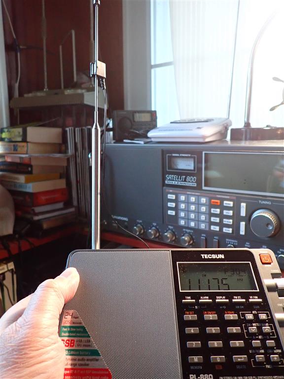
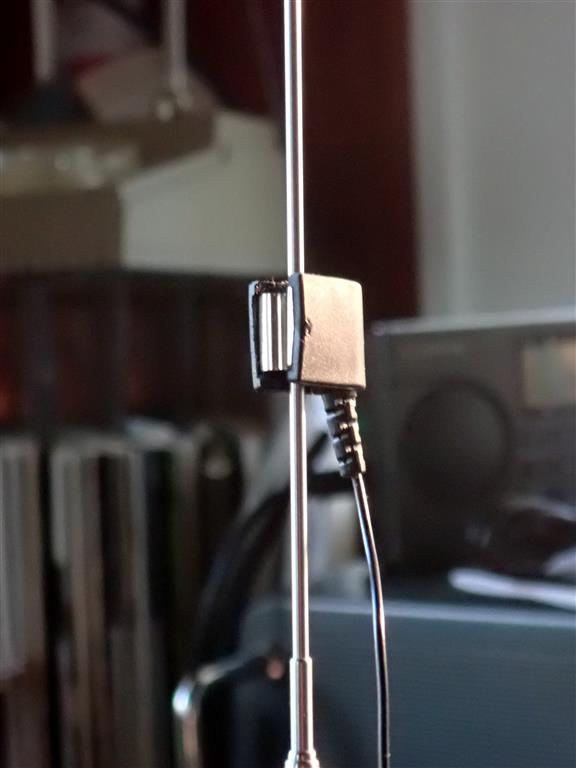
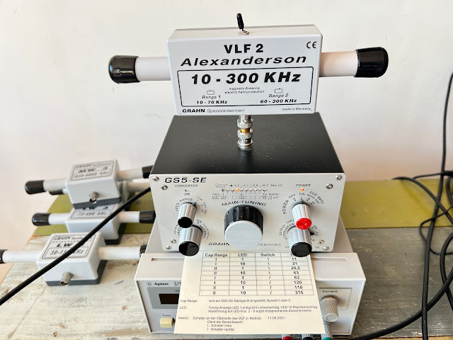
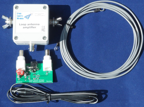
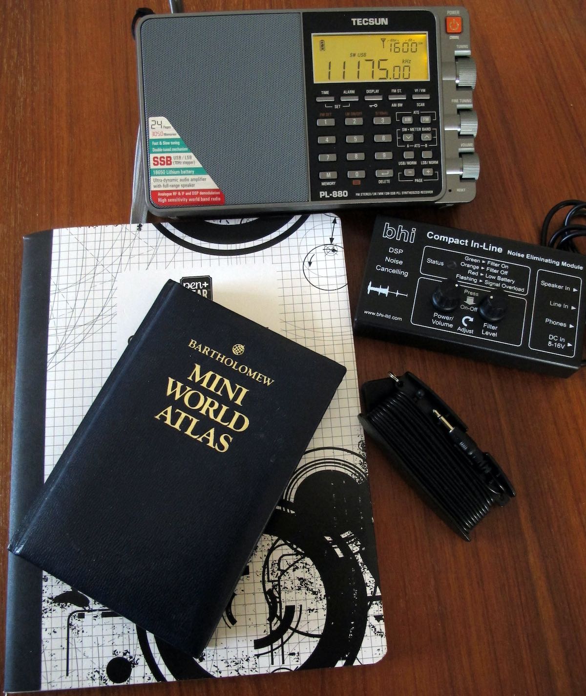
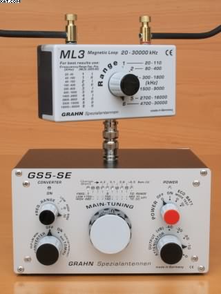
The Magic of Antennas (Nuts & Volts)
If you really want to know what makes any wireless application work, it is the antenna. Most people working with wireless — radio to those of you who prefer that term — tend to take antennas for granted. It is just something you have to add on to a wireless application at the last minute. Well, boy, do I have news for you. Without a good antenna, radio just doesn’t work too well. In this age of store/online-bought shortwave receivers, scanners, and amateur radio transceivers, your main job in getting your money’s worth out of these high-ticket purchases is to invest a little bit more and put up a really good antenna. In this article, I want to summarize some of the most common types and make you aware of what an antenna really is and how it works.
TRANSDUCER TO THE ETHER
In every wireless application, there is a transmitter and a receiver. They communicate via free space or what is often called the ether. At the transmitter, a radio signal is developed and then amplified to a specific power level. Then it is connected to an antenna. The antenna is the physical “thing” that converts the voltage from the transmitter into a radio signal. The radio signal is launched from the antenna toward the receiver.
A radio signal is the combination of a magnetic field and an electric field. Recall that a magnetic field is generated any time a current flows in a conductor. It is that invisible force field that can attract metal objects and cause compass needles to move. An electric field is another type of invisible force field that appears between conductors across which a voltage is applied. You have experienced an electric field if you have ever built up a charge by shuffling your feet across a carpet then touching something metal … zaaapp. A charged capacitor encloses an electric field between its plates.
Anyway, a radio wave is just a combination of the electric and magnetic fields at a right angle to one another. We call this an electromagnetic wave. This is what the antenna produces. It translates the voltage of the signal to be transmitted into these fields. The pair of fields are launched into space by the antenna, at which time they propagate at the speed of light through space (300,000,000 meters per second or about 186,000 miles per second). The two fields hang together and in effect, support and regenerate one another along the way. [Continue reading…]
Smith Chart Fundamentals (Nuts & Volts)
The Smith Chart is one of the most useful tools in radio communications, but it is often misunderstood. The purpose of this article is to introduce you to the basics of the Smith Chart. After reading this, you will have a better understanding of impedance matching and VSWR — common parameters in a radio station.
THE INVENTOR
The Smith Chart was invented by Phillip Smith, who was born in Lexington, MA on April 29, 1905. Smith attended Tufts College and was an active amateur radio operator with the callsign 1ANB. In 1928, he joined Bell Labs, where he became involved in the design of antennas for commercial AM broadcasting. Although Smith did a great deal of work with antennas, his expertise and passion focused on transmission lines. He relished the problem of matching the transmission line to the antenna; a component he considered matched the line to space. Continue reading