Tag Archives: Homebrew

Guest Post: Pavel’s Homebrew “Monster” Drain Pipe FSL Antenna


Many thanks to SWLing Post contributor, Pavel Kraus, for the following guest post:


Building a Drain Pipe FSL Antenna

by Pavel Kraus

Hi, I greet all DX fans and the entire SWLing Post community! I enjoy reading reading this blog and the diversity of contributions from our authors and contributors; many thanks from me for so much useful information.

The following are the construction notes of my FSL antenna, which I designed thanks to the suggestions of GaryDeBock, and other FSL designers.

The antenna is a classic design featuring 60 ferrite rods 200x 10 mm, which are placed on a plastic sewage pipe.

Pict 3: Pipe with ferrite rods and windings

Pict 4: Pipe with ferrite rods and windings

In addition, sewer pipe sections are used for the entire antenna cover. I assume that this material can be obtained in other countries as well. Continue reading

Spread the radio love

Giuseppe’s Homemade “Magic Tablet” Antenna System

Many thanks to SWLing Post contributor, Giuseppe Morlè, who writes:

Dear Thomas,

This is Giuseppe Morlè, from Formia central Italy on the Tyrrhenian Sea,

I built this “Magic Tablet. during a rainy afternoon to test various portables I have.

The tablet is composed of 2 separate circuits: one for the short waves, a single coil along the entire perimeter of the tablet, and another with 2 ferrites wrapped around 36 turns of telephone cable for the medium waves.

The heart of the system is a 1050 pf variable capacitor with its old wheel.

To listen to medium wave I have to exclude the short wave loop with a switch on the loop.

I also added another small switch to connect it to a capacitor for more or less capacity, but this I will do later.

I can test my portables like this because the tablet tunes very well from 500 kHz to 18 MHz. I spent very little to make all this as it is all recycled stuff.

You can see the first tests on the balcony of my house with a Tecsun H-501 via my YouTube channel:

Note: this video is in Italian, but you can turn on closed captions and have it translate into the language of your choice.

As I always say, I am not a technician and I have little manual skills in building things, not having a proper laboratory. When I get an idea, I put it on paper and I start to find all the materials and then see if they work. Not all of us are of the experts in electronics–what drives me is a passion for radio listening. Now being retired, I have more time to devote to it.

Thanks to you and hello to the whole SWLing Post community …

73. Giuseppe Morlè (IZ0GZW)

I love this, Giuseppe! What a clever all-in-one portable antenna system for your shortwave radios. I especially love the fact you were able to create all of this from parts you have at your home. You’ve got a winning attitude, too: build and experiment!  Thank you for sharing.

Spread the radio love

Loop-On-Ground Antenna Part 2: Tom upgrades his low profile, low noise, portable DXing antenna

Many thanks to SWLing Post contributor, TomL, who shares the following guest post:


Loop on Ground Part 2

by TomL

My previous Loop on Ground (LoG) experiment was useful which entailed connecting my Wellbrook loop amplifier to a 100 foot loop of speaker wire in the field at my favorite local Forest Preserve. It really brought in stations I had never heard before or strong stations in a more powerful way that made the audio really pleasant to listen to.  This report will describe more experiments with smaller wire loops to see what the limitations are.  100 feet of wire is quite a lot of wire to mess around with especially in the cold weather or public places that do not have as much private space.

I don’t understand all the electrical interrelationships but a long posting at RadioReference.com had  a great discussion about creating a 160-20 meters LoG receive-only antenna. It is 11 pages long but is worth reading how “nanZor” experimented with various parameters for general use. Kudos to him for documenting the findings as the design changed over time. You can find it here:

https://forums.radioreference.com/threads/160-20m-log-loop-on-ground.370110/

nanZor basically boils it down to a few guidelines.

  1. Keep it on the ground. Lifting the wire more than an inch or two decreased the lower angle signal reception greatly.
  2. Calculate the optimal length for one full wavelength of wire at the highest target frequency, say for example, the top of the 20 meter band (14350 kHz). 936/14.350 MHz * 0.9 velocity factor of simple insulated wire = 58.7 feet.  You can round up to 60 feet, no big deal since this is broadband.  The antenna should have a predictable reception pattern from 1/10th wavelength up to 1 full wavelength. Outside that range, the pattern gets “squirrely”.
  3. Using a 9:1 balun seemed to be a little better than a 4:1 balun at the antenna feedpoint. This gets into things I cannot measure and has to do with rising impedance as a loop gets closer to ground level. I am not sure but I think my Wellbrook amp has a built in 4:1 balun and it seems to work just fine.
  4. Make sure to use an RF Choke at BOTH sides of the feedline coax cable. He was adamant that the loop can get easily unbalanced and allow noise into the antenna and/or feedline and so it must be isolated and the ground allowed to “float” in his words.

Personally, I also wanted to use less wire and happened to have a length of 42 feet of landscape wire which should work well below 5 MHz with the Wellbrook amp engaged.  Results were not bad even though on hard frozen ground. Signal levels were down a little compared to the 100 foot of wire.  Here are a couple of examples, first one in a fast food parking lot with a grass field next to it and second at the usual Forest Preserve parking lot on a grass field.  I made sure that my car blocked the view of the wire so people would not get nervous!

La Voz Missionaria, Brazil:

Voice of Welt from Issoudun France in Kurdish:

These are not necessarily “DX” but definitely good for SWLing. I like the signal strength with the amplifier inline at the antenna feedpoint and I did not have to use an RF Choke at the receiver side as was suggested.

I had a 75 foot long insulated wire and used that at the Forest Preserve parking lot on a couple of different days.  Lower frequency signal strength and signal/noise ratio improved a little bit to be noticeable.

US Air Force HFGCS “numbers” station. Remote controlled from Andrews or Grand Forks bases (https://en.wikipedia.org/wiki/High_Frequency_Global_Communications_System), there was no way for me to know which of the 6 transmitters it was coming from:

BBC from Tinang Philippines in Korean:

Then, as nanZor suggested in his postings, I purchased a 9:1 balun/RF choke (it has both a balun and an RF choke built-in) from Ham Radio Outlet and put that in place of the Wellbrook amplifier.

I have not worked with it, but it is reported that the Nooelec.com v2 model is cheaper and works just as well – https://swling.com/blog/2019/10/the-nooelec-balun-19-v2/

Examples below with the 42 foot loop and 9:1 balun/choke, no amplifier:

KSDA, Agat Guam in English

WB8U doing a POTA activation of Leavenworth State Fishing Lake

VOLMET weather, Shannon Ireland

HCJB Quito Ecuador, probably in Quechua

As a side note, there is a posting that mentions low-angle DX is better with regions that have better “ground conductivity”, salt water being the best. I have no way of verifying this.  See post# 126 by KK5JY Matt.

So, bottom line is that a Loop on Ground can be useful for pleasant SWLing and portable.  Best to use it on grass, not asphalt.  The loop amplifier is useful to get signal levels up if you have to use a smaller loop size but the signal/noise ratio will suffer due to its smaller aperture.  And, warning, the public will find a way to trip over the wire no matter where you set it up (I may try putting the wire around my car if I can park on a grass surface and/or use the gaudiest, brightest neon green or orange wire I can find – they can’t trip over THAT, can they?).

TomL


Thanks, Tom, for sharing your update. Obviously, the LoG is working brilliantly. It’s amazing that you got such clear reception from the parking lot of a fast food restaurant.  If you were using a vertical instead, I bet signals would have been buried in the noise. 

I can also relate to people tripping over antenna wires. I remember one POTA activation recently (the first activation in this three park run) where I intentionally laid my counterpoise on the ground, off a foot path, in the brush and where I couldn’t imagine anyone ever stepping. Ten minutes into the activation and for no reason, someone walked off the path, into the brush, and it snagged them. Maybe I’m just a Ninja level trapper and never realized it!?

Thanks again for sharing the results of your LoG, Tom. Inspiring! 

Spread the radio love

Upgrading my Yaesu FT-817 transceiver with the G7UHN rev2 Buddy board

Last August, SWLing Post contributor, Andy (G7UHN), shared his homebrew project with us: a genius companion control display for the venerable Yaesu FT-817 general coverage QRP transceiver.

Andy’s article caused me (yes, I blame him) to wax nostalgic about the popular FT-817 transceiver. You see, I owned one of the first production models of the FT-817 in 2001 when I lived in the UK.

At the time, there was nothing like it on the market: a very portable and efficient HF, VHF, UHF, multi-mode general coverage QRP transceiver…all for $670 US.

In 2001? Yeah, Yaesu knocked it out of the ballpark!

In fact, they knocked it out of the ballpark so hard, the radio is still in production two decades later and in demand under the model FT-818.

I sold my FT-817 in 2008 to raise funds for the purchase of an Elecraft KX1, if memory serves. My reasoning? The one thing I disliked about my FT-817 was its tiny front-facing display. When combined with the embedded menus and lack of controls, it could get frustrating at home and in the field.

I mentioned in a previous post that I purchased a used FT-817ND from my buddy, Don, in October, 2020. I do blame Andy for this purchase. Indeed, I hereby declare him an FT-817 enabler!

FT-817 Buddy board

When I told Andy about my ‘817ND purchase, he asked if I’d like to help him test the FT-817 Buddy board versions. How could I refuse?

Andy sent me a prototype of his Version 2 Buddy board which arrived in late November. I had to source out a few bits (an Arduino board, Nokia display, and multi-conductor CAT cable). Andy kindly pre-populated all of the SMD components so I only needed to solder the Arduino board and configure/solder the cable. I did take a lot of care preparing and soldering the cable, making sure there was no unintentional short between the voltage and ground conductors.

Overall, I found the construction and programming pretty straight-forward. It helped that Andy did a remote session with me during the programming process (thanks, OM!). Andy is doing an amazing job with the documentation.

I do love how the board makes it easier to read the frequency and have direct access to important functions without digging through embedded menus. While there’s nothing stopping you from changing the program to suit you, Andy’s done a brilliant job with this since he’s an experienced FT-817 user.

The Nokia display is very well backlit, high contrast, and easy very to read.

“Resistance is futile”

I mentioned on Twitter that, with the backlight on, the FT-817 Buddy makes my ‘817ND look like it was recently assimilated by The Borg.

Don’t tell any Star Trek captains, but I’m good with that.

Andy has a rev3 board in the works and it sports something that will be a game-changer for me in the field: K1EL’s keyer chip!

For more information about the FT-817 Buddy, check out Andy’s website. At time of posting, it’s not available yet, but as Andy says, “it’s nearly there!”

Of course, we’ll keep you updated here as well. Many thanks to Andy for taking this project to the next level. No doubt a lot of FT-817 users will benefit from this brilliant project!

Spread the radio love

Tom builds a portable Loop-On-Ground antenna

Many thanks to SWLing Post contributor, TomL, who shares the following guest post:


My First Loop-On-Ground antenna

A number of people have mentioned the Loop On Ground (LOG) antenna in the past as a good receive-only antenna.  I did some research but could only find a few examples by amateur radio operators.

Matt Roberts (KK5JY) has a good article including some antenna theory and measurements, you can find it here:

http://www.kk5jy.net/LoG/ 

Someone named Tom (KG3V) has a write up on it but it is a little short on details:

https://kg3v.com/2020/01/04/loop-on-ground-the-simplest-receive-antenna-you-will-ever-build-and-it-works/

Stana Horzepa (WA1LOU) has something similar:

https://tapr.org/loop-on-ground-log-antenna/

I also read somewhere that for transmitting, a LOG antenna is useless as it radiates much of the energy right into the ground!  But I didn’t care about that.  I needed something for receive I can deploy easily without supports and take down just as easily.  As you may recall, my home condo is literally saturated with noise and I cannot null it out.  So a wire looped on the ground is supposed to work?  You bet it does!

Of course, there are some conditions to meet.  There has to be enough flat ground away from people or pets (or lawn mowers!) who would get tangled in the wire on the ground.  The wire should be as close to the ground as possible (although I had good results laying the wire on top of cut grass).  The loop of wire can vary in circumference from about 20 feet to 150 feet (the shorter length will stay in an omnidirectional pattern higher in frequency but lower in signal pickup and vice-versa for the longer length).  The wire needs to be insulated.  That’s about it!

So, off to the hardware store to buy a cheap spool of 100 foot 18 gauge speaker wire.  But, the articles mention using a balun and they all made their own.  I did not feel like doing that (I am not that good at making things from scratch) and I did not want to spend money ordering one. More reading somewhere informed me that my existing Wellbrook Medium Aperture loop amplifier has a built-in balun at the antenna side of the device.  Hallelujah!

I bundled together the wire, Wellbrook parts and battery supply, small laptop and Airspy HF+ to my favorite Lake Nelson Forest Preserve.  The shelter there is little used and is adjacent to the prairie with cut grass.  It did take a good 15 minutes to lay out the 100 feet of wire on the ground while trying to keep it as flat as possible. And I did not have enough space for a circle, so I ended up with an oblong shape.  The long sides are facing directly north-south, so in theory (I think) this gives me an oblong shaped reception pattern east-west.  The photo shows half of the wire laying on the grass.

I ended up with this setup on a picnic table at the rear end of the shelter.  The coax wire goes from the Wellbrook amp into its power module, then to a Cross Country Wireless preselector, then to the Apirspy HF+ and laptop.

I was really impressed by the signal strength of the usual suspects like Radio Nacional da Amazonia.  I could see that the Wellbrook amp was boosting signals across the board with only a little extra noise.

I use the preselector to try to keep the Airspy radio from overloading, especially mediumwave broadcast signals which can sound like a small amount of extra “hash” type noise in the background.  I have since added into the accessory chain an old Kiwa Electronics BCB filter that does a great job of knocking down the frequencies below 2 MHz.

I have also since added a water resistant box to enclose the Wellbrook amp to keep it safe from getting stepped on or too wet.

Also, a couple of weeks later I was able to go to a campgound and try out 60 feet of wire but the result was noisier since I was surrounded by RV vehicles in a crowded campsite.  It was not horrible and I was able to listen to some good radio stations but location can matter with any antenna.

I hope you like the recordings below.  Because of some serious health issues this summer, these May 31 2020 recordings & report are just being published now (I am recovering slowly but surely!).  My small laptop is under-powered, so I was only able to record MP3 files one at a time.  It kept me busy as I went from one frequency to the next and kept recording anything I heard.  I was able to hear a couple of stations I never heard before and that is a success in my book.

It remains to be seen if this antenna is as good as my 19 foot vertical antenna attached to the top of the car roof, especially low-angle DX signals.  Maybe you will have the chance to experiment as well and share your experience, too.  Now, will a small loop-on-ground antenna around my car parked late at night at a far corner of the grocery store work OK???  I will have to try it!

Recordings (crank up the volume if it is too weak):

22:00 UTC, Radio Saudi (Arabic) 11915 kHz

22:04 UTC, KDSA Adventist Radio (Indonesian) 11955 kHz

22:14 UTC, KDSA Adventist Radio (English) 12040 kHz

22:20 UTC, Voice of Korea (Japanese) 11865 kHz

22:23 UTC, Yemen Radio (heavily jammed) 11860 kHz

22:35 UTC, Radio Brazil Central (Portuguese) 11815 kHz

22:50 UTC, WWV booming in 10000 kHz

23:11 UTC, UnKnown (might be FEBC) 9795 kHz

23:15 UTC, China Radio Int’l (Spanish teaching Chinese, from Kashi) 9800 kHz

23:17 UTC, China Radio Int’l Business Radio (from Xianyang) 9820 kHz

23:19 UTC, China Radio Int’l (Chinese from Urumqi) 9865 kHz

23:21 UTC, Voice of Korea (Korean) 9875 kHz

23:23 UTC, Maybe Radio Taiwan without jamming from CNR 9900 kHz

23:34 UTC, China Radio Int’l (Chinese from Bamako Mali) 7295 kHz

23:43 UTC, Radio Nacional da Amazonia 6180 kHz (& 11780 kHz around 40 seconds)

23:50 UTC, MAYBE China PBS from Xinjiang in Kazakh (nothing else listed on schedules) 6015 kHz

23:56 UTC, Radio Mali (French announcer humming to music and acting crazy) 5995 kHz

00:07 UTC, Radio Rebelde (Spanish w/clear signal, Bauta, Cuba) 5025 kHz

00:15 UTC, 75 meter Amateur Radio 3913 kHz (LSB)

00:27 UTC, CHU Ottawa 3330 kHz

00:30 UTC, XEPPM Radio Educacion (Spanish Mexico City) 6185 kHz


This is brilliant Tom! Thank you for sharing. 

Our antenna guru contributor, Grayhat, has been encouraging me (understatement!) to build a Loop-On-Ground antenna but I haven’t done this yet because, at home, our driveway would interfere with its deployment. That and I have no RFI to speak of in my rural/remote home so my skyloop antenna is tough to beat. But having one available for portable use would make a lot of sense.  I’m going to put this on my 2021 project list!

Post Readers: Do you use a LoG antenna at home or in the field? Please comment!

Spread the radio love

How to build an automatic remote antenna switch


Many thanks to SWLing Post contributor, Kostas (SV3ORA), for sharing the following guest post which originally appeared on his radio website:


How to build an automatic rig/antenna switching system

by Kostas (SV3ORA)

When I started collecting vintage rigs, I ended up in a line of rigs on my bench, that were sitting there, disconnected from any mains cables or the antenna. I wanted these rigs to be ready to fire at any time I wanted to, without having to connect/disconnect cables all the time. I also wanted to be able to compare different rigs performances at the flip of a switch, which is the only way this can be done on the HF quick fading conditions. For power cables, the solution was to leave them connected in the mains plugs all the time. My rigs that have an internal PSU, have mechanical switches, so they are isolated from the mains when they are switched off. The rigs that are powered by an external PSU, depend on the external PSU main switch for isolation (in case they haven’t mechanical switches on them), which in my case is mechanical and switches off the mains power, when the PSU is switched off.

However, for the RF cables, this was a different story. Having only one antenna and multiple rigs, means that you have to connect each rig to the antenna every time you want to operate each rig. This is not only boring and time consuming (you have to reach the back of the transceivers to connect/disconnect the connectors), but eventually causes the connectors of the coaxial cable and the rigs to wear out. I decided to make things better and make an RF rig selector for my rigs. This RF rig selector has been described in this link.

The current antenna I use is fine for transmitting, but in the noisy neighbourhood where I live, it picks up a lot of noise. I have tried many solutions, without significant effect in the noise level. This is why I decided to use a separate antenna for receiving, from that used for transmitting. This antenna will be some kind of loop probably, so as to be immune to noise or insensitive to the direction of the noise. It will be placed in a different location than the transmitting antenna, a location which will be less noisy. Unfortunately, the space I have for the TX antenna lies in a very noisy location in my property. So a separate RX antenna, in another physical location is a must. This means that a separate coaxial for the RX antenna must be used. Thankfully, the RX coaxial can be very small in diameter, passing easily through the sides of the windows, without extra holes.

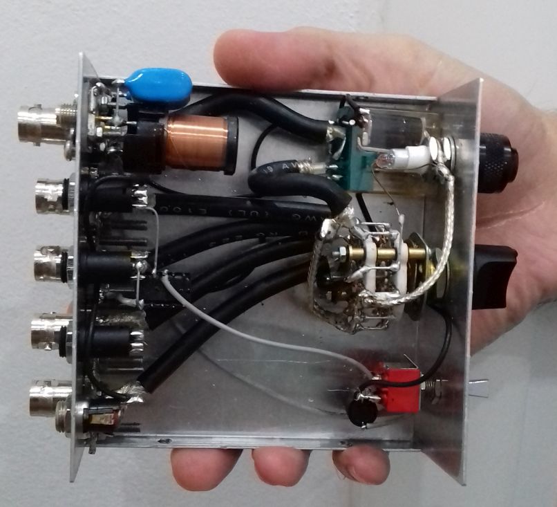
To satisfy all of my requirements, I developed the circuit shown above. The circuit is able to switch a common antenna to four different rigs. Why four? Because this was the capacity of my switch and the number of connectors I had available. If you have a greater capacity switch and more connectors, expand the circuit to your needs.

The circuit of the shack switch, allows for 4 separate rigs to be selected, and two antennas, one for RX and one for TX. TX/RX antenna selection is being done automatically (split antenna operation) and controlled by the PTT of any of the rigs connected. This feature can be bypassed by the switch, so that the TX antenna can be used for both RX and TX. The same switch allows also RX operation with passive RX antennas of active ones. When in the active RX antenna position, power is passed to the remote RX preamplifier through the RX coaxial cable, using a bias-T circuit. The values of the bias-T circuit have been chosen very large, so as active RX antennas that operate at LF and lower could still be used. The RF relay defaults in the TX antenna, so that if there is a power failure, or if the circuit is not supplied with power, you can still receive (and transmit) with the TX antenna. The other way around, would be fatal for both the transceiver and the RX antenna (If you transmitted accidentally into it).

The PTT circuits are based on my transceivers. Unfortunately, there is no “standard” for the PTT circuits, each rig has its own way, so the PTT circuits must be thought for each of them. I followed an “inhibit” approach for the PTTs. That is, all the PTT switches are connected in series and DC is passed through them. If any of the rigs transmits, the PTT switch is opened and the circuit switches to the TX antenna. For the rigs that do not have an internal relay but output DC on TX instead, an additional small relay is used (for greater isolation and lossless switching). The only drawback of this “inhibit” topology is that the PTTs of all the rigs must be connected to the circuit simultaneously. If you want to exclude a rig of course, you may short circuit it’s PTT connector in the circuit. The PTT circuits as I said, are non-standard, so you might want to change the circuit to your needs, but anyway you got the idea.

Notice the connections in the circuit. One section of the RF switch (on the left) is used for the positive wire (central conductor of the coaxial) and another for the negative (braid of the coaxial). Why is that? This is because I canted to add a special feature to the switch. That is, the ability to disconnect the antenna from any rig when the rigs are not used. Previously, I used to disconnect the antenna coaxial from the transceiver when I was away, so as to protect the transceiver from antenna static discharges and possibly destroy it’s front end circuits. Now, with a single flip of the switch, I am able to do so. Because I wanted the switch to operate on different types of antennas (balanced or not) I decided to short circuit both poles of the antenna at this position, to equalize their charges.

But equalizing their charges was not enough. I had to find a way to let these charges go to the ground, so that the antenna is discharged. Directly grounding the short circuit, did not seem a good thing to do, because the whole TX wire antenna on the roof would be grounded. Whether this is a good idea to avoid lightings or not, I do not know. So I decided to keep the short circuited antenna floating and instantly discharge it only when adequate static charge is built upon it. For this purpose, I used a neon tube, permanently connected to the switch NC (not-connected) position. When the switch is in the non-connected position, the tube lights up and discharges the antenna (both poles) if an appropriate amount of static charges has been built upon it. When the switch is in any of the selected rigs connections, the tube is disconnected, preventing it from lighting up when you transmit into the antenna. Note that this configuration, requires that the output (antennas) coaxial connectors must be isolated from the metal chassis of the RF switch!

Isolation of the output antenna connectors has been done with a PVC sheet and isolated screw rings. Also note the usage of BNC connectors on TX and SMA on RX. I used BNC connectors for various reasons. They are excellent connectors with quick lock/unlock features. You do not need to screw them (and wear them out) and once fit in place they are not unscrewed. Once fitted in place, they allow for rotating the connection without unscrewing the cable or bending it. They can handle 100W easily. Despite all these features, they are much smaller in size and lighter. Their reduced size fits easily to reduced diameter cables like the RG-58 and similar. In an RF switch where there are lots of cables connected, this does make a difference. They are also very common and very cheap. There are even types that do not require soldering at all to fit a coaxial to them. I use BNC connectors even at my antenna side, as they have been proven to be quite waterproof. The types of BNC connectors I choose are not silver plated. Despite silver plated connectors are better, in the long term they are corroded by humidity and become much worst than the nickel plated connectors. The connectors I used are nickel plated with gold plated central conductors. I have found these types to be much more durable over the years, despite being cheaper. The same goes for the RX SMA connector, but I used an SMA connector there so as to accommodate thinner coaxial cables for RX.

The BNC connectors used, are the square flange types. I used this type of connectors because when they are fitted onto the chassis, they cannot be unscrewed, unlike the single-hole types. For the RX though, I used an SMA connector because it is even smaller and it can accommodate smaller diameter cables. The coaxial cable used for the internal switch connections on TX, is the RG-223. This cable is silver-plated (both the central conductor and the braid), it has double braid for increased shielding, it is of the same diameter as the RG-58 and it has a bit lower loss. The cable loss is negligible though for such small pieces of cable. The same type of cable has been used for the internal switch-relay connections as well as for the connections of the selector to the rigs. Appropriate lengths of RG-223 cables were cut and fitted with BNC connectors at one side and the appropriate rig connectors at their other side. For the RX antenna, you may use the thinner diameter cable you can find. I used a small piece of very thin coaxial (taken out of the WiFi card of an old laptop) and passed this piece through the side of the windows of the shack and through the mosquito net of the windows. No extra holes are required that way! For the rest of the RX cable, you can use whatever cable diameter you want, but I tried to use the smallest diameter I could find, so that the cable is as much phantom as possible.

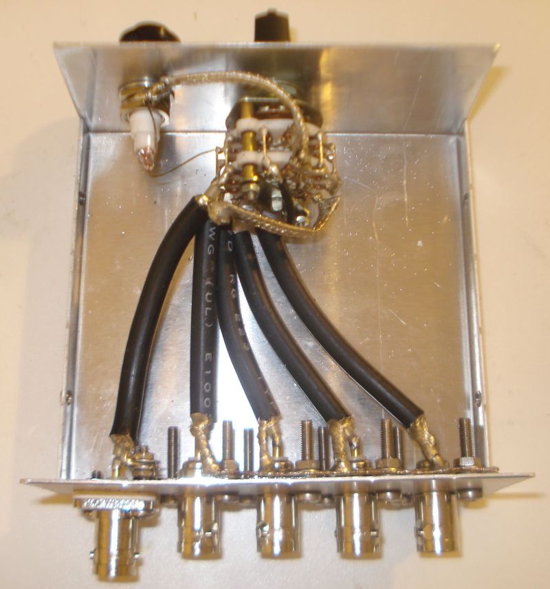
All the coaxial rig cables are grounded at the connectors side. I used a piece of coaxial braid and fitted it to the connectors screws. Then I soldered the braids of the coaxial cables onto this piece. Notice the black ring screw isolators at the antenna connector, to isolate it from the chassis. Speaking about the chassis, do not use a plastic chassis for the RF switch, use only a metal one! The picture below, as well as all the next pictures, show the RF cables arrangement, but note that the circuit in these pictures is not complete yet.

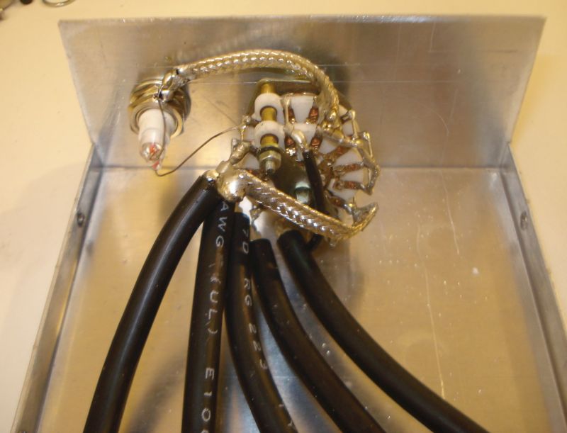
The coaxial cables are soldered onto the switch contacts. Where a ground connection is required, a piece of braid accomplishes this. Do not use thin wires, the device has to allow for at least 100W of HF RF power to pass through it. I have tested the switch with 200W of power and there were no problems at all. The neon tube directly connects to the appropriate switch contact and to the chassis.

The most important part of an RF switch is of course the switch itself. For 100W of HF RF power, I would suggest you to use a porcelain switch. I had a 5-positions 4-sections small porcelain switch, which I used. I connected two sections at each side in parallel (adjacent pins connected together). That is, two sections in parallel for the positive wire and two sections in parallel for the braid. I did that for various reasons. First, by using two contacts for each connection instead of one, you increase the power handling capability of the switch. Then, you ensure a sure-contact throughout the years. Any corrosion or wearing on the switch contacts would cause contact problems eventually. By using two contacts for each connection instead of one, you double the probability for a good contact. After all, I had a switch with more sections, so why not make a good use of them?

The completed selector is shown above. The relay was been taken out of an old CB radio. Use the best quality relay you can afford, as this will be switched quite often and it must handle at least 100W of RF power.

The results from the RF switch operation are quite satisfying. The overall construction is kept small and low profile. The switch makes a good contact despite being small. The automatic discharger seems to work well. On receive, there is some RF leakage, as I expected, in the near by cables, which is noticed in the higher HF bands or in very strong signals. The very sensitive receivers we use, are able to detect that. This RF leakage occurs even when the switch is in the NC position, where the antenna is disconnected and floating. So, to be honest I have not figured out if the leakage is from the switch or from the external cables in the shack. On TX, there is of course severe leakage from the transmitting coaxial to the rest of the ports. This IS expected. There is leakage even without using any selector at all, in the nearby receivers, when a transmitter operates at such high powers. There is nothing you can do about it really, unless your receiver has a mute capability, which I did not bother to take care of.

The TX/RX switching is taken care automatically and this is very useful and relaxing for the operator as he does not have to worry about anything. The active or passive RX antenna selector and the feature to disable the auxiliary RX antenna are really useful and you can do many antenna and rigs comparisons on-the-fly with it, by the flip of a switch. Depended on the noise level and the sensitivity you want to achieve, the switch will provide you the most optimal RX conditions instantly!

The most important thing though, is that the goal of this project was achieved. I am able to switch the antenna to whatever rig I want at the flip of a switch. And before I go away, at the flip of a switch I can isolate and automatically discharge the antenna when needed. This is so much more convenient than having to connect and disconnect cables all the time. I can also now use a separate antenna for RX, which greatly improves reception in my case. This antenna is automatically switched by any rig I have and I do not have to worry about anything. I can also do comparisons between different antennas on RX, which is crucial in deciding which antenna is better for receiving. All these features make this little simple to build circuit, so useful and an integral part of the shack.


Thank you for sharing this practical and affordable project with us, Kostas!

Post Readers: Check out this project and numerous others on Kostas’ excellent website.

Spread the radio love

Andy builds a genius companion control display for the Yaesu FT-817 transceiver

Many thanks to SWLing Post contributor, Andy Webster (G7UHN), who kindly shares the following guest post:


Yaesu FT-817 companion display

by Andy Webster (G7UHN)


Like so many I love getting out portable with my FT-817 but I do seem to spend so much of my operating time fiddling through the soft-keys because my most used functions (CW narrow filter, power and keyer settings to tune an ATU, A/B, A=B, etc.) are spread across different “pages” of the A,B,C assignments. Compared to the sublime experience of using my Elecraft K2 the FT-817 can be a little frustrating!

Last month, inspiration struck and I thought I could cobble together a small microcontroller and a little OLED display with some buttons to provide some extra soft-keys for the radio using the CAT serial port. Nothing particularly original here (I’ve seen articles of people using PICs for this purpose) but it seemed like a nice sized project for me to play with and build some experience doing PCBs (I’ve only done this once before at home). A little bit of discussion with Michael G0POT (FT-817 and SOTA guru), some Google searching and we were looking over KA7OEI’s excellent reference page (http://www.ka7oei.com/ft817_meow.html) and thinking about our favourite FT-817 commands…


As it happened I was lucky to have the right bits (Arduino Nano, small OLED display, buttons, prototype board and an 8-pin mini DIN cable) lying around the house to see “first light” from my FT-817’s serial port that evening. The Arduino Nano is a good place to start because it works at 5V so can work directly with the FT-817 levels on the ACC port. What followed next was some late nights of hacking on Arduino code to send and receive the data for my favourite commands and more experimentation on prototype board.

I tried a couple of cheap OLED displays and they look great indoors but weren’t quite up to the job in full sunlight which is fairly typical in my portable operations.

Daytime readability issues with an OLED display

By this point I had also realised the utility of having an auxiliary display on top of the radio as a much easier thing to view than the 817’s own display on the front panel. I’d also experienced some interference from the unshielded prototype board coming through as clicking sounds on the radio’s receiver so it looked as though some isolation between radio and my circuit might be necessary. Guided by many Internet tutorials, I switched to using a Nokia 5110-style LCD for better daylight readability and lower power consumption. Adding an ADUM1201 digital isolator and a B0505S-1W isolated DC-DC converter to the prototype board (modules acquired very quickly from eBay suppliers) gave me some isolation and lowered the interference which I guessed would disappear when I made the design on PCB with good ground planes around the signal lines.

Screen capture showing the schematic (click to enlarge)

With a (mostly) working prototype it was time to hammer the Internet tutorials again, this time to learn how to use KiCad, a free open-source PCB design tool available on Linux, Windows and Mac. I’ve done one PCB for home projects before using Autodesk EAGLE and I found learning Eagle pretty hard going, it seems like it carries 20 years worth of baggage and dogma in the user interface. In fact I started using EAGLE on this project but spent 3 hours on the first evening just trying to change the labels on the ADUM1201 chip that I couldn’t find in an EAGLE library… so I gave up and thought I’d try KiCad which I’d seen some recent good reports on. I’m happy to say after finding an excellent tutorial on KiCad I had drawn the schematic and my PCB layout in about 15 hours working time spread over a few evenings.

I should add that the 15 hours of KiCad time did include several hours of agonising over the choice of slide switch so a PCB can be done much quicker than that once you’ve got your favourite parts sorted!

That’s pretty impressive for my first go with KiCad as a near-beginner to PCBs, I heartily recommend it, it was so much easier than EAGLE and quite an enjoyable tool. Right, PCB design done and uploaded to JLCPCB for manufacture. 5 PCBs with DHL shipping cost me less than £20 and arrived from China within 5 calendar days. Other PCB fabs are available… 🙂

Click to enlarge

So that brings us to today, pretty much. The PCB was assembled very quickly (!) and there is no sign of noise from the serial data lines creeping into the 817’s receiver now it’s on PCB. Some lessons have been learned through the construction (e.g. brown 6mm push buttons are less “clicky” than the black ones and that’s a good thing!) and I now have my companion FT-817 display/buttons in field trials. I’ve no plans to sell this, it’s a trivially simple design, but it does make a great home project to polish your skills in microcontrollers, PCBs and construction. I’ll post a write-up on my website in due course.

In use, the device works just as I’d hoped, I can do everything I want to on my FT-817 without having to fiddle through the awkward button presses. The frequency display is also in a much better position for me now (as most FT-817 owners will know as they jealously eye the KX2, KX3, etc…!) and I think I used it for the whole session when I took it to the field on Saturday. If only my CW had been so slick!

Next steps are to work on the Arduino code. My code is pretty rubbish (my coding style involves a lot of Stack Overflow and copy/paste!) and not safe for public consumption. There are also some health warnings to be noted in manipulating the FT-817’s EEPROM (required for some of the functions I wanted), explained on KA7OEI’s page but there have been a few volunteers on Twitter to help with the software which is great. Also I may do a “Rev 2” board with an Arduino Pro Mini to lower the drain on the FT-817 battery before sharing the PCB files. Other than that it’s now time to get back outdoors and enjoy the new improved interface to my smallest radio! 😀

73
Andy G7UHN


Andy, I absolutely love this project! A wonderful addition to the FT-817/818 and I’d hardly call it a “trivial” design–!

I purchased the original FT-817 shortly after it was introduced. At the time, I was living in the UK and travelled extensively throughout Europe. I loved the ability to simply throw this little rig into my carryon and play radio pretty much anywhere my work travels took me. In the end, I did less ham radio work with the FT-817 and more SWLing.

Still, I eventually sold my FT-817 for the very same reason that motivated you to build a companion display: the front panel is too small and my most used functions require too much menu digging. 

Your companion board is an elegant homebrew solution. I love the Nokia LCD screen–superb readability in the field. 

Thank you again and once you do a write-up on for your website, we’ll be sure to link to it on the SWLing Post!


Do you enjoy the SWLing Post?

Please consider supporting us via Patreon or our Coffee Fund!

Your support makes articles like this one possible. Thank you!

Spread the radio love