Shortwave listening and everything radio including reviews, broadcasting, ham radio, field operation, DXing, maker kits, travel, emergency gear, events, and more
Many thanks to SWLing Post contributor, Steve Allen (KZ4TN), who shares the following guest post:
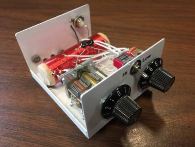
A Simple Antenna Tuner for SWL Radios
by Steve Allen, KZ4TN
After reading 13DKA’s excellent review of the Belka-DSP on SWLing.com a few weeks ago I knew I had to have one! The size, features, and performance of the Belka-DX (latest version of the Belka-DSP) is phenomenal. I won’t go into reviewing the radio as I couldn’t come close to 13DKA extensive review. If you are considering this SWL receiver his review is a must read.
I love bedtime SWLing and have been putting off setting up an outside antenna specifically to feed into the bedroom for too long. Given that the resonant frequency of the antenna would not be broad enough for the tuning range of the Belka-DX I decided to build a small antenna tuner just for SWLing.
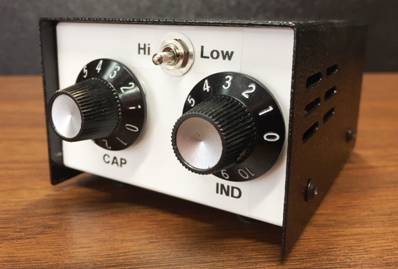
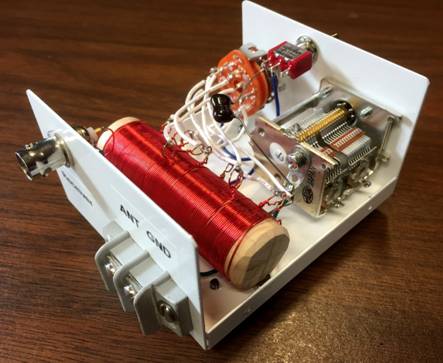
For the coil I wound ~100 turns of 26 Ga wire on a one inch diameter wooden dowel. The wire size can be whatever you have on hand. I twisted a tap every 10 turns. I drilled a hole in each end and glued in a machine screw to mount the coil to the bottom of the enclosure. I’ve had this enclosure in my junk box for a long time and have been waiting for just the right project. The variable capacitor I used was one I found on EBay a few years ago that had two sections, 330 pF and 120 pF. I tied them together for 450 pF. For the rotary switch I had to scratch around on eBay for a while until I found a 12 position single pole.
The plans for the tuner suggested adding a fixed value capacitor with a toggle switch to increase the lower end of the tuning range. I found a 510 pF silver mica and wired it into the circuit.
The antenna I put up is a sloper about 30 feet long.The high end is up about 40 feet and the low end is at about 12 feet. I put the antenna and tuner to the test last evening and the reception on the Belka-DX was superb. With the tuner the strength of the signal would peak about 2-3 units when I found the sweet spot.
The tuner also does double duty as an attenuator for very strong signals.
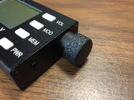
One mod I made to the Belka-DX was the addition of some grip tape to the tuning knob. It makes fine tuning much easier.
I believe we will continue to see a number of innovative receivers coming to market in the near term utilizing SDR technology. The ratio of performance to size of the Belka-DX is truly amazing in my opinion.
Thank you, Steve, for sharing this brilliant weekend project! As always, brilliant craftsmanship!
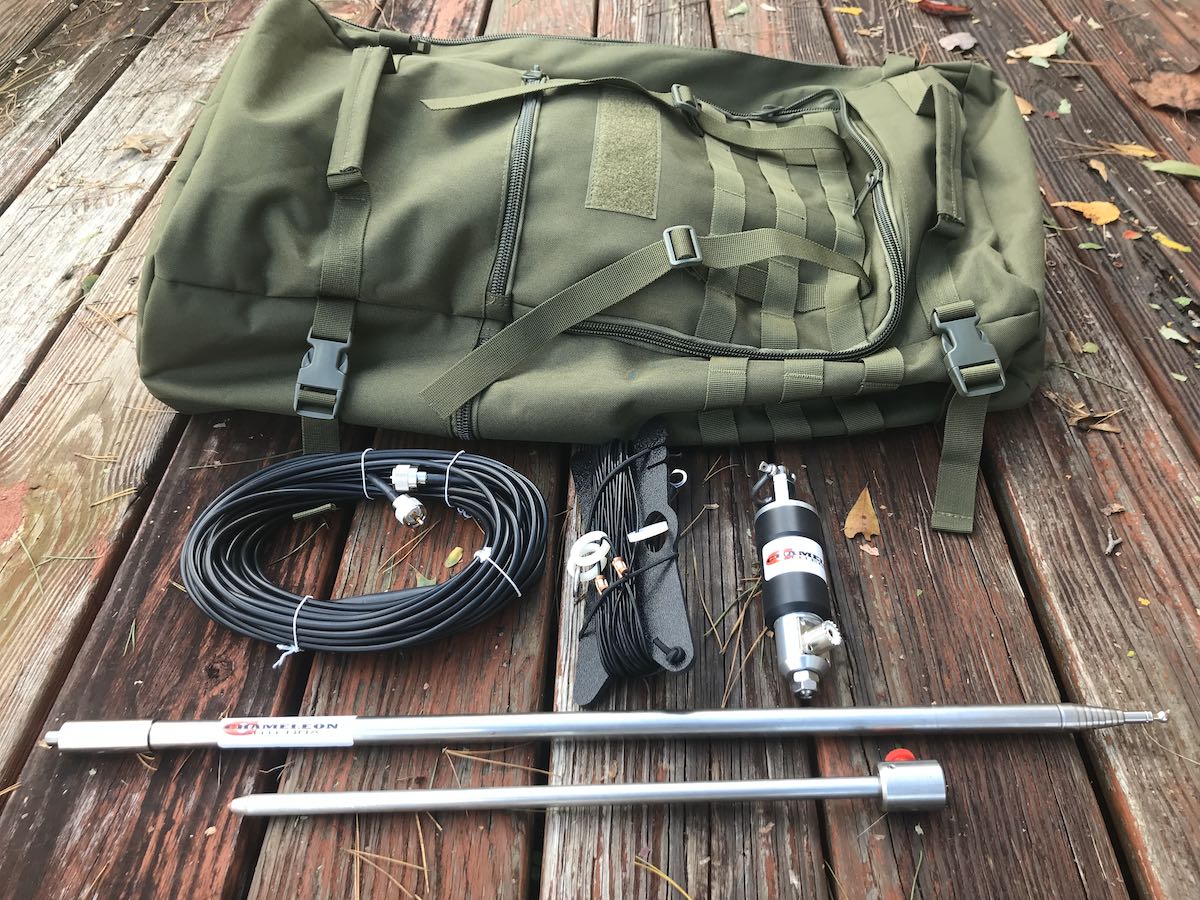
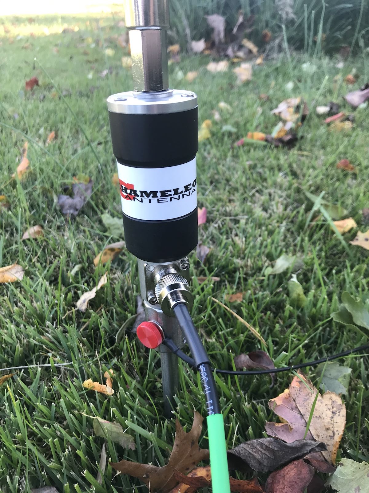
Chameleon Antenna recently sent me a prototype of their latest antenna: the CHA MPAS Lite.
The MPAS Lite is a compact version of their MPAS 2.0 modular antenna system and designed to be even more portable.
Chameleon Antenna is a specialist antenna manufacturer that makes military-grade, field portable antennas that are low-profile and stealthy. Chameleon products are 100% made in the USA and their customers range from amateur radio operators to the armed forces.
Their antennas are not cheap, but they are a prime example when we talk about “you pay for what you get.” In all of my years of evaluating radio products, I’ve never seen better quality field antennas–they’re absolutely top-shelf.
Zeta
I’m currently in my hometown doing a little caregiving for my parents. I’d only planned to be here for a couple of days, but when I saw that the remnants of Hurricane Zeta would pass directly over us with tropical storm force winds and rain, I stuck around to help the folks out.
Zeta struck quite a blow, in fact. No injuries reported, but over 23,000 of us have been without power for over 34+ hours in Catawba county. With saturated grounds, the winds toppled a lot of trees and damaged power lines.
Yesterday, I wanted to take advantage of the power outage and get on the air. I couldn’t really do a POTA activation because I needed to manage things here at my parents’ house. Plus, why not profit from the grid being down and bathe in a noise-free RF space–?
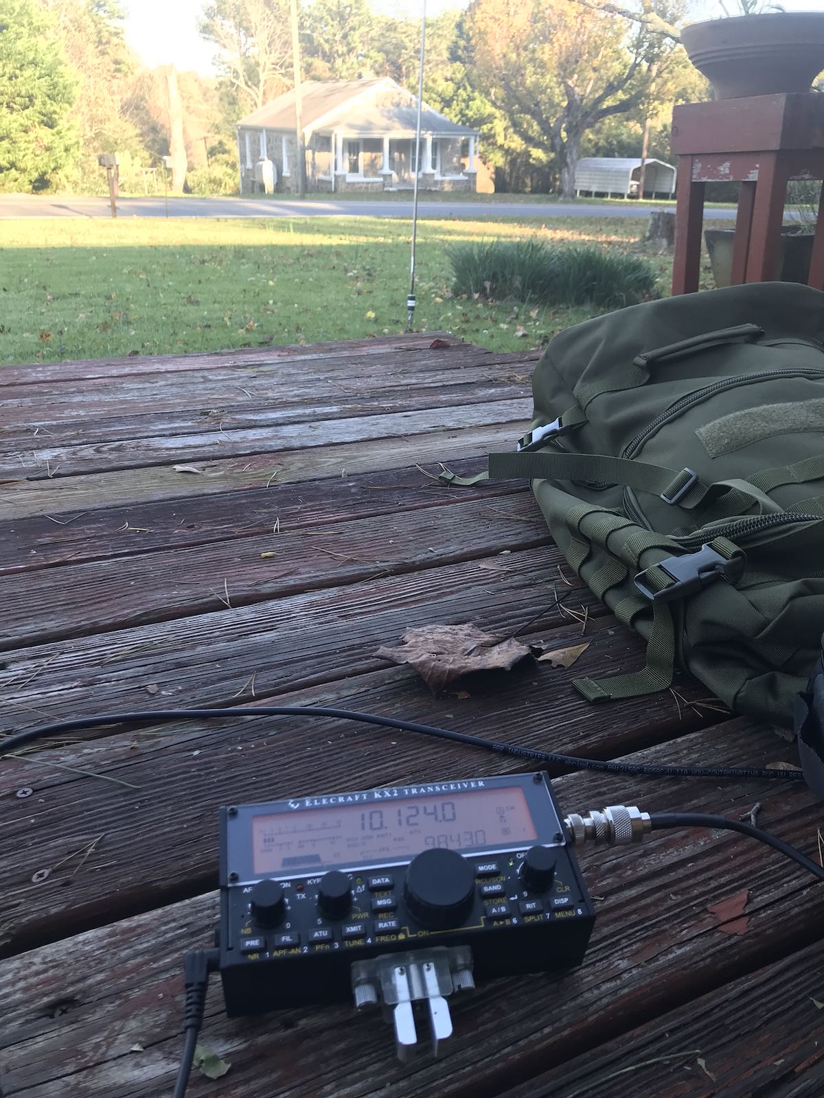
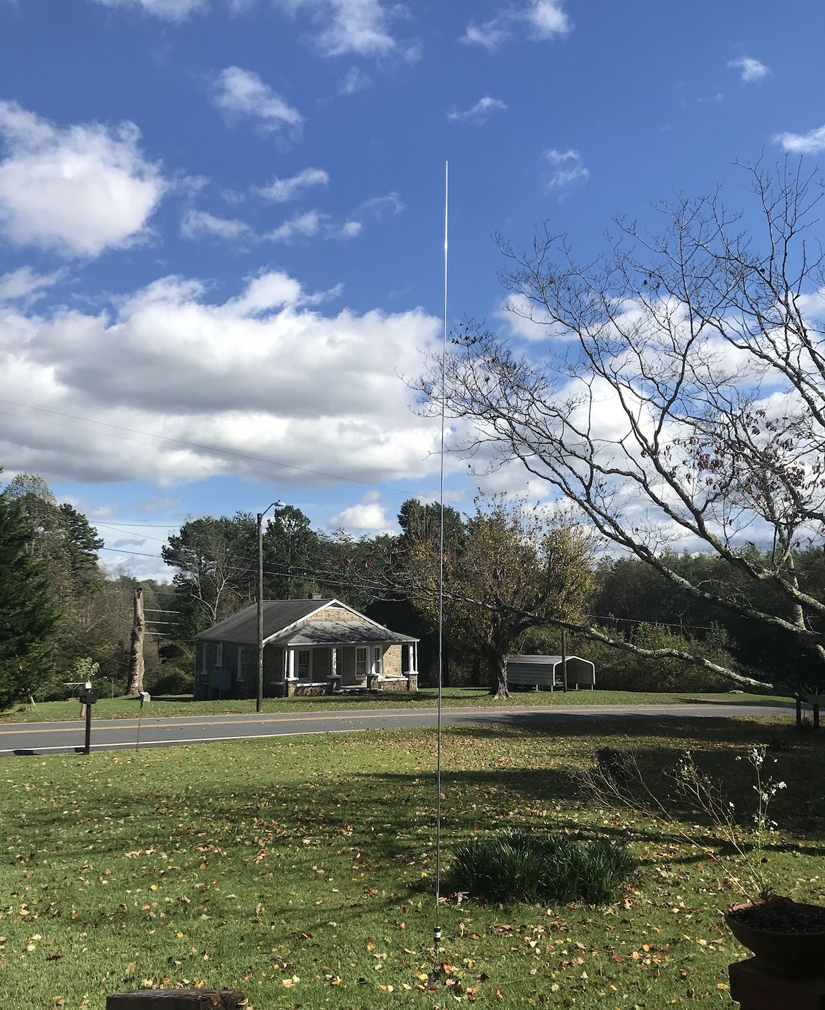
I decided to set it up in their front yard.
CHA MPAS Lite
I had never deployed the MPAS Lite before, so I did a quick scan through the owner’s manual. Although the MPAS Lite (like the MPAS 2.0) can be configured a number of ways, I deployed it as a simple vertical antenna.
Assembly was simple:
Insert the stainless steel spike in the ground,
Attach the counterpoise wire (I unraveled about 25′) to the spike
Screw on the CHA Micro-Hybrid
Screw the 17′ telescoping whip onto the Hybrid-Micro
Extend the whip antenna fully
Connect the supplied coax (with in-line choke) to the Hybrid-Micro
Connect the antenna to the rig
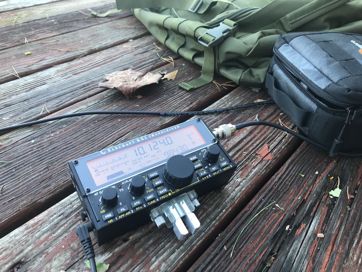
Although I had the Icom IC-705 packed, I wanted to keep things simple by using the Elecraft KX2 I’d also packed since it has a built-in ATU.
Important: the CHA MPAS Lite requires an ATU to get a good match across the bands.
I wasn’t in the mood to ragchew yesterday, but I thought it might be fun to see how easily I could tune the MPAS Lite from 80 meters up.
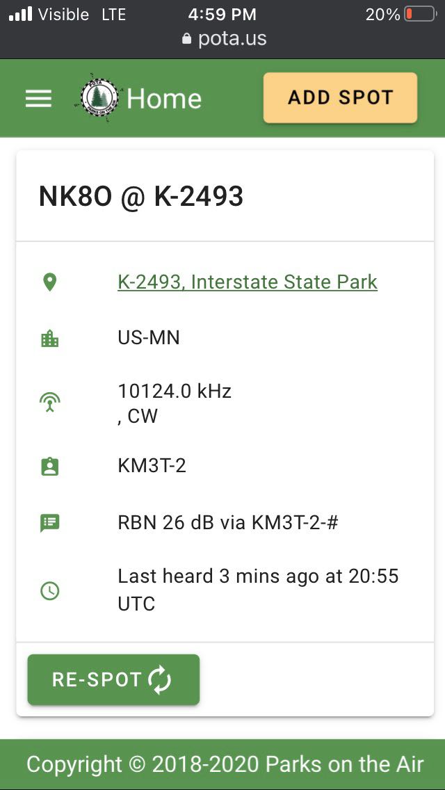
I checked the Parks On The Air spots page and saw NK8O activating a park in Minnesota in CW:
He was working a bit of a pile-up, but after three calls, he worked me and reported a 559 signal report. Not bad at 5 watts!
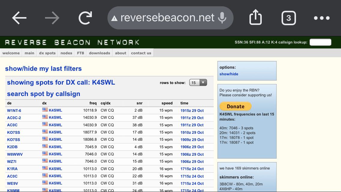
I then moved to 40, 18, and 20 meter and called CQ a couple times to see if the Reverse Beacon Network (RBN) could spot me. I like using the RBN to give me a “quick and dirty” signal report. I was very pleased with the bands I tested:
Those dB numbers are quite good for an op running 5 watts into a vertical compromised antenna.
The KX2 very effortlessly got near 1:1 matches on every band I tested.
Of course, after working a few stations in CW and SSB, I tuned to the broadcast bands and enjoyed a little RFI-free SWLing. Noting 13dka’s recent article, I’m thinking on the coast, the MPAS Lite will make for a superb amateur radio and SWLing antenna.
Durability
Although the remnants of Zeta had effectively passed through the area three hours prior, it was still very blustery outside. I was concerned gusts might even be a little too strong for the 17′ whip, but I was wrong. The whip handled the wind gusts with ease and the spike held it in place with no problem.
One of the things I have to watch with my Wolf River Coils TIA vertical is the fact it’s prone to fall in windy conditions and many ops have noted that this can permanently damage the telescoping whip (the weak point in that system).
I’m pretty certain this wouldn’t happen with the Chameleon 17′ whip–it feels very substantial and solid.
Ready to hit the field with the CHA MPAS Lite!
I’m a huge fan of wire antennas because I believe they give me the most “bang-for-buck” in the field, but they’re not always practical to deploy. I like having a good self-supporting antenna option in my tool belt when there are no trees around or when parks don’t allow me to hang antennas in their trees.
I’ve got a park in mind that will make for a good test of the CHA MPAS Lite: it’s a remote game land with no real parking option. I’ll have to activate it on the roadside–an ideal application for the MPAS Lite.
Many thanks to SWLing Post contributor, 13dka, who shares the following guest post:
Gone fishing…for DX: Reception enhancement at the seaside
by 13dka
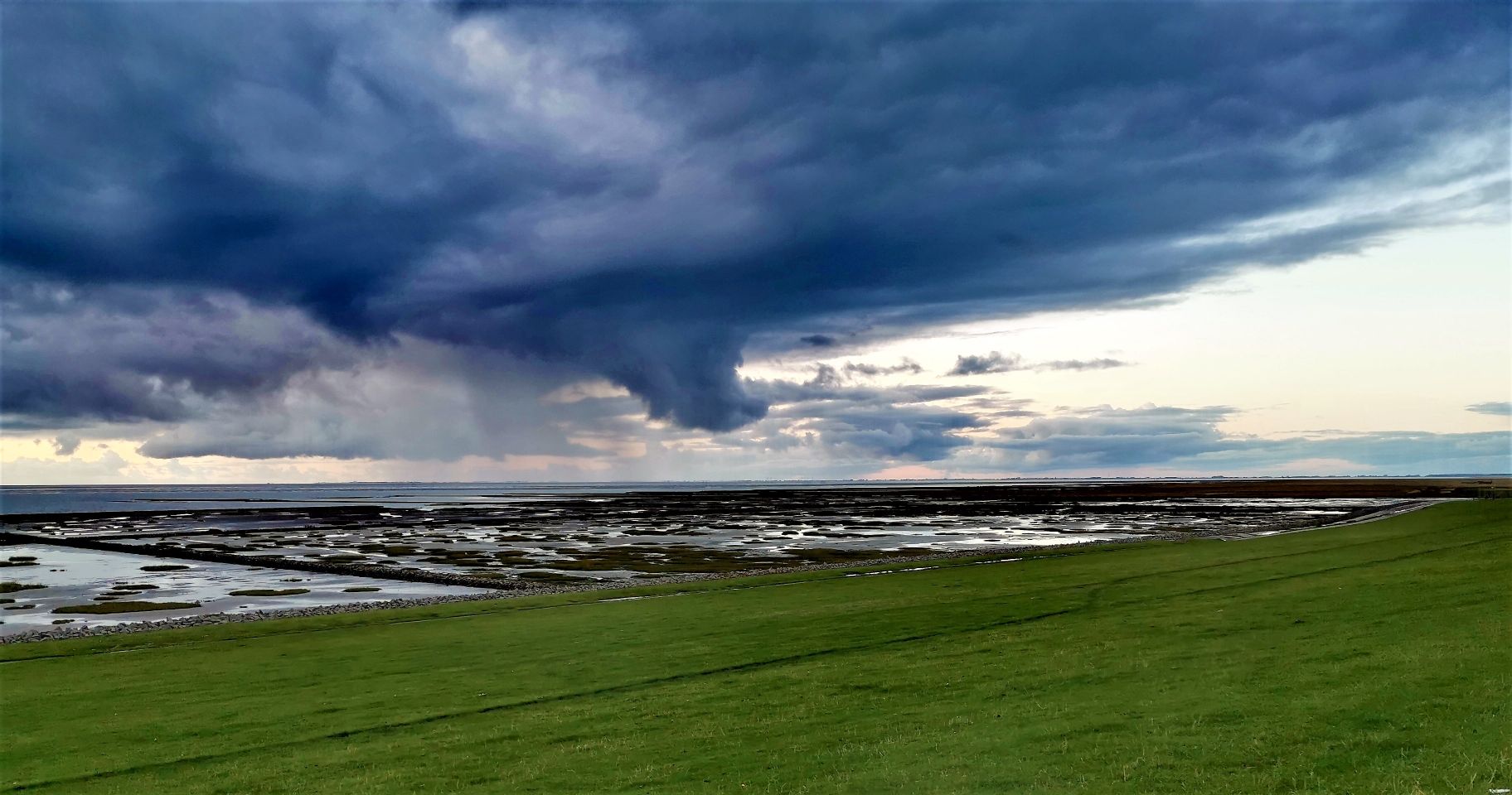
In each of my few reviews I referred to “the dike” or “my happy place”, which is a tiny stretch of the 380 miles of dike protecting Germany’s North Sea coast. This is the place where I like to go for maximum listening pleasure and of course for testing radios. Everyone knows that close proximity to an ocean is good for radio reception…but why is that? Is there a way to quantify “good”?
Of course there is, this has been documented before, there is probably lots of literature about it and old papers like this one (click here to download PDF). A complete answer to the question has at least two parts:
1. Less QRM
It may be obvious, but civilization and therefore QRM sources at such a place extend to one hemisphere only, because the other one is covered with ocean for 100s, if not 1000s of miles. There are few places on the planet that offer such a lack of civilization in such a big area, while still being accessible, habitable and in range for pizza delivery. Unless you’re in the midst of a noisy tourist trap town, QRM will be low. Still, you may have to find a good spot away from all tourist attractions and industry for absolutely minimal QRM.
My dike listening post is far enough from the next small tourist trap town (in which I live) and also sufficiently far away from the few houses of the next tiny village and it’s located in an area that doesn’t have HV power lines (important for MW and LW reception!) or industrial areas, other small villages are miles away and miles apart, the next town is 20 km/12 miles away from there. In other words, man-made noise is just not an issue there.
That alone would be making shortwave reception as good as it gets and it gives me an opportunity to check out radios on my own terms: The only way to assess a radio’s properties and qualities without or beyond test equipment is under ideal conditions, particularly for everything that has to do with sensitivity. It’s already difficult without QRM (because natural noise (QRN) can easily be higher than the receiver’s sensitivity threshold too, depending on a number of factors), and even small amounts of QRM on top make that assessment increasingly impossible. This is particularly true for portables, which often can’t be fully isolated from local noise sources for a couple of reasons.
Yes, most modern radios are all very sensitive and equal to the degree that it doesn’t make a difference in 98% of all regular reception scenarios but my experience at the dike is that there are still differences, and the difference between my least sensitive and my most sensitive portable is not at all negligible, even more because they are not only receivers but the entire receiving system including the antenna. You won’t notice that difference in the middle of a city, but you may notice it in the woods.
When the radio gets boring, I can still have fun with the swing and the slide!
2. More signal
I always had a feeling that signals actually increase at the dike and that made me curious enough to actually test this by having a receiver tuned to some station in the car, then driving away from the dike and back. Until recently it didn’t come to me to document or even quantify this difference though. When I was once again googling for simple answers to the question what the reason might be, I stumbled upon this video: Callum (M0MCX) demonstrating the true reason for this in MMANA (an antenna modeling software) on his “DX Commander” channel:
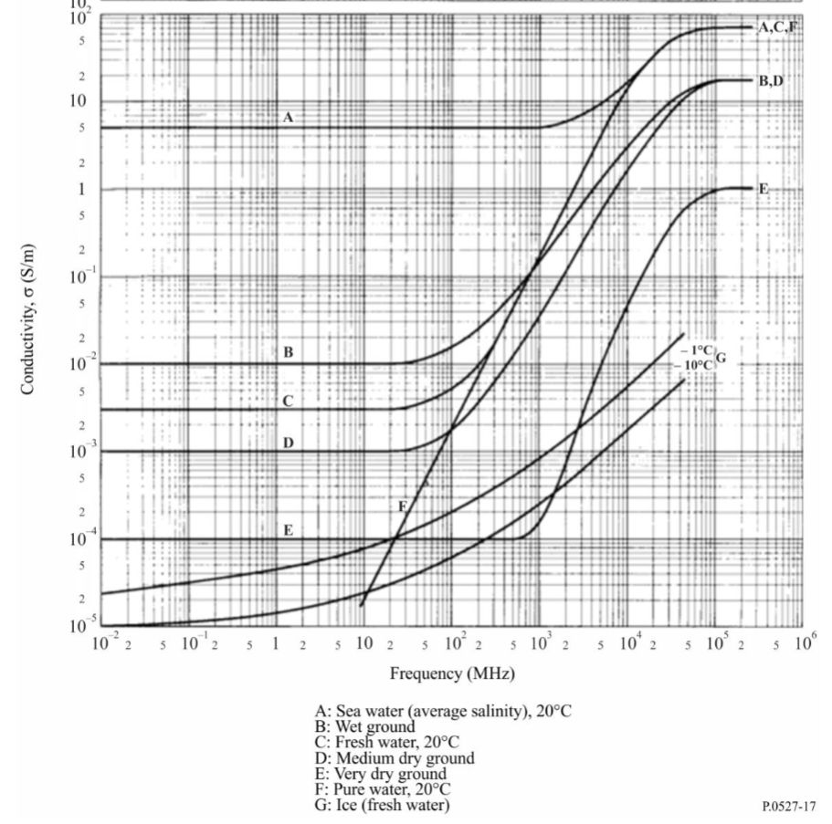
To summarize this, Callum explains how a pretty dramatic difference in ground conductivity near the sea (click here to download PDF) leads to an increase in antenna gain, or more precisely a decrease in ground return losses equaling more antenna gain. Of course I assumed that the salt water has something to do with but I had no idea how much: For example, average ground has a conductivity of 0.005 Siemens per meter, salt water is averaging at 5.0 S/m, that’s a factor of 1,000 (!) and that leads to roughly 10dB of gain. That’s right, whatever antenna you use at home in the backcountry would get a free 10dB gain increase by the sea, antennas with actual dBd or dBi gain have even more gain there.
That this has a nice impact on your transmitting signal should be obvious if you’re a ham, if not just imagine that you’d need a 10x more powerful amplifier or an array of wires or verticals or a full-size Yagi to get that kind of gain by directionality. But this is also great for reception: You may argue that 10dB is “only” little more than 1.5 S-units but 1.5 S-units at the bottom of the meter scale spans the entire range between “can’t hear a thing” and “fully copy”!
A practical test
It’s not that I don’t believe DX Commander’s assessment there but I just had to see it myself and find a way to share that with you. A difficulty was finding a station that has A) a stable signal but is B) not really local, C) on shortwave, D) always on air and E) propagation must be across water or at least along the coastline.
The army (or navy) to the rescue! After several days of observing STANAG stations for their variation in signal on different times of the day, I picked one on 4083 kHz (thanks to whoever pays taxes to keep that thing blasting the band day and night!). I don’t know where exactly (my KiwiSDR-assisted guess is the English channel region) that station is, but it’s always in the same narrow range of levels around S9 here at home, there’s usually the same little QSB on the signal, and the signals are the same day or night.
On top of that, I had a look at geological maps of my part of the country to find out how far I should drive into the backcountry to find conditions that are really different from the coast. Where I live, former sea ground and marsh land is forming a pretty wide strip of moist, fertile soil with above average conductivity, but approximately 20km/12mi to the east the ground changes to a composition typical for the terminal moraine inland formed in the ice age. So I picked a quiet place 25km east of my QTH to measure the level of that STANAG station and also to record the BBC on 198 kHz. Some source stated that the coastal enhancement effect can be observed within 10 lambda distance to the shoreline, that would be 730m for the 4 MHz STANAG station and 15km for the BBC, so 25km should suffice to rule out any residue enhancement from the seaside.
My car stereo has no S-meter (or a proper antenna, so reception is needlessly bad but this is good in this case) so all you get is the difference in audio. The car had the same orientation (nose pointing to the east) at both places. For the 4 MHz signal though (coincidence or not), the meter shows ~10dBm (or dBµV/EMF) more signal at the dike.
3. Effect on SNR
Remember, more signal alone does not equal better reception, what we’re looking for is a better signal-to-noise ratio (SNR). Now that we’ve established that the man-made noise should be as low as possible at “my” dike, the remaining question is: Does this signal enhancement have an effect on SNR as well? I mean, even if there is virtually no local QRM at my “happy place” – there is still natural noise (QRN) and wouldn’t that likely gain 10dB too?
Here are some hypotheses that may be subject of debate and some calculations way over my head (physics/math fans, please comment and help someone out who always got an F in math!). Sorry for all the gross oversimplifications:
Extremely lossy antennas
We know that pure reception antennas are often a bit different in that the general reciprocity rule has comparatively little meaning, many antennas designed for optimizing reception in specific situations would be terrible transmitting antennas. One quite extreme example, not meant to optimize anything but portability is the telescopic whip on shortwaves >10m. At the dike, those gain more signal too. When the QRN drops after sunset on higher frequencies, the extremely lossy whip might be an exception because the signal coming out of it is so small that it’s much closer to the receiver noise, so this friendly signal boost could lift very faint signals above the receiver noise more than the QRN, which in turn could mean a little increase in SNR, and as we know even a little increase in SNR can go a long way.
The BBC Radio 4 longwave recording is likely another example for this – the unusually weak signal is coming from a small and badly matched rubber antenna with abysmal performance on all frequency ranges including LW. The SNR is obviously increasing at the dike because the signal gets lifted more above the base noise of the receiving system, while the atmospheric noise component is likely still far below that threshold. Many deliberately lossy antenna design, such as flag/tennant, passive small aperture loops (like e.g. the YouLoop) or loop-on-ground antennas may benefit most from losses decreasing by 10dB.
Not so lossy antennas, polarization and elevation patterns
However, there is still more than a signal strength difference between “big” antennas and the whips at the dike: Not only at the sea, directionality will have an impact on QRN levels, a bidirectional antenna may already decrease QRN and hence increase SNR further, an unidirectional antenna even more, that’s one reason why proper Beverage antennas for example work wonders particularly on noisy low frequencies at night (but this is actually a bad example because Beverage antennas are said to work best on lossy ground).
Also, directional or not, the “ideal” ground will likely change the radiation pattern, namely the elevation angles, putting the “focus” of the antenna from near to far – or vice versa: As far as my research went, antennas with horizontal polarization are not ideal in this regard as they benefit much less from the “mirror effect” and a relatively low antenna height may be more disadvantageous for DX (but maybe good for NVIS/local ragchewing) than usual. Well, that explains why I never got particularly good results with horizontal dipoles at the dike!
Using a loop-on-ground antenna at a place without QRM may sound ridiculously out of place at first, but they are bidirectional and vertically polarized antennas, so the high ground conductivity theoretically flattens the take-off angle of the lobes, on top of that they are ~10dB less lossy at the dike, making even a LoG act more like something you’d string up as high as possible elsewhere. They are incredibly convenient, particularly on beaches where natural antenna supports may be non-existent and I found them working extremely well at the dike, now I think I know why. In particular the preamplified version I tried proved to be good enough to receive 4 continents on 20m and a 5th one on 40m – over the course of 4 hours on an evening when conditions were at best slightly above average. Though the really important point is that it increased the SNR further, despite the QRN still showing up on the little Belka’s meter when I connected the whip for comparison (alas not shown in the video).
The 5th continent is missing in this video because the signals from South Africa were not great anymore that late in the evening, but a recording exists.
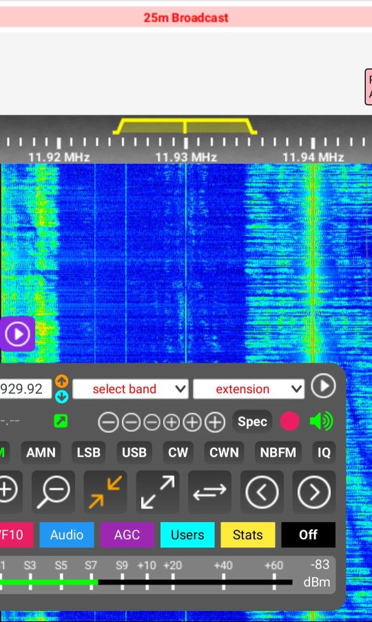
Here’s a video I shot last year, comparing the same LoG with the whip on my Tecsun S-8800 on 25m (Radio Marti 11930 kHz):
At the same time, I recorded the station with the next decent (but more inland) KiwiSDR in my area:
Of course, these directionality vs noise mechanisms are basically the same on any soil. But compensating ground losses and getting flat elevation patterns may require great efforts, like extensive radial systems, buried meshes etc. and it’s pretty hard to cover enough area around the antenna (minimum 1/2 wavelength, ideally more!) to get optimum results on disadvantaged soils, while still never reaching the beach conditions. You may have to invest a lot of labor and/or money to overcome such geological hardships, while the beach gives you all that for free.
But there may be yet another contributing factor: The gain pattern is likely not symmetrical – signals (and QRN) coming from the land side will likely not benefit the same way from the enhancement, which tapers off quickly (10 wavelengths) on the land side of the dike and regular “cross-country” conditions take place in that direction, while salt water stretching far beyond the horizon is enhancing reception to the other side.
So my preliminary answer to that question would be: “Yes, under circumstances the shoreline signal increase and ground properties can improve SNR further, that improvement can be harvested easily with vertically polarized antennas”.
Would it be worthwhile driving 1000 miles to the next ocean beach… for SWLing?
Maybe not every week–? Seriously, it depends.
Sure, an ocean shoreline will generally help turning up the very best your radios and antennas can deliver, I think the only way to top this would be adding a sensible amount of elevation, a.k.a. cliff coasts.
If you’re interested in extreme DX or just in the technical performance aspect, if you want to experience what your stuff is capable of or if you don’t want to put a lot of effort into setting up antennas, you should definitely find a quiet place at the ocean, particularly if your options to get maximum performance are rather limited (space constraints, QRM, HOA restrictions, you name it) at home.
If you’re a BCL/program listener and more interested in the “content” than the way it came to you, if you’re generally happy with reception of your favorite programs or if you simply have some very well working setup at home, there’s likely not much the beach could offer you in terms of radio. But the seaside has much more to offer than fatter shortwaves of course.
From left to right: Starry sky capture with cellphone cam, nocticlucent clouds behind the dike, car with hot coffee inside and a shortwave portable suction-cupped to the side window – nights at the dike are usually cold but sometimes just beautiful. (Click to enlarge.)
However, getting away from the QRM means everything for a better SNR and best reception. In other words, if the next ocean is really a hassle to reach, it may be a better idea to just find a very quiet place nearby and maybe putting up some more substantial antenna than driving 1000 miles. But if you happen to plan on some seaside vacation, make absolutely sure you bring two radios (because it may break your heart if your only radio fails)!
A little update (2023):
Like I said, the +10dB signal boost works both ways and here’s a nice example that I thought should be here. This is W4SWV, literally standing with both feet in the Atlantic ocean at the South Carolina coastline, carrying a 25W backpack radio with a whip and talking to F6ARC in France on 17m – received at my side of the pond using my simple vertical 33’/10m monopole antenna at the dike:
This was recorded on July 4th, 2021 and does not provide a reference to demonstrate how good or bad this is of course, all you have is my word that getting such a solid and loud signal from a 25W station on the US East Coast was just outstanding (compared to a fair number of coastal QRP stations I copied at the dike over the years, or the average 100W inland stations).
Meanwhile I found out that I’m luckily not the only (or the first) person who tried to make some practical experiments to reassess the theories in recent times: Greg Lane (N4KGL) made measurements by transmitting a WSPR signal simultaneously off 2 locations, one near the shoreline and one more inland. Measuring the signals created in distant WSPR receivers, he got similar results. He made a presentation about it in 2020:
Since I mentioned it, here is a pic of the antenna showing its installation:
Click images to enlarge.
In the above image you can see the overall setup of the LLD, the modification I did, by adding additional wires to the end of the arms and also the Mini Whip location
The LLD served me well, from LW up to around 200MHz allowing me to listen to broadcasters, hams, aircraft communications, time signals and then more, and it’s definitely a keeper, but I wanted to give a try to the “Mini Whip” antenna, even if a lot of people discard it saying it’s a noisy antenna and not worth it; keep in mind the Utwente SDR uses it and it seems to work fine, so I had to give it a try !
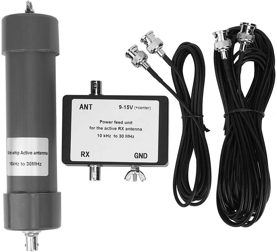
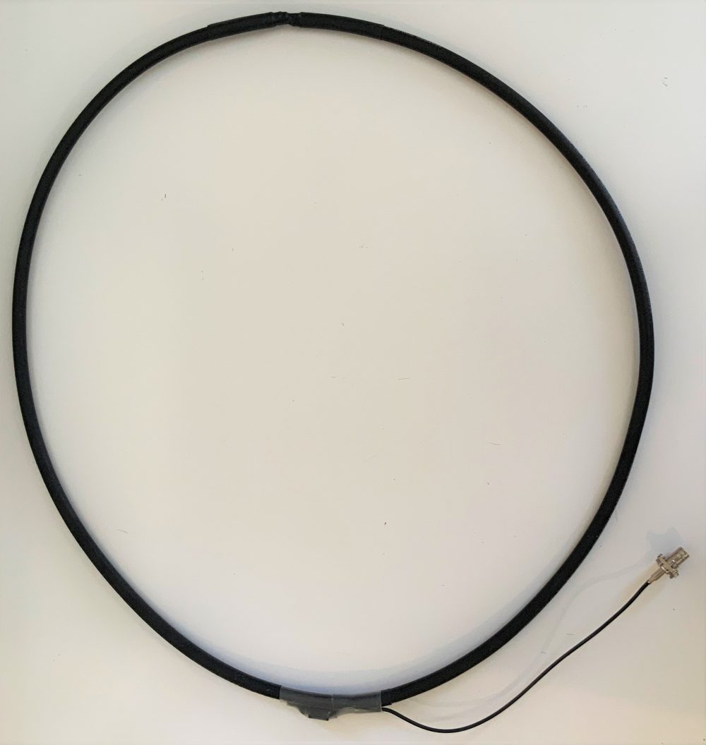
Anyhow, after searching the internet for a suitable whip, I finally found this one:
I bought the antenna on Amazon, but it’s also available on eBay and while the price isn’t the lowest one, I chose it since it uses BNC connectors only (some models use a mix of UHF/BNC or the like). This one had a top wing nut allowing to connect an additional (optional) external whip (may be useful on lower bands) and, last but not least, its color; being gray, it is quite stealth, which may be useful for some people (not my case, luckily). So I went on and ordered the antenna, the delivery took about 10 days and the package contents were exactly as shown above. The supplied coax is thin (RG-174 I believe) and it would be a good idea replacing it with some runs of RG-58, but for the sake of the experiment, I used the original wire.
So, having the antenna, I looked around for informations about the correct installation for the “Mini Whip” and found that in most cases, the reported poor performances of the Mini Whip are due to people installing it the wrong way. For reference and information about how the whip works and about how to properly install it, please refer to the information from PA3FWM found here and here.
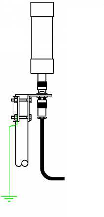
Now, if you can place the whip in a garden or yard, using a pole, the correct installation of the whip is the one shown in this pic:
If you carefully look at the image you will notice that the whip sits above the supporting (metallic) pole and that the ground of the connector is electrically connected to the pole (through the clamp). Plus, the pole is then grounded (at the bottom) and the coax (which has chokes) runs away from the metallic pole.
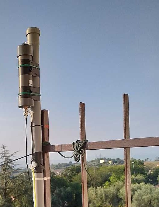
What does the above mean ? Well, the Mini Whip antenna needs a “counterpoise” (ground) to work, and installing it as above, instead of using the coax braid as its counterpoise, the Mini Whip will use the supporting pole, this helps a lot minimizing the noise and it’s one of the tricks for a proper setup, the other one is placing the whip as far away from the “noise cloud” of your home as possible. In my case, I choose the far end of the balcony–also since I had a nice support there, the image below shows the whip installation using a piece of PVC pipe I bought at a nearby home improvement store:
At first, I just installed the antenna without the ground wire and with the coax coming down vertically from the connector. When I compared the whip to my LLD, the results were discouraging: the noise floor was much higher and a lot of signals, which the LLD received without problems, totally disappeared inside the noise floor.
Being the kind of hard-headed guy I am (and having read the documentation about proper setup) I went on and made further modifications.
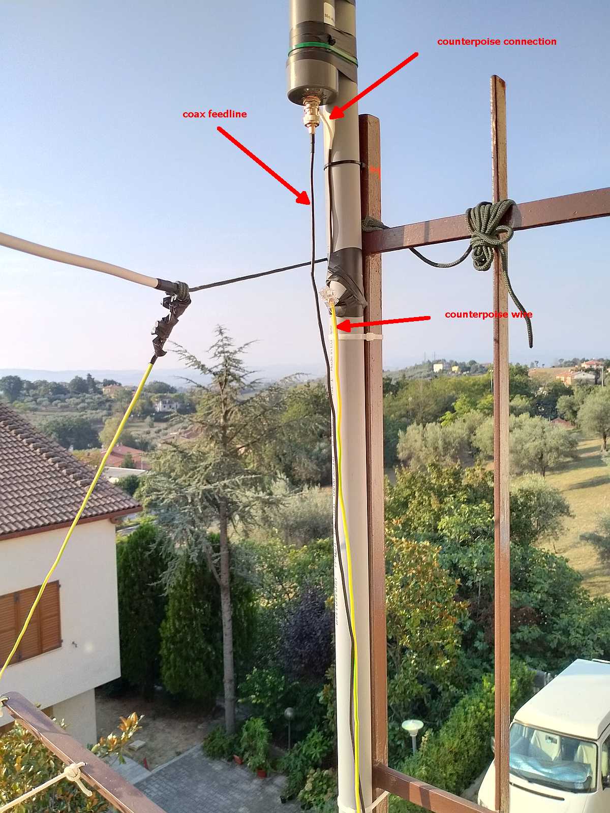
Let me detail the installation a bit better with this first image (click to enlarge):
As you can see in the above image, the whip is supported by a piece of PVC pipe which keeps it above the metal fencing of the balcony (or a support pole if you’ll use it) and I also connected a short run of insulated wire to the ground of BNC plug at the bottom of the whip. This short run goes to a wire clamp which allows it to connect to the “counterpoise” (ground) wire.
In my case, since the balcony was at 2nd floor, I didn’t have a way to give to the antenna a real ground, so I decided to run a length of wire (AWG #11) down the pipe and then along my balcony fencing (10m total). An alternative, which will also work for roof installations, would be using chicken wire (fencing). In such a case, you may lay as much chicken wire as you can on the floor/roof and connect the wire coming down from the whip ground to it. I haven’t that that (yet!) but I think it may further lower the noise and improve performances.
Notice that in the case of the Utwente Mini Whip, the antenna support pole is connected to metallic roofing so it has plenty of (virtual) ground.
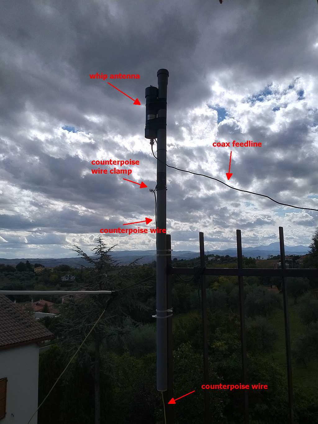
Later on, I improved the setup by raising the antenna a bit more and routing the wire (almost) horizontally from the feedpoint to reduce coupling with the vertical “counterpoise” wire.
The image below shows the final setup:
While not visible in the above image, I also wrapped the coax wire in a loop at the point where it’s held by the fencing and added some snap-on chokes to the coax at the point where it enters the building.
With all the modifications in place, the antenna started performing as it was designed to. The noise floor is still a bit higher than the one of the LLD, but given that it’s an active antenna, that’s to be expected
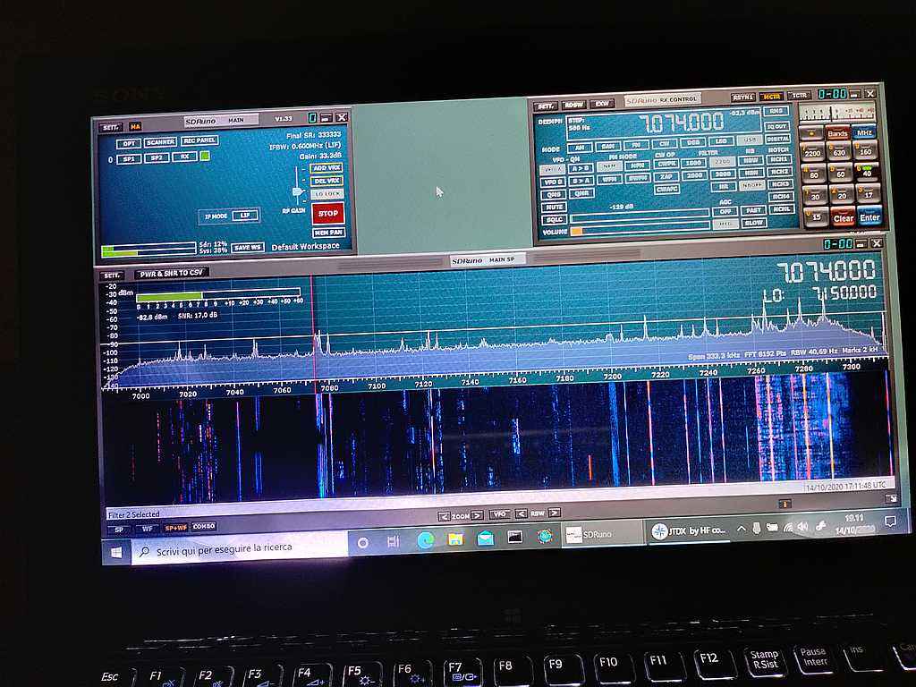
To give you an idea of the signals and noise floor, here are a couple of images taken from the screen of my laptop while running SDRuno. The first one shows the waterfall for the 40m band
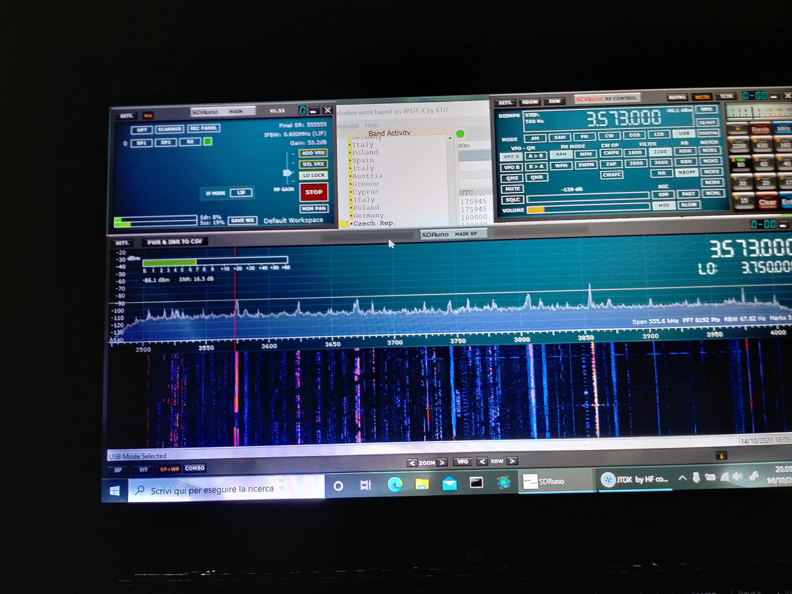
While the second one, below, shows the one for the 80m band:
At any rate, my usual way of testing antenna performance (and modifications effects), aside from some band scanning/listening, is to run an FT8 session for some hours (and optionally repeat it over some days) and then check the received spots.
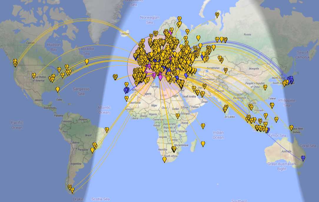
In the case of the Mini Whip, after all the modification to the setup, I ran an FT8 session using JTDX for some hours and the images below show the received spots. The first image shows the whole map of the received stations:
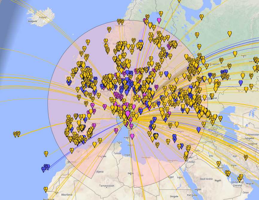
While the second one below is a zoom into the European region to show the various spots picked up there; the different colors indicate the 20m (yellow), 40m (blue/violet) and 80m (violet) bands:
As you can see, the Mini Whip performed quite well despite the “not exactly good” propagation.
While some time ago I’d have discarded the Mini Whip as a “noise magnet”, as of today, with a proper installation, I think it’s a keeper. While it can’t be compared to bigger antennas, I believe it may be a viable antenna for space-constrained situations. The only thing it needs is a bit of care when setting it up to allow it to work as it has been designed to.
Brilliant job, Grayhat! Thank you so much for sharing your experience setting up the Mini Whip antenna. As you stated, so many SWLs dismiss the Mini Whip as “noisy”–but with a proper ground, it seems to perform rather well. The benchmark example of a Mini Whip’s performance must be the U Twente Web SDR.
In my previous post, I mentioned how much I enjoy the built-in digital audio recorder in the new Icom IC-705. While I wouldn’t buy a QRP transceiver specifically for built-in audio recording–there are less expensive options out there–it is an incredibly useful feature in my world.
Their house is like so many others in that it is inundated with RFI (radio frequency interference). I find that the NCPL antenna does a fine job mitigating most of that noise on the mediumwave band when I position it so that the bulk of the interference is nulled.
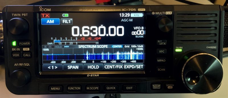
Monday morning, I tuned the IC-705 to my favorite local AM station: WAIZ on 630 kHz.
Weekday mornings, Dave and his “Wacky Wake-Up Crew” always put me in the right mood. They’re incredibly goofy/corny and 100% original.
It’s extraordinarily rare these days to find a local radio station, with local talent, creating a local daily radio show. Almost all of their ads are local, too.
I made the following off-air recording for myself, but decided to upload it for others to enjoy. I’m not sure what the receiver audio EQ or bandwidth filter was set to when I recorded this. It’s not a demo of receiver performance, just a little radio fun.
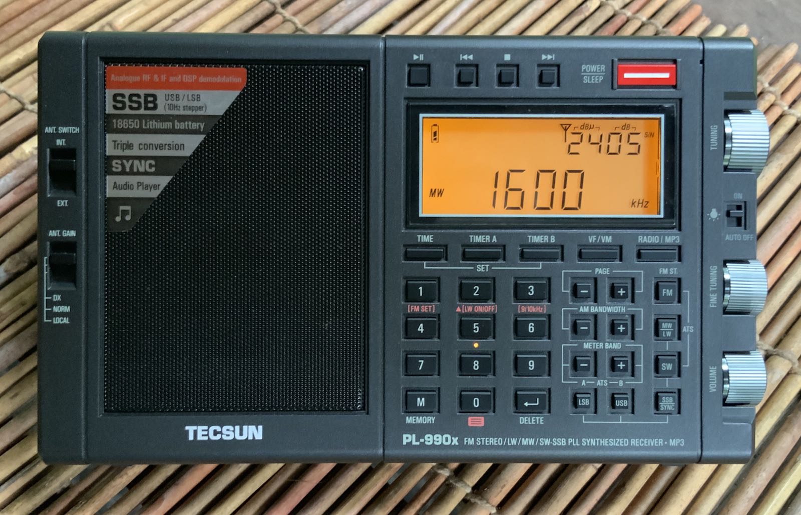
Many thanks to Anna at Anon-Co who recently shared an interesting “hidden feature” of the Tecsun PL-990 which allows the user to toggle between the internal ferrite antenna and telescoping whip antenna while on either the mediumwave or logwave bands.
Procedure:
1) Turn on the radio and then select either the MW or LW frequency band.
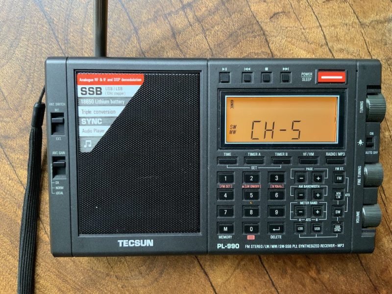
2) Press and hold the [ 3 ] key for about 2 seconds.
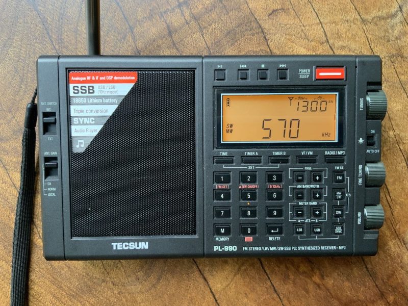
When the display shows “CH-5” (actually an “S” which stands for shortwave telescopic antenna) the radio is now set to MW/LW reception using the telescopic whip antenna.
The display will show MW (or LW) and SW on the left side of the screen.
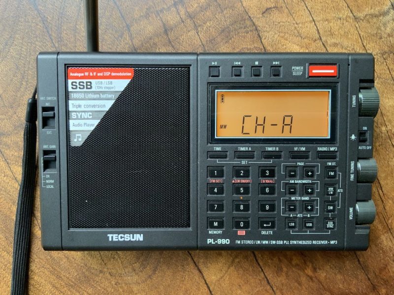
3) Press and hold the [ 3 ] key for about 2 seconds.
When the display shows “CH-A” (“A” stands for “AM”) the radio is now set to MW/LW reception using the internal ferrite antenna once again.
The display will also show only MW (or LW) on the left side of the screen.
Pressing and holding the [ 3] key essentially toggles between these two antenna settings.
I’ve actually found that, indoors, using the whip antenna on mediumwave has been more effective at mitigating RFI with strong local stations. The ferrite bar antenna has more gain, of course, but for locals it’s not necessarily needed.
Many thanks to SWLing Post contributor, Kostas (SV3ORA), for sharing the following guest post which originally appeared on his radio website:
How to build an automatic rig/antenna switching system
by Kostas (SV3ORA)
When I started collecting vintage rigs, I ended up in a line of rigs on my bench, that were sitting there, disconnected from any mains cables or the antenna. I wanted these rigs to be ready to fire at any time I wanted to, without having to connect/disconnect cables all the time. I also wanted to be able to compare different rigs performances at the flip of a switch, which is the only way this can be done on the HF quick fading conditions. For power cables, the solution was to leave them connected in the mains plugs all the time. My rigs that have an internal PSU, have mechanical switches, so they are isolated from the mains when they are switched off. The rigs that are powered by an external PSU, depend on the external PSU main switch for isolation (in case they haven’t mechanical switches on them), which in my case is mechanical and switches off the mains power, when the PSU is switched off.
However, for the RF cables, this was a different story. Having only one antenna and multiple rigs, means that you have to connect each rig to the antenna every time you want to operate each rig. This is not only boring and time consuming (you have to reach the back of the transceivers to connect/disconnect the connectors), but eventually causes the connectors of the coaxial cable and the rigs to wear out. I decided to make things better and make an RF rig selector for my rigs. This RF rig selector has been described in this link.
The current antenna I use is fine for transmitting, but in the noisy neighbourhood where I live, it picks up a lot of noise. I have tried many solutions, without significant effect in the noise level. This is why I decided to use a separate antenna for receiving, from that used for transmitting. This antenna will be some kind of loop probably, so as to be immune to noise or insensitive to the direction of the noise. It will be placed in a different location than the transmitting antenna, a location which will be less noisy. Unfortunately, the space I have for the TX antenna lies in a very noisy location in my property. So a separate RX antenna, in another physical location is a must. This means that a separate coaxial for the RX antenna must be used. Thankfully, the RX coaxial can be very small in diameter, passing easily through the sides of the windows, without extra holes.
To satisfy all of my requirements, I developed the circuit shown above. The circuit is able to switch a common antenna to four different rigs. Why four? Because this was the capacity of my switch and the number of connectors I had available. If you have a greater capacity switch and more connectors, expand the circuit to your needs.
The circuit of the shack switch, allows for 4 separate rigs to be selected, and two antennas, one for RX and one for TX. TX/RX antenna selection is being done automatically (split antenna operation) and controlled by the PTT of any of the rigs connected. This feature can be bypassed by the switch, so that the TX antenna can be used for both RX and TX. The same switch allows also RX operation with passive RX antennas of active ones. When in the active RX antenna position, power is passed to the remote RX preamplifier through the RX coaxial cable, using a bias-T circuit. The values of the bias-T circuit have been chosen very large, so as active RX antennas that operate at LF and lower could still be used. The RF relay defaults in the TX antenna, so that if there is a power failure, or if the circuit is not supplied with power, you can still receive (and transmit) with the TX antenna. The other way around, would be fatal for both the transceiver and the RX antenna (If you transmitted accidentally into it).
The PTT circuits are based on my transceivers. Unfortunately, there is no “standard” for the PTT circuits, each rig has its own way, so the PTT circuits must be thought for each of them. I followed an “inhibit” approach for the PTTs. That is, all the PTT switches are connected in series and DC is passed through them. If any of the rigs transmits, the PTT switch is opened and the circuit switches to the TX antenna. For the rigs that do not have an internal relay but output DC on TX instead, an additional small relay is used (for greater isolation and lossless switching). The only drawback of this “inhibit” topology is that the PTTs of all the rigs must be connected to the circuit simultaneously. If you want to exclude a rig of course, you may short circuit it’s PTT connector in the circuit. The PTT circuits as I said, are non-standard, so you might want to change the circuit to your needs, but anyway you got the idea.
Notice the connections in the circuit. One section of the RF switch (on the left) is used for the positive wire (central conductor of the coaxial) and another for the negative (braid of the coaxial). Why is that? This is because I canted to add a special feature to the switch. That is, the ability to disconnect the antenna from any rig when the rigs are not used. Previously, I used to disconnect the antenna coaxial from the transceiver when I was away, so as to protect the transceiver from antenna static discharges and possibly destroy it’s front end circuits. Now, with a single flip of the switch, I am able to do so. Because I wanted the switch to operate on different types of antennas (balanced or not) I decided to short circuit both poles of the antenna at this position, to equalize their charges.
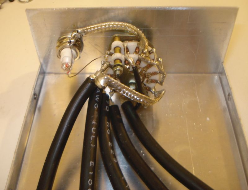
But equalizing their charges was not enough. I had to find a way to let these charges go to the ground, so that the antenna is discharged. Directly grounding the short circuit, did not seem a good thing to do, because the whole TX wire antenna on the roof would be grounded. Whether this is a good idea to avoid lightings or not, I do not know. So I decided to keep the short circuited antenna floating and instantly discharge it only when adequate static charge is built upon it. For this purpose, I used a neon tube, permanently connected to the switch NC (not-connected) position. When the switch is in the non-connected position, the tube lights up and discharges the antenna (both poles) if an appropriate amount of static charges has been built upon it. When the switch is in any of the selected rigs connections, the tube is disconnected, preventing it from lighting up when you transmit into the antenna. Note that this configuration, requires that the output (antennas) coaxial connectors must be isolated from the metal chassis of the RF switch!
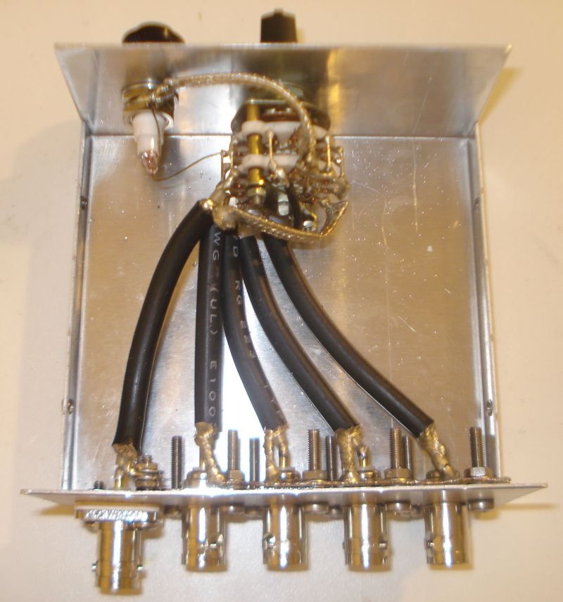
Isolation of the output antenna connectors has been done with a PVC sheet and isolated screw rings. Also note the usage of BNC connectors on TX and SMA on RX. I used BNC connectors for various reasons. They are excellent connectors with quick lock/unlock features. You do not need to screw them (and wear them out) and once fit in place they are not unscrewed. Once fitted in place, they allow for rotating the connection without unscrewing the cable or bending it. They can handle 100W easily. Despite all these features, they are much smaller in size and lighter. Their reduced size fits easily to reduced diameter cables like the RG-58 and similar. In an RF switch where there are lots of cables connected, this does make a difference. They are also very common and very cheap. There are even types that do not require soldering at all to fit a coaxial to them. I use BNC connectors even at my antenna side, as they have been proven to be quite waterproof. The types of BNC connectors I choose are not silver plated. Despite silver plated connectors are better, in the long term they are corroded by humidity and become much worst than the nickel plated connectors. The connectors I used are nickel plated with gold plated central conductors. I have found these types to be much more durable over the years, despite being cheaper. The same goes for the RX SMA connector, but I used an SMA connector there so as to accommodate thinner coaxial cables for RX.
The BNC connectors used, are the square flange types. I used this type of connectors because when they are fitted onto the chassis, they cannot be unscrewed, unlike the single-hole types. For the RX though, I used an SMA connector because it is even smaller and it can accommodate smaller diameter cables. The coaxial cable used for the internal switch connections on TX, is the RG-223. This cable is silver-plated (both the central conductor and the braid), it has double braid for increased shielding, it is of the same diameter as the RG-58 and it has a bit lower loss. The cable loss is negligible though for such small pieces of cable. The same type of cable has been used for the internal switch-relay connections as well as for the connections of the selector to the rigs. Appropriate lengths of RG-223 cables were cut and fitted with BNC connectors at one side and the appropriate rig connectors at their other side. For the RX antenna, you may use the thinner diameter cable you can find. I used a small piece of very thin coaxial (taken out of the WiFi card of an old laptop) and passed this piece through the side of the windows of the shack and through the mosquito net of the windows. No extra holes are required that way! For the rest of the RX cable, you can use whatever cable diameter you want, but I tried to use the smallest diameter I could find, so that the cable is as much phantom as possible.
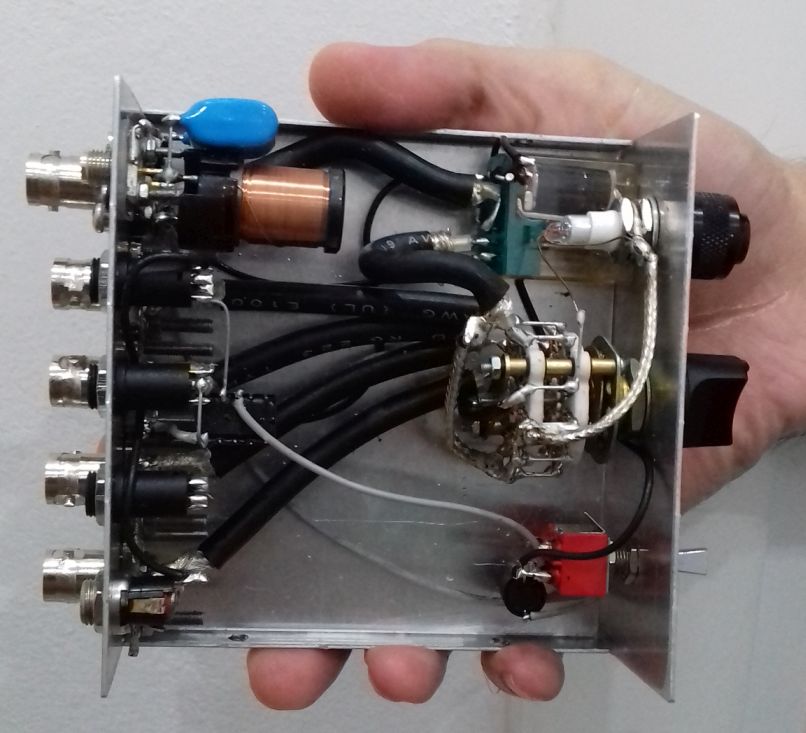
All the coaxial rig cables are grounded at the connectors side. I used a piece of coaxial braid and fitted it to the connectors screws. Then I soldered the braids of the coaxial cables onto this piece. Notice the black ring screw isolators at the antenna connector, to isolate it from the chassis. Speaking about the chassis, do not use a plastic chassis for the RF switch, use only a metal one! The picture below, as well as all the next pictures, show the RF cables arrangement, but note that the circuit in these pictures is not complete yet.
The coaxial cables are soldered onto the switch contacts. Where a ground connection is required, a piece of braid accomplishes this. Do not use thin wires, the device has to allow for at least 100W of HF RF power to pass through it. I have tested the switch with 200W of power and there were no problems at all. The neon tube directly connects to the appropriate switch contact and to the chassis.
The most important part of an RF switch is of course the switch itself. For 100W of HF RF power, I would suggest you to use a porcelain switch. I had a 5-positions 4-sections small porcelain switch, which I used. I connected two sections at each side in parallel (adjacent pins connected together). That is, two sections in parallel for the positive wire and two sections in parallel for the braid. I did that for various reasons. First, by using two contacts for each connection instead of one, you increase the power handling capability of the switch. Then, you ensure a sure-contact throughout the years. Any corrosion or wearing on the switch contacts would cause contact problems eventually. By using two contacts for each connection instead of one, you double the probability for a good contact. After all, I had a switch with more sections, so why not make a good use of them?
The completed selector is shown above. The relay was been taken out of an old CB radio. Use the best quality relay you can afford, as this will be switched quite often and it must handle at least 100W of RF power.
The results from the RF switch operation are quite satisfying. The overall construction is kept small and low profile. The switch makes a good contact despite being small. The automatic discharger seems to work well. On receive, there is some RF leakage, as I expected, in the near by cables, which is noticed in the higher HF bands or in very strong signals. The very sensitive receivers we use, are able to detect that. This RF leakage occurs even when the switch is in the NC position, where the antenna is disconnected and floating. So, to be honest I have not figured out if the leakage is from the switch or from the external cables in the shack. On TX, there is of course severe leakage from the transmitting coaxial to the rest of the ports. This IS expected. There is leakage even without using any selector at all, in the nearby receivers, when a transmitter operates at such high powers. There is nothing you can do about it really, unless your receiver has a mute capability, which I did not bother to take care of.
The TX/RX switching is taken care automatically and this is very useful and relaxing for the operator as he does not have to worry about anything. The active or passive RX antenna selector and the feature to disable the auxiliary RX antenna are really useful and you can do many antenna and rigs comparisons on-the-fly with it, by the flip of a switch. Depended on the noise level and the sensitivity you want to achieve, the switch will provide you the most optimal RX conditions instantly!
The most important thing though, is that the goal of this project was achieved. I am able to switch the antenna to whatever rig I want at the flip of a switch. And before I go away, at the flip of a switch I can isolate and automatically discharge the antenna when needed. This is so much more convenient than having to connect and disconnect cables all the time. I can also now use a separate antenna for RX, which greatly improves reception in my case. This antenna is automatically switched by any rig I have and I do not have to worry about anything. I can also do comparisons between different antennas on RX, which is crucial in deciding which antenna is better for receiving. All these features make this little simple to build circuit, so useful and an integral part of the shack.
Thank you for sharing this practical and affordable project with us, Kostas!

 Many thanks to SWLing Post contributor, Steve Allen (KZ4TN), who shares the following guest post: