Many thanks to SWLing Post contributor, Paolo Viappiani, who shares the following guest post:
ETON Elite Satellit: an expensive flop
by Paolo Viappiani, Italy
Introduction
After various and sometimes conflicting announcements that have created strong expectations in radio listening enthusiasts, ETON has recently launched on the extra-European market (basically in the United States) what should have been its “top of the range” portable, the Elite Satellit model . Aesthetically (and also functionally) inspired by the previous E1 model, the new portable radio should have been free from the defects of its predecessor, in particular as regards the “sticky” coating of the plastic case but also with respect to other technical drawbacks repeatedly reported by users (display contrast and shading, etc.).
The new Elite Satellit was announced to look practically identical to the E1 model and to use the same cabinet, but with various additions and improvements: RDS, FM-HD reception, Air Band, etc. A frequency resolution of 10 Hz in the shortwave bands, a PBT (Pass-Band Tuning) facility, a large LCD display with the possibility of changing its background color were also provided.
It is therefore obvious that its release was highly anticipated, and the resulting expectation gave rise to numerous pre-orders of the radio in the United States, where the main distributor was (and still is) the well-known Universal Radio company owned by Fred Osterman [1].
Unfortunately, the initial boom in sales of the ETON Elite Satellit was followed by many return requests due to the poor performances of the radio and the numerous defects encountered by users, also reported in a lot of videos and negative reviews on the Internet [2].
Fred Osterman himself, disappointed by the performance of a radio that he should have sold as an excellent portable, began to test the individual devices in his own laboratory and to return to ETON all the units that did not meet the declared specs (basically the vast majority of those received for sale) [3]. All this caused great confusion at ETON, which was forced to somehow remedy its errors (mainly due both to a very approximate alignment of the circuits and to an almost non-existent final quality control).
Unfortunately, despite the precautions adopted “hastily” by ETON, most of the “overhauled” devices that were returned to Universal Radio continued not to comply with the specifications, so that Fred Osterman, who is a good technician and a very honest dealer, decided to cancel most of the orders received and to sell the very few radios found to be in good working order within the United States only, (see again note [3]). I myself placed an order from Universal Radio for an ETON Elite Satellit on August 8, 2022 (Order ID: #8992932, retail price $599.99 plus shipping and import customs duties), but Fred was forced to “drastically cut” the orders received and to cancel mine too, due to the impossibility of satisfying the many customers on this side of the pond. However, my desire to have an example of the ETON Elite Satellit in my hands, in order to be able to see, test and judge the new radio it was really great, and great was also the wish to realize if the many negative impressions circulating on the web were or were not justified and true.
So I decided to look for other ways to buy the “latest cry” of ETON. The opportunity presented itself to me, almost unexpectedly, by visiting the American site of Amazon [4].
The purchase and the arrival of the radio; my first impressions
I therefore ordered an ETON Elite Satellit portable radio on the Amazon.com website on January 17, 2023 at the price of $698.16 (including shipping and customs duties). I report in Figure 1 the screenshot concerning my order #113-3575479-2262609 which, as it appears, was delivered to me on January 23, 2023, after only five days; this demonstrates the truthfulness of my statements.
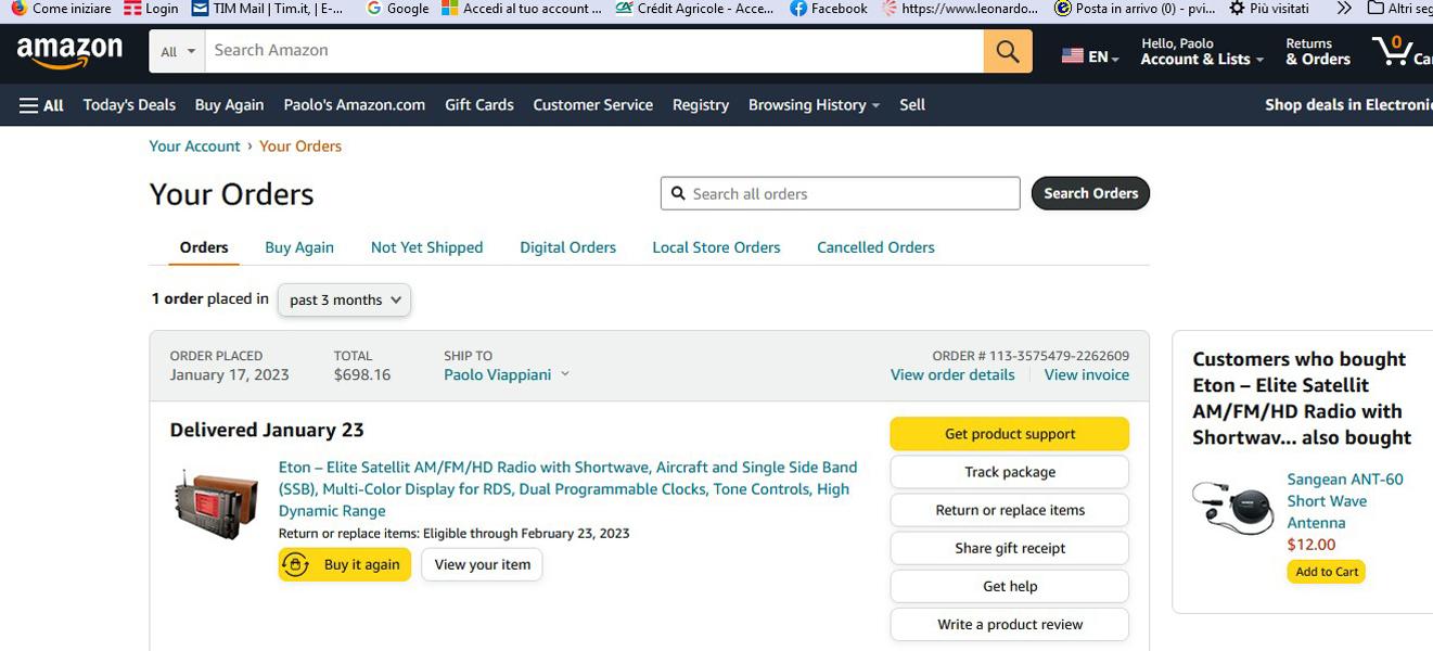
Figure 1: A Screenshot of my Amazon.com order dated January 17, 2023.
The shipment was delivered to me by UPS courier in the usual Amazon packaging in a plastic bag (Figure 2).
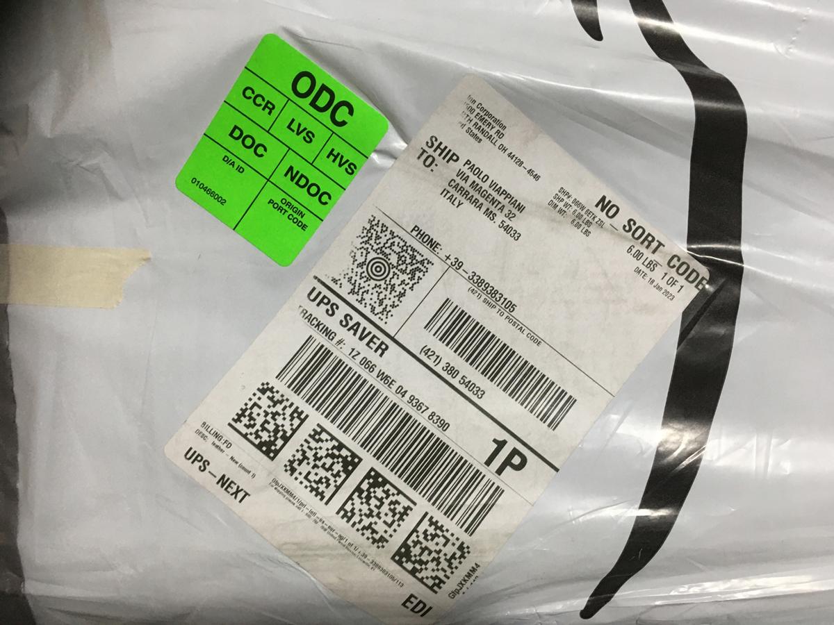
Figure 2: The UPS label and the Amazon plastic bag.
Inside the envelope was a cardboard box containing the radio, in understandably less than perfect conditions (Figure 3).
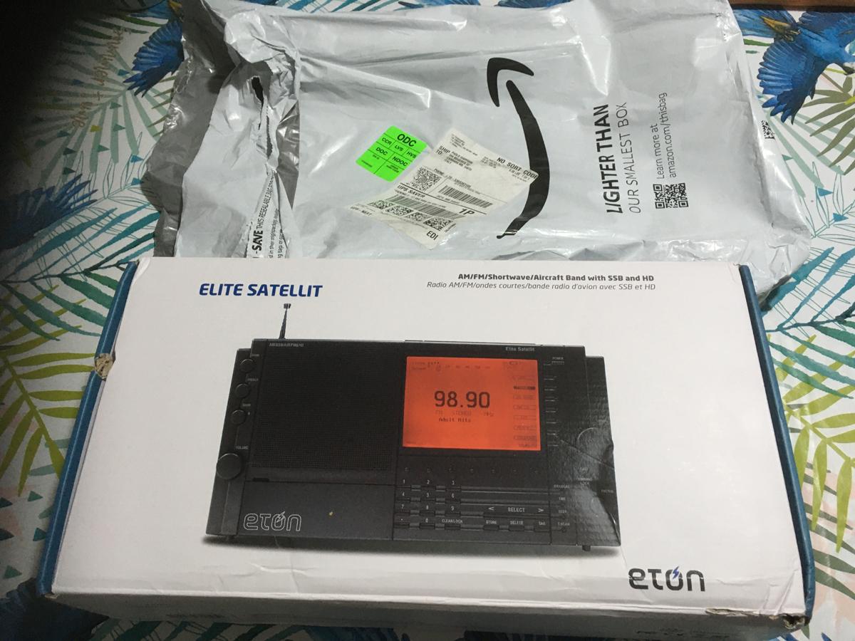
Figure 3: The cardboard box of the ETON Elite Satellit.
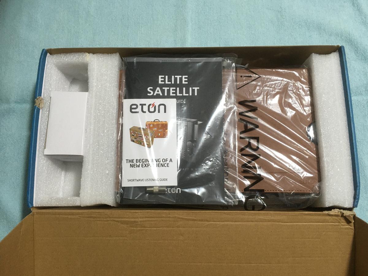
Figure 4: The contents of the radio box.
Once the package was opened, the contents of the box looked like in Figure 4: two shock-absorbing spacers held the device in position (inserted in a plastic bag) and its AC power supply (into a white box, and obviously with a 117V input voltage). There was also the “User Guide” in a paper version and a “mini-guide” to listening to short waves; completely absent was the CD that used to be enclosed in the box of the previous E1 version of the radio.
Continuing with the operations, I came across a sort of brown plastic cover intended for the protection of three sides of the radio (front, top and back) which can be held in position by some magnets and is provided with two circular holes in correspondence with the tuning knobs and volume of the radio (Figure 5).
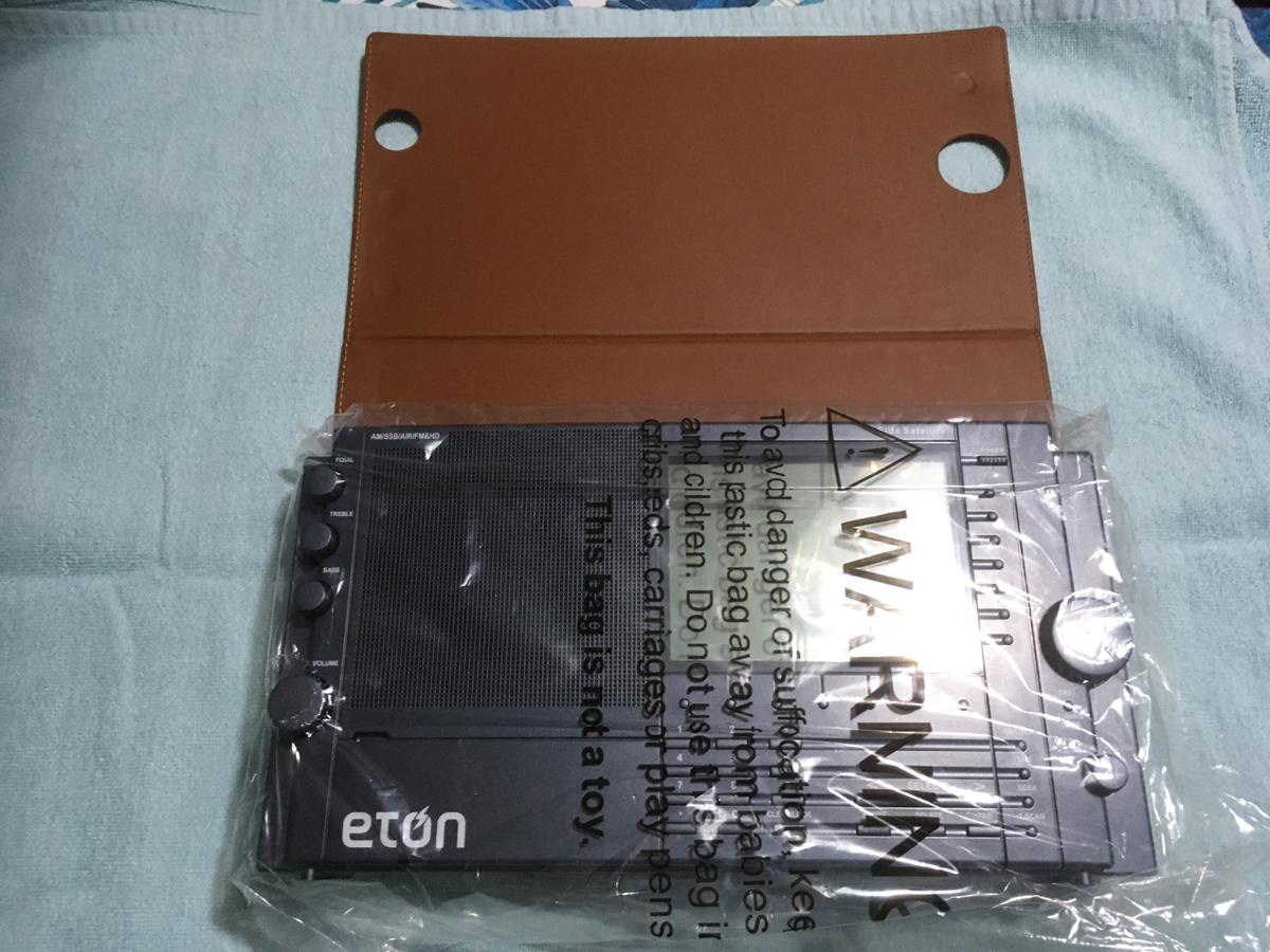
Figure 5: The ETON Elite Satellit radio and its “case” (?)
I omit to make comments on this “protection”; I only say that in my opinion it is useless (and ugly too) and I believe that the gentlemen of ETON could have wasted their energies otherwise; but maybe someone likes it too…
Figures 6 and 7 show the front and back of the portable radio as soon as it has been removed from the protective plastic bag. Note the almost identical appearance of the cases of the Elite Satellit and of the previous E1 model.
Continue reading →