 Many thanks to SWLing Post contributor and RX antenna guru, Grayhat, for another excellent guest post focusing on compact, low-profile urban antennas:
A linear loaded dipole for the SWL
by Grayhat
What follows is the description of an antenna which may allow to obtain good performances even in limited space, the antenna which I’m about to describe is a “linearl loaded dipole”(LLD) which some call the “cobra” antenna due to the “snaking” of its wires
The arms of the antenna are built using 3-conductors wire (which may be flat or round) and the 3 conductors are connected this way:

That is, connected “in series”, this means that, the electrical length of the antenna will be three times its physical one; this does NOT mean that the antenna will perform like a single wire of the same (total) length, yet it allows to “virtually” make it longer, which in turn gives it good performance even with relatively short sizes. Plus, the distributed inductance/capacitance between the wires not only gives it a number of “sub” resonance points, but also helps keeping the noise down (in my experience below the noise you’d expect from a regular dipole). At the same time it offers better performances than what one may expect from a “coil loaded” dipole. Plus, building it is easy and cheap and the antenna will fit into even (relatively) limited spaces (a balcony, a small yard and so on…).
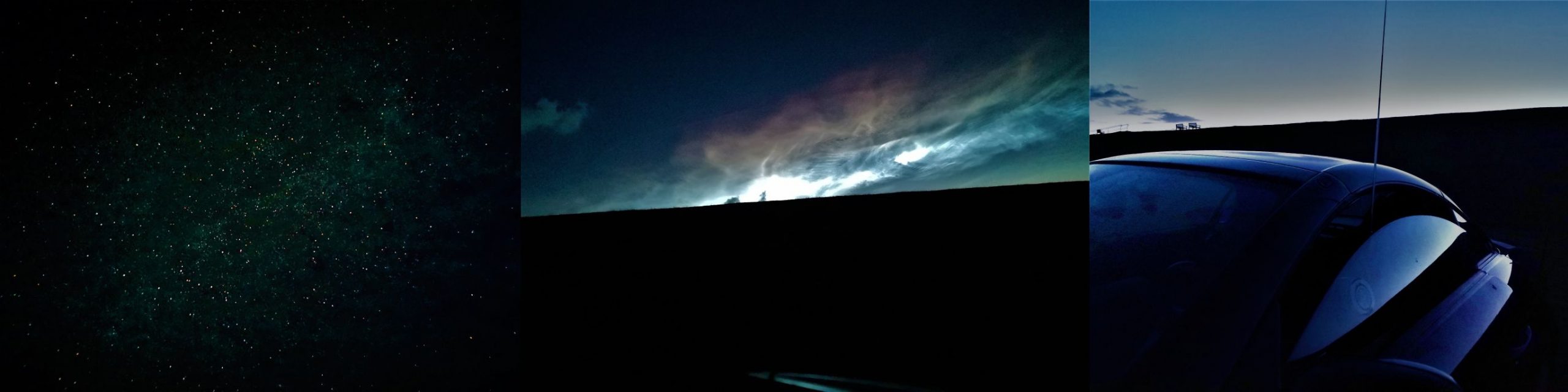
Interested–? If so, read on and let me start by showing my (short – 9mt total) LLD installed on a balcony:
Here it is in all its “glory”–well, not exactly–I fiddled with it lately since I’m considering some mods so the tape isn’t correctly stuck and it has been raised and lowered quite some times, but in any case that’s it.
Bill of Materials
Here’s what you’ll need to build it (the links are just indicative, you may pick different stuff or buy it locally or elsewhere).
- Some length of 3-conductors electrical wire which will fit your available space (pick it a bit longer to stay on the safe side), it may be flat or round, in my case I used the round type since it was easily available and cheap: https://amzn.to/3g2eZX3
- A NooElec V2 9:1 BalUn–or, if you prefer you may try winding your own and trying other ratios. I tested some homebuilt 1:1, 1:4 and 1:6 and found that the tiny and cheap NooElec was the best fitting one): https://amzn.to/3fNnvce
- A small weatherproof box to host the BalUn: https://amzn.to/33vjZy3
- A center support which may be bought or built. In the latter case, a piece of PCV pipe with some holes to hold the wires should suffice. In my case I picked this one (can’t find it on amazon.com outside of Italy): https://www.amazon.it/gp/product/B07NKCYT5Z
- A pair of SMA to BNC adapters: https://amzn.to/37krHwj
- A run of RG-58 coax with BNC connectors: https://amzn.to/2JckHcR
Plus some additional bits and pieces like some rope to hang the antenna, some nylon cable ties, a bit of insulated wire, duct tape and some tools. Notice that the above list can be shortened if you already have some of the needed stuff and this, in turn will lower (the already low) cost of the antenna.
Putting the pieces together
Ok, let’s move on to the build phase. The first thing to do will be measuring your available space to find out how much wire we’ll be able to put on the air; in doing so, consider that (as in my case), the antenna could be mounted in “inverted Vee” configuration which will allow to fit the antenna even in limited space.
In any case, after measuring the available space, let’s subtract at least 1m (50cm at each end) to avoid placing the antenna ends too near to the supports. Also, if in “inverted Vee” config, we’ll need to subtract another 50cm to keep the feedpoint (center/box) away from the central support.
Once we’ve measured, we may start by cutting two equal lengths of 3-conductor wire. Next, we’ll remove a bit of the external sleeve to expose the three conductors and then we’ll remove the insulator from the ends of the three exposed wire (and repeat this at the other end of the cable and for both arms).
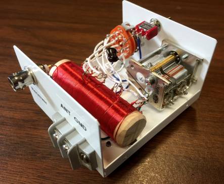
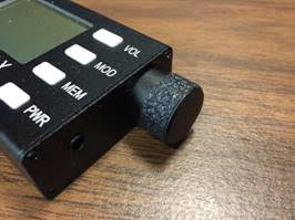
The resulting ends of each arm should look somewhat like in the example image below

Now we’ll need to connect the wires in series. We’ll pick one of the cables which will be the two arms of our antenna and, assuming we have the same colors as in the above image, we’ll connect the green and white together at one end and the black and green together at the other end. Repeat the same operation for the second arm and the cables will be ready.
Now, to have a reference, let’s assume that the ends of each arm with the black “free” (not connected) wire will go to the center of our dipole.
Leave the two arms alone for a moment, and let’s install the balun inside the waterproof box. To do so, we’ll start by cutting a (small) hole through the single rubber cap found at one side of the box, then insert the cap reversed, so that it will protrude to the inside of the box and not to the outside. Slide the balun SMA connector through the hole so that it will protrude outside the box.
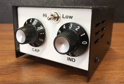
Now use a marker to mark the balun position and remove the balun from the box. Pick a piece of wood/plastic or other insulating material, cut it to size (refer to marking and to balun size) and drill four holes matching the one found on the balun board. Slide four screws through the holes and lock them with nuts, the screws should be long enough to extrude for some mm. Now insert the balun in the screws using the holes present on the balun board and lock it with nuts (be gentle to avoid damaging the balun). At this point, add some “superglue” to the bottom of the support we just built, slide the balun SMA connector through the rubber cap hole we already practiced, and glue the support to the bottom of the waterproof box. Wait for the glue to dry.
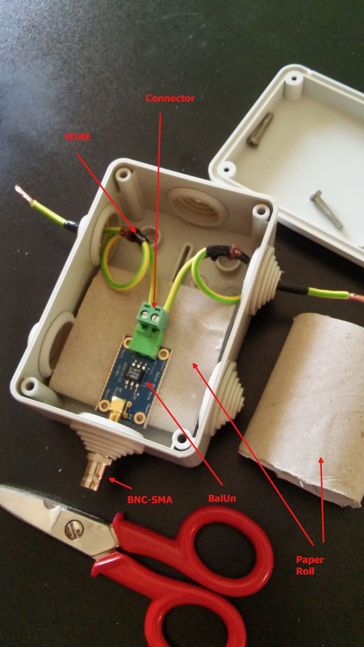
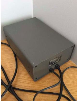
Just to give you a better idea, see the photo above. That’s a photo of the early assembly of my balun. Later on, I rebuilt it as described above (but took no pics!), the image should help you understanding how it’s seated inside the box–by the way in our case it will be locked by the screws to the plastic support we glued to the box.
While waiting for the glue to dry, we may work on the dipole centerpiece.
If you bought one like I did, connecting the arm “black” (see above) wires should be pretty straightforward. If instead you choose to use a PVC pipe you’ll have to drill some holes to pass and lock the wire so that the strain will be supported by the pipe and not by the wire going to the balun box. In either case, connect a pair of short runs of insulated wire to the end (black) wire coming from each end. Those wires should be long enough to reach the balun wire terminal block inside the box.
Assuming the glue dried, it’s time to complete the feedpoint connection.
Bring the two wires coming from the centerpoint inside the waterproof box. Pick one of the wire terminal blocks which came with the balun (the “L” shaped one should be a good choice) and connect the wires to it. Then, slide the block in place until it locks firmly. After doing so, close the box and screw the SMA-BNC adapter onto the SMA connector coming from the balun. Our centerpiece and arms will now be ready, and will be time to put our antenna up!
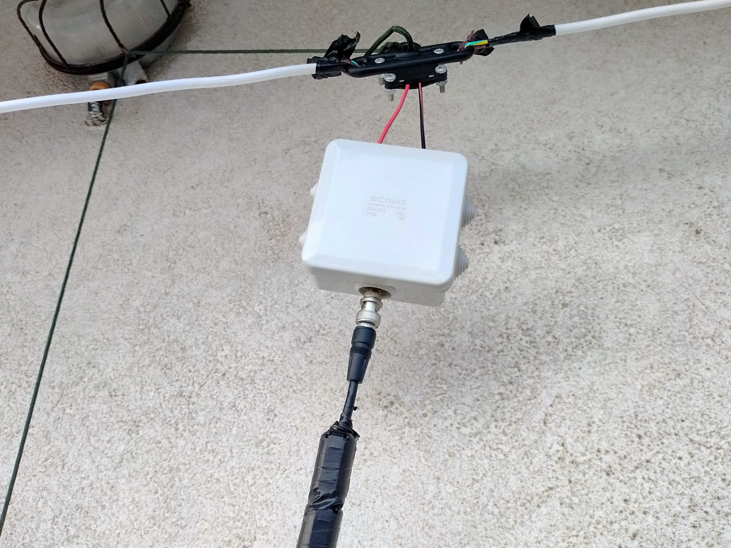

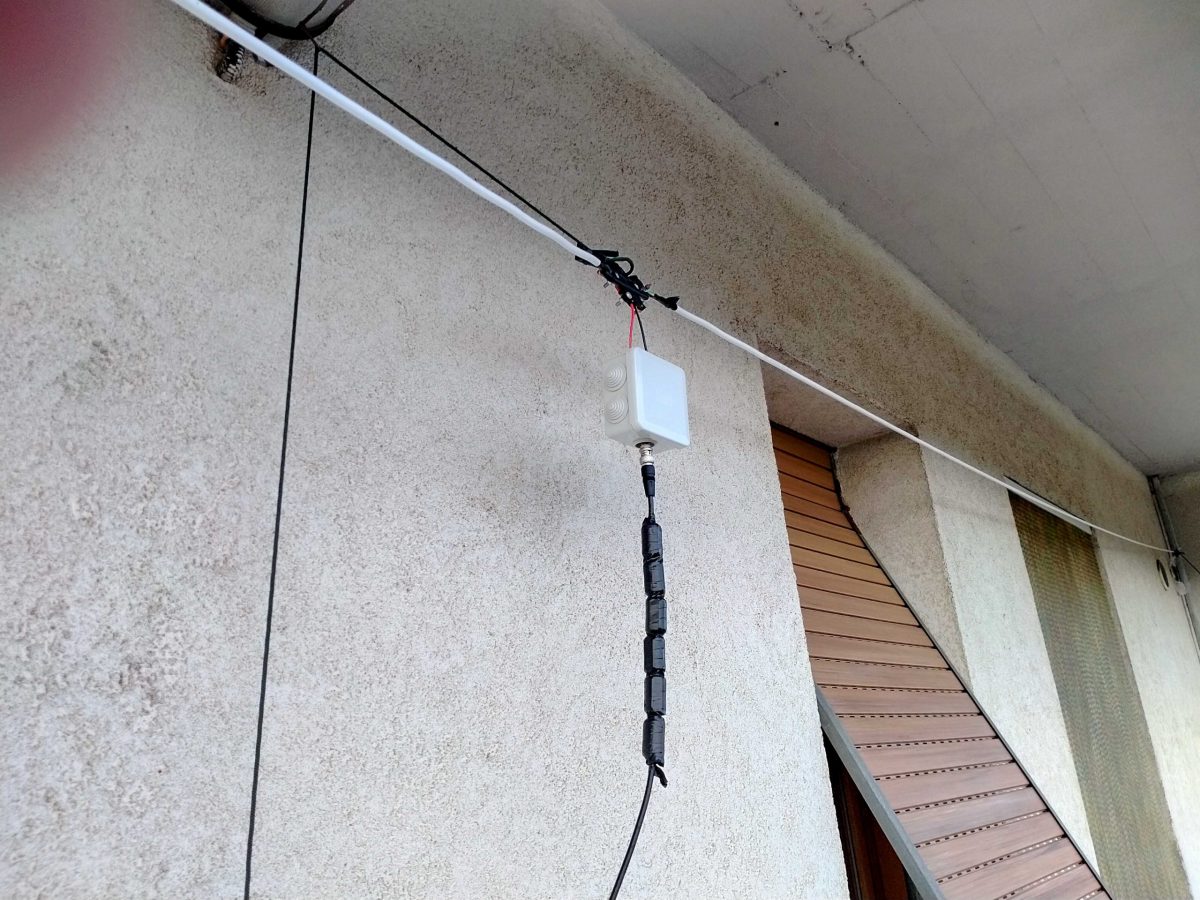
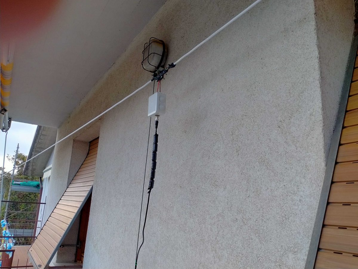
I’ll skip the instructions about holding the arm ends and the centerpiece up, since I believe it should be pretty straightforward. Just ensure to put the antenna as high as possible and, if you have room make the arms as long as possible. In my case, due to my (self-imposed) limitations, the antenna was installed on a balcony. The arms have a length of about 3.5m each and the feedpoint (in the image above) sits at about 9m off the ground.
The more acute readers probably noticed those “blobs” on the coax, they are snap-on ferrite chokes I added to the coax (there are more of them at the rx end) to help tame common mode noise. I omitted them from the “BoM” since they may be added later on.
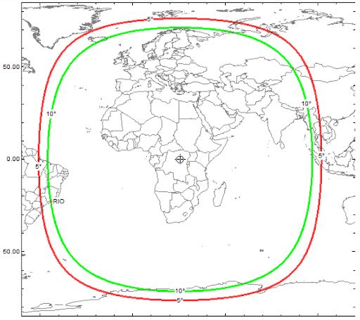
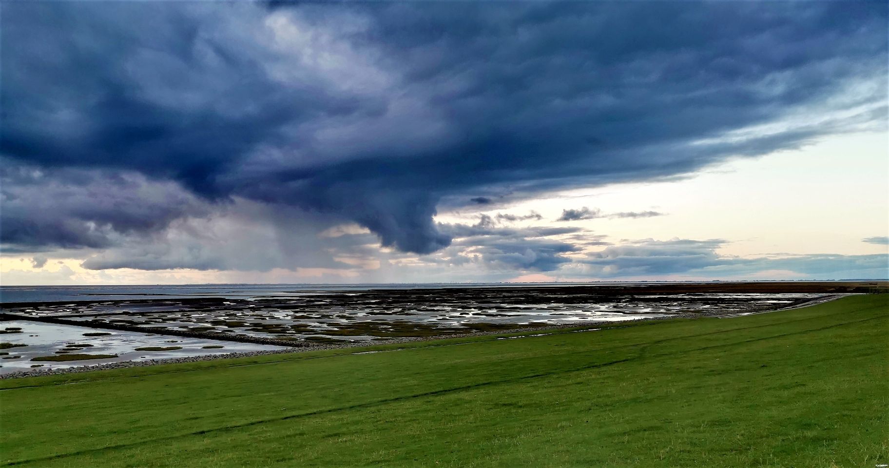
Anyhow, now that you have your LLD up it will be time to give it a test! In my case, I decided to start by running an FT8 session to see what the antenna could pick up during 8 hours, and the result, on the 20 meters band, is shown on the following map (click to enlarge):
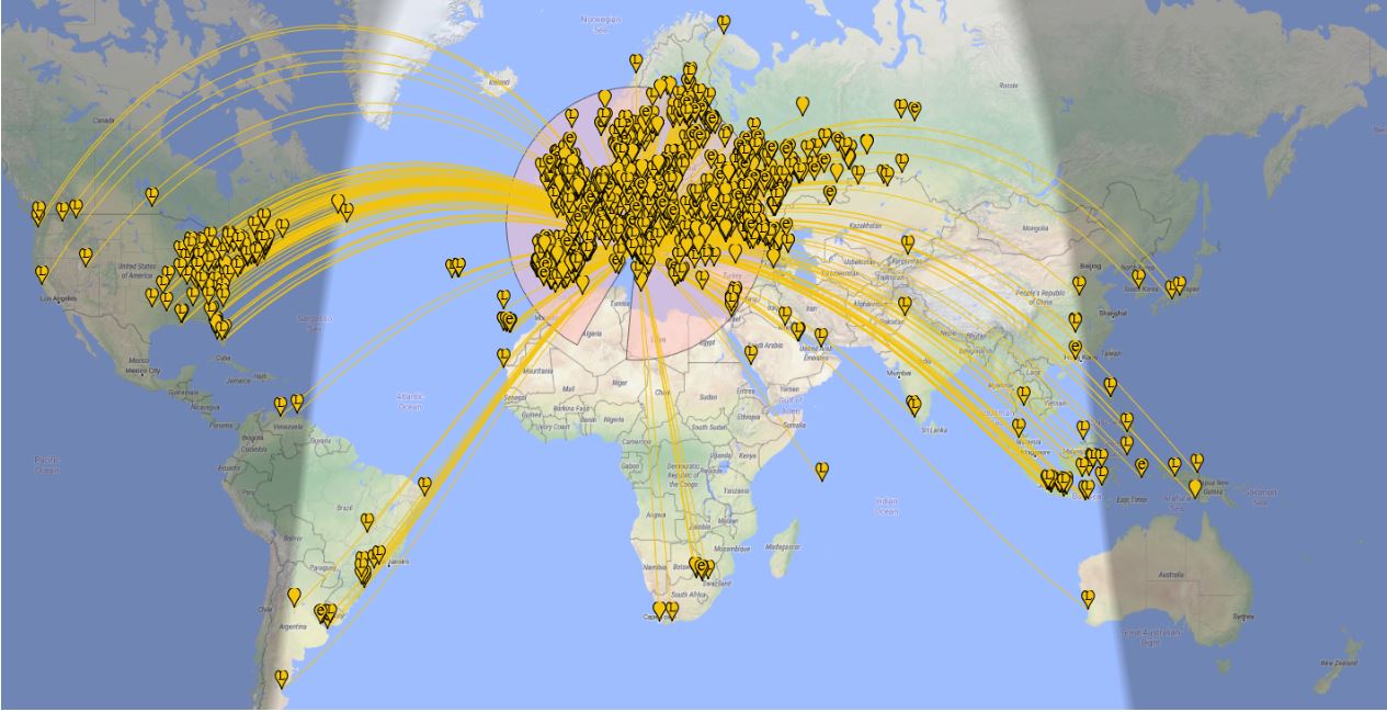
Later, that same antenna allowed me to pick up signals from the Neumayer station in Antarctica–not bad, I think!
Some final notes
While running my “balcony experiment”, I built and tested several antennas, including a vanilla “randomwire”, a dipole, and a T2FD.
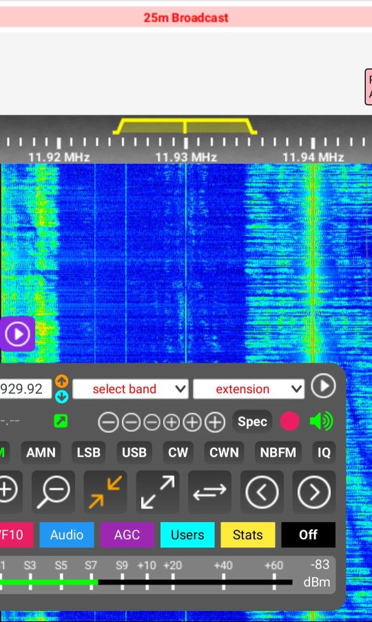
Compared to those, the LLD offers much less noise and better reception on a wide frequency range. By the way, it won’t perform miracles, but it’s serving me well on the LW band, on most ham bands, and even up to the Aircraft bands–indeed, was able to pick up several conversations between aircraft and ground air traffic control.
All I can suggest is that given a linear-loaded dipole is so simple, quite cheap, and may fit many locations, why don’t you give it a spin–? 🙂