Category Archives: Guest Posts

Loop-On-Ground Antenna Part 2: Tom upgrades his low profile, low noise, portable DXing antenna

Many thanks to SWLing Post contributor, TomL, who shares the following guest post:


Loop on Ground Part 2

by TomL
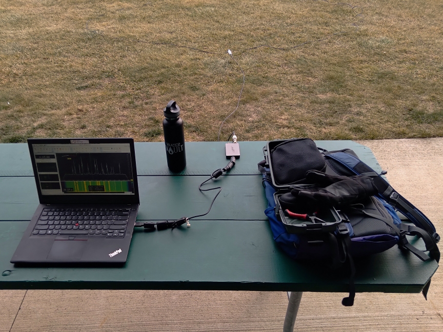
My previous Loop on Ground (LoG) experiment was useful which entailed connecting my Wellbrook loop amplifier to a 100 foot loop of speaker wire in the field at my favorite local Forest Preserve. It really brought in stations I had never heard before or strong stations in a more powerful way that made the audio really pleasant to listen to.  This report will describe more experiments with smaller wire loops to see what the limitations are.  100 feet of wire is quite a lot of wire to mess around with especially in the cold weather or public places that do not have as much private space.

I don’t understand all the electrical interrelationships but a long posting at RadioReference.com had  a great discussion about creating a 160-20 meters LoG receive-only antenna. It is 11 pages long but is worth reading how “nanZor” experimented with various parameters for general use. Kudos to him for documenting the findings as the design changed over time. You can find it here:

https://forums.radioreference.com/threads/160-20m-log-loop-on-ground.370110/

nanZor basically boils it down to a few guidelines.

  1. Keep it on the ground. Lifting the wire more than an inch or two decreased the lower angle signal reception greatly.
  2. Calculate the optimal length for one full wavelength of wire at the highest target frequency, say for example, the top of the 20 meter band (14350 kHz). 936/14.350 MHz * 0.9 velocity factor of simple insulated wire = 58.7 feet.  You can round up to 60 feet, no big deal since this is broadband.  The antenna should have a predictable reception pattern from 1/10th wavelength up to 1 full wavelength. Outside that range, the pattern gets “squirrely”.
  3. Using a 9:1 balun seemed to be a little better than a 4:1 balun at the antenna feedpoint. This gets into things I cannot measure and has to do with rising impedance as a loop gets closer to ground level. I am not sure but I think my Wellbrook amp has a built in 4:1 balun and it seems to work just fine.
  4. Make sure to use an RF Choke at BOTH sides of the feedline coax cable. He was adamant that the loop can get easily unbalanced and allow noise into the antenna and/or feedline and so it must be isolated and the ground allowed to “float” in his words.

Personally, I also wanted to use less wire and happened to have a length of 42 feet of landscape wire which should work well below 5 MHz with the Wellbrook amp engaged.  Results were not bad even though on hard frozen ground. Signal levels were down a little compared to the 100 foot of wire.  Here are a couple of examples, first one in a fast food parking lot with a grass field next to it and second at the usual Forest Preserve parking lot on a grass field.  I made sure that my car blocked the view of the wire so people would not get nervous!

La Voz Missionaria, Brazil:

Voice of Welt from Issoudun France in Kurdish:

These are not necessarily “DX” but definitely good for SWLing. I like the signal strength with the amplifier inline at the antenna feedpoint and I did not have to use an RF Choke at the receiver side as was suggested.

I had a 75 foot long insulated wire and used that at the Forest Preserve parking lot on a couple of different days.  Lower frequency signal strength and signal/noise ratio improved a little bit to be noticeable.

US Air Force HFGCS “numbers” station. Remote controlled from Andrews or Grand Forks bases (https://en.wikipedia.org/wiki/High_Frequency_Global_Communications_System), there was no way for me to know which of the 6 transmitters it was coming from:

BBC from Tinang Philippines in Korean:

Then, as nanZor suggested in his postings, I purchased a 9:1 balun/RF choke (it has both a balun and an RF choke built-in) from Ham Radio Outlet and put that in place of the Wellbrook amplifier.
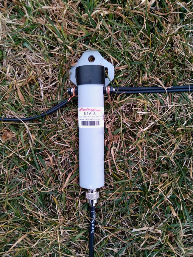
I have not worked with it, but it is reported that the Nooelec.com v2 model is cheaper and works just as well – https://swling.com/blog/2019/10/the-nooelec-balun-19-v2/

Examples below with the 42 foot loop and 9:1 balun/choke, no amplifier:

KSDA, Agat Guam in English

WB8U doing a POTA activation of Leavenworth State Fishing Lake

VOLMET weather, Shannon Ireland

HCJB Quito Ecuador, probably in Quechua

As a side note, there is a posting that mentions low-angle DX is better with regions that have better “ground conductivity”, salt water being the best. I have no way of verifying this.  See post# 126 by KK5JY Matt.

So, bottom line is that a Loop on Ground can be useful for pleasant SWLing and portable.  Best to use it on grass, not asphalt.  The loop amplifier is useful to get signal levels up if you have to use a smaller loop size but the signal/noise ratio will suffer due to its smaller aperture.  And, warning, the public will find a way to trip over the wire no matter where you set it up (I may try putting the wire around my car if I can park on a grass surface and/or use the gaudiest, brightest neon green or orange wire I can find – they can’t trip over THAT, can they?).

TomL


Thanks, Tom, for sharing your update. Obviously, the LoG is working brilliantly. It’s amazing that you got such clear reception from the parking lot of a fast food restaurant.  If you were using a vertical instead, I bet signals would have been buried in the noise. 

I can also relate to people tripping over antenna wires. I remember one POTA activation recently (the first activation in this three park run) where I intentionally laid my counterpoise on the ground, off a foot path, in the brush and where I couldn’t imagine anyone ever stepping. Ten minutes into the activation and for no reason, someone walked off the path, into the brush, and it snagged them. Maybe I’m just a Ninja level trapper and never realized it!?

Thanks again for sharing the results of your LoG, Tom. Inspiring! 
Tom builds a portable Loop-On-Ground antenna

Many thanks to SWLing Post contributor, TomL, who shares the following guest post:


My First Loop-On-Ground antenna

A number of people have mentioned the Loop On Ground (LOG) antenna in the past as a good receive-only antenna.  I did some research but could only find a few examples by amateur radio operators.

Matt Roberts (KK5JY) has a good article including some antenna theory and measurements, you can find it here:

http://www.kk5jy.net/LoG/ 

Someone named Tom (KG3V) has a write up on it but it is a little short on details:

https://kg3v.com/2020/01/04/loop-on-ground-the-simplest-receive-antenna-you-will-ever-build-and-it-works/

Stana Horzepa (WA1LOU) has something similar:

https://tapr.org/loop-on-ground-log-antenna/

I also read somewhere that for transmitting, a LOG antenna is useless as it radiates much of the energy right into the ground!  But I didn’t care about that.  I needed something for receive I can deploy easily without supports and take down just as easily.  As you may recall, my home condo is literally saturated with noise and I cannot null it out.  So a wire looped on the ground is supposed to work?  You bet it does!

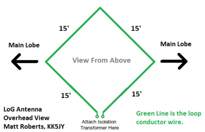
Of course, there are some conditions to meet.  There has to be enough flat ground away from people or pets (or lawn mowers!) who would get tangled in the wire on the ground.  The wire should be as close to the ground as possible (although I had good results laying the wire on top of cut grass).  The loop of wire can vary in circumference from about 20 feet to 150 feet (the shorter length will stay in an omnidirectional pattern higher in frequency but lower in signal pickup and vice-versa for the longer length).  The wire needs to be insulated.  That’s about it!

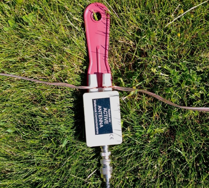
So, off to the hardware store to buy a cheap spool of 100 foot 18 gauge speaker wire.  But, the articles mention using a balun and they all made their own.  I did not feel like doing that (I am not that good at making things from scratch) and I did not want to spend money ordering one. More reading somewhere informed me that my existing Wellbrook Medium Aperture loop amplifier has a built-in balun at the antenna side of the device.  Hallelujah!

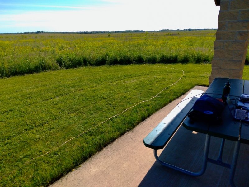
I bundled together the wire, Wellbrook parts and battery supply, small laptop and Airspy HF+ to my favorite Lake Nelson Forest Preserve.  The shelter there is little used and is adjacent to the prairie with cut grass.  It did take a good 15 minutes to lay out the 100 feet of wire on the ground while trying to keep it as flat as possible. And I did not have enough space for a circle, so I ended up with an oblong shape.  The long sides are facing directly north-south, so in theory (I think) this gives me an oblong shaped reception pattern east-west.  The photo shows half of the wire laying on the grass.

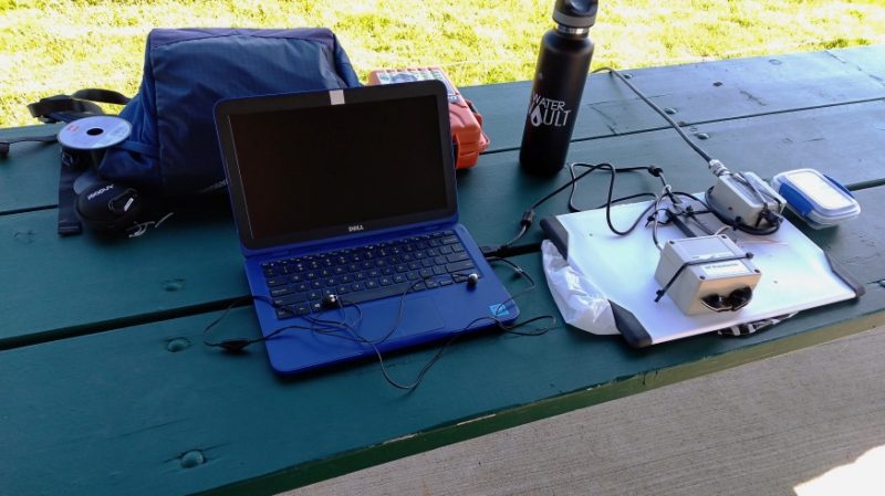
I ended up with this setup on a picnic table at the rear end of the shelter.  The coax wire goes from the Wellbrook amp into its power module, then to a Cross Country Wireless preselector, then to the Apirspy HF+ and laptop.

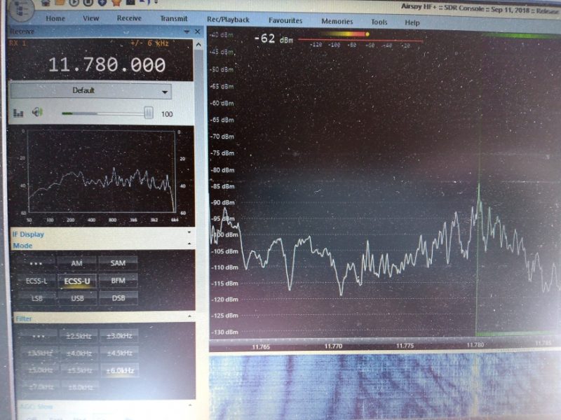
I was really impressed by the signal strength of the usual suspects like Radio Nacional da Amazonia.  I could see that the Wellbrook amp was boosting signals across the board with only a little extra noise.

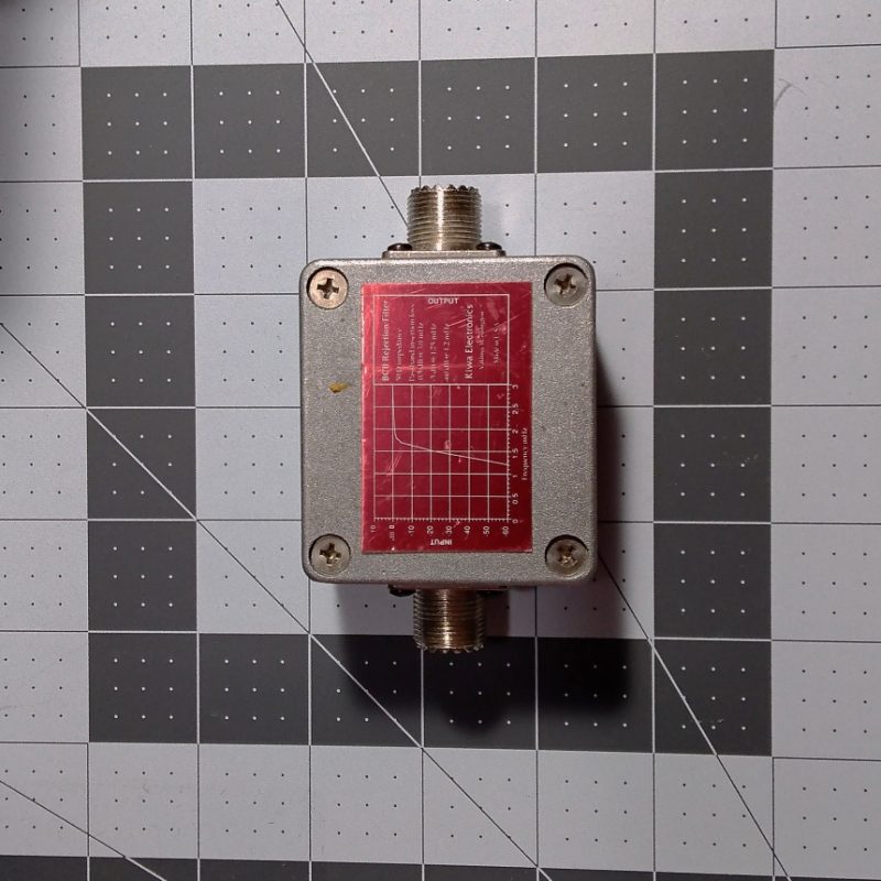
I use the preselector to try to keep the Airspy radio from overloading, especially mediumwave broadcast signals which can sound like a small amount of extra “hash” type noise in the background.  I have since added into the accessory chain an old Kiwa Electronics BCB filter that does a great job of knocking down the frequencies below 2 MHz.

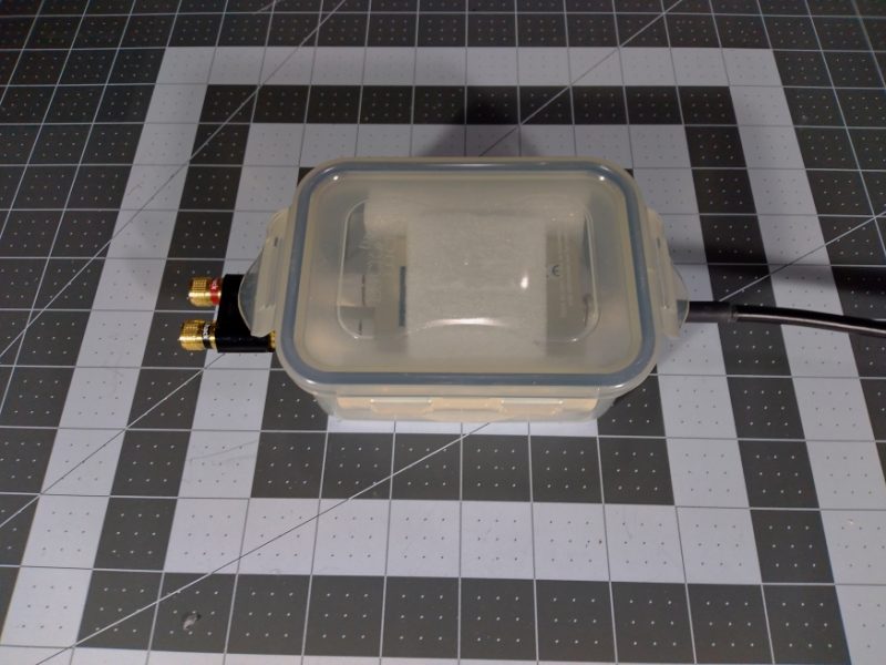
I have also since added a water resistant box to enclose the Wellbrook amp to keep it safe from getting stepped on or too wet.

Also, a couple of weeks later I was able to go to a campgound and try out 60 feet of wire but the result was noisier since I was surrounded by RV vehicles in a crowded campsite.  It was not horrible and I was able to listen to some good radio stations but location can matter with any antenna.

I hope you like the recordings below.  Because of some serious health issues this summer, these May 31 2020 recordings & report are just being published now (I am recovering slowly but surely!).  My small laptop is under-powered, so I was only able to record MP3 files one at a time.  It kept me busy as I went from one frequency to the next and kept recording anything I heard.  I was able to hear a couple of stations I never heard before and that is a success in my book.

It remains to be seen if this antenna is as good as my 19 foot vertical antenna attached to the top of the car roof, especially low-angle DX signals.  Maybe you will have the chance to experiment as well and share your experience, too.  Now, will a small loop-on-ground antenna around my car parked late at night at a far corner of the grocery store work OK???  I will have to try it!

Recordings (crank up the volume if it is too weak):

22:00 UTC, Radio Saudi (Arabic) 11915 kHz

22:04 UTC, KDSA Adventist Radio (Indonesian) 11955 kHz

22:14 UTC, KDSA Adventist Radio (English) 12040 kHz

22:20 UTC, Voice of Korea (Japanese) 11865 kHz

22:23 UTC, Yemen Radio (heavily jammed) 11860 kHz

22:35 UTC, Radio Brazil Central (Portuguese) 11815 kHz

22:50 UTC, WWV booming in 10000 kHz

23:11 UTC, UnKnown (might be FEBC) 9795 kHz

23:15 UTC, China Radio Int’l (Spanish teaching Chinese, from Kashi) 9800 kHz

23:17 UTC, China Radio Int’l Business Radio (from Xianyang) 9820 kHz

23:19 UTC, China Radio Int’l (Chinese from Urumqi) 9865 kHz

23:21 UTC, Voice of Korea (Korean) 9875 kHz

23:23 UTC, Maybe Radio Taiwan without jamming from CNR 9900 kHz

23:34 UTC, China Radio Int’l (Chinese from Bamako Mali) 7295 kHz

23:43 UTC, Radio Nacional da Amazonia 6180 kHz (& 11780 kHz around 40 seconds)

23:50 UTC, MAYBE China PBS from Xinjiang in Kazakh (nothing else listed on schedules) 6015 kHz

23:56 UTC, Radio Mali (French announcer humming to music and acting crazy) 5995 kHz

00:07 UTC, Radio Rebelde (Spanish w/clear signal, Bauta, Cuba) 5025 kHz

00:15 UTC, 75 meter Amateur Radio 3913 kHz (LSB)

00:27 UTC, CHU Ottawa 3330 kHz

00:30 UTC, XEPPM Radio Educacion (Spanish Mexico City) 6185 kHz


This is brilliant Tom! Thank you for sharing. 

Our antenna guru contributor, Grayhat, has been encouraging me (understatement!) to build a Loop-On-Ground antenna but I haven’t done this yet because, at home, our driveway would interfere with its deployment. That and I have no RFI to speak of in my rural/remote home so my skyloop antenna is tough to beat. But having one available for portable use would make a lot of sense.  I’m going to put this on my 2021 project list!

Post Readers: Do you use a LoG antenna at home or in the field? Please comment!

How to Build a Simple Linear-Loaded Dipole for Low-Noise Shortwave Radio Listening

Many thanks to SWLing Post contributor and RX antenna guru, Grayhat, for another excellent guest post focusing on compact, low-profile urban antennas:


A linear loaded dipole for the SWL

by Grayhat

What follows is the description of an antenna which may allow to obtain good performances even in limited space, the antenna which I’m about to describe is a “linearl loaded dipole”(LLD) which some call the “cobra” antenna due to the “snaking” of its wires
The arms of the antenna are built using 3-conductors wire (which may be flat or round) and the 3 conductors are connected this way:

That is, connected “in series”, this means that, the electrical length of the antenna will be three times its physical one; this does NOT mean that the antenna will perform like a single wire of the same (total) length, yet it allows to “virtually” make it longer, which in turn gives it good performance even with relatively short sizes. Plus, the distributed inductance/capacitance between the wires not only gives it a number of “sub” resonance points, but also helps keeping the noise down (in my experience below the noise you’d expect from a regular dipole).  At the same time it offers better performances than what one may expect from a “coil loaded” dipole. Plus, building it is easy and cheap and the antenna will fit into even (relatively) limited spaces (a balcony, a small yard and so on…).

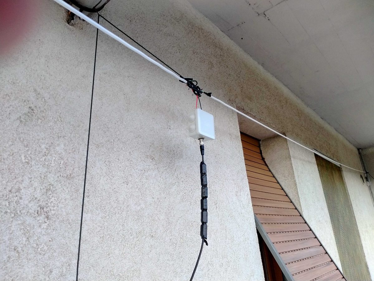
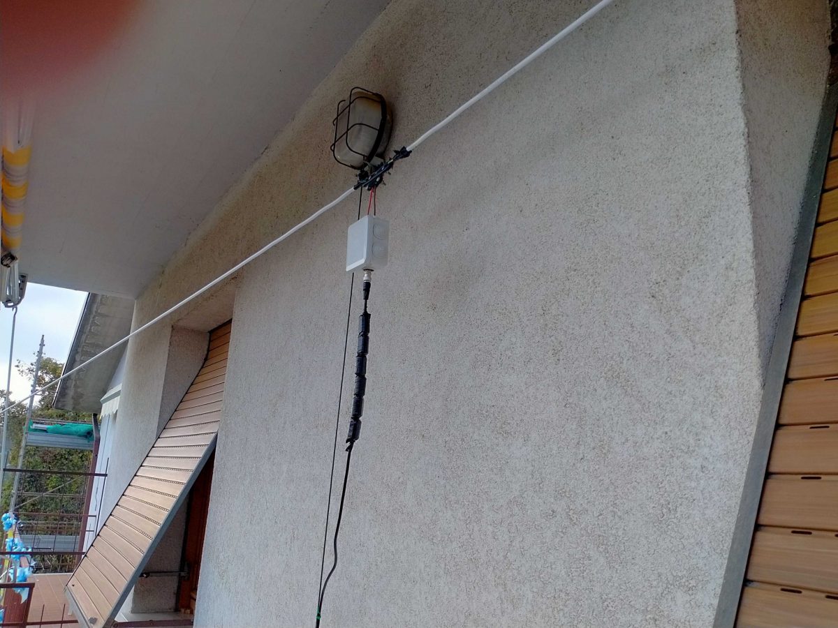
Interested–? If so, read on and let me start by showing my (short – 9mt total) LLD installed on a balcony:

Here it is in all its “glory”–well, not exactly–I fiddled with it lately since I’m considering some mods so the tape isn’t correctly stuck and it has been raised and lowered quite some times, but in any case that’s it.

Bill of Materials

Here’s what you’ll need to build it (the links are just indicative, you may pick different stuff or buy it locally or elsewhere).

  • Some length of 3-conductors electrical wire which will fit your available space (pick it a bit longer to stay on the safe side), it may be flat or round, in my case I used the round type since it was easily available and cheap: https://amzn.to/3g2eZX3
  • A NooElec V2 9:1 BalUn–or, if you prefer you may try winding your own and trying other ratios. I tested some homebuilt 1:1, 1:4 and 1:6 and found that the tiny and cheap NooElec was the best fitting one): https://amzn.to/3fNnvce
  • A small weatherproof box to host the BalUn: https://amzn.to/33vjZy3
  • A center support which may be bought or built. In the latter case, a piece of PCV pipe with some holes to hold the wires should suffice. In my case I picked this one (can’t find it on amazon.com outside of Italy): https://www.amazon.it/gp/product/B07NKCYT5Z
  • A pair of SMA to BNC adapters: https://amzn.to/37krHwj
  • A run of RG-58 coax with BNC connectors: https://amzn.to/2JckHcR

Plus some additional bits and pieces like some rope to hang the antenna, some nylon cable ties, a bit of insulated wire, duct tape and some tools. Notice that the above list can be shortened if you already have some of the needed stuff and this, in turn will lower (the already low) cost of the antenna.

Putting the pieces together

Ok, let’s move on to the build phase. The first thing to do will be measuring your available space to find out how much wire we’ll be able to put on the air; in doing so, consider that (as in my case), the antenna could be mounted in “inverted Vee” configuration which will allow to fit the antenna even in limited space.

In any case, after measuring the available space, let’s subtract at least 1m (50cm at each end) to avoid placing the antenna ends too near to the supports. Also, if in “inverted Vee” config, we’ll need to subtract another 50cm to keep the feedpoint (center/box) away from the central support.

Once we’ve measured, we may start by cutting two equal lengths of 3-conductor wire. Next, we’ll remove a bit of the external sleeve to expose the three conductors and then we’ll remove the insulator from the ends of the three exposed wire (and repeat this at the other end of the cable and for both arms).

The resulting ends of each arm should look somewhat like in the example image below

Now we’ll need to connect the wires in series. We’ll pick one of the cables which will be the two arms of our antenna and, assuming we have the same colors as in the above image, we’ll connect the green and white together at one end and the black and green together at the other end. Repeat the same operation for the second arm and the cables will be ready.

Now, to have a reference, let’s assume that the ends of each arm with the black “free” (not connected) wire will go to the center of our dipole.

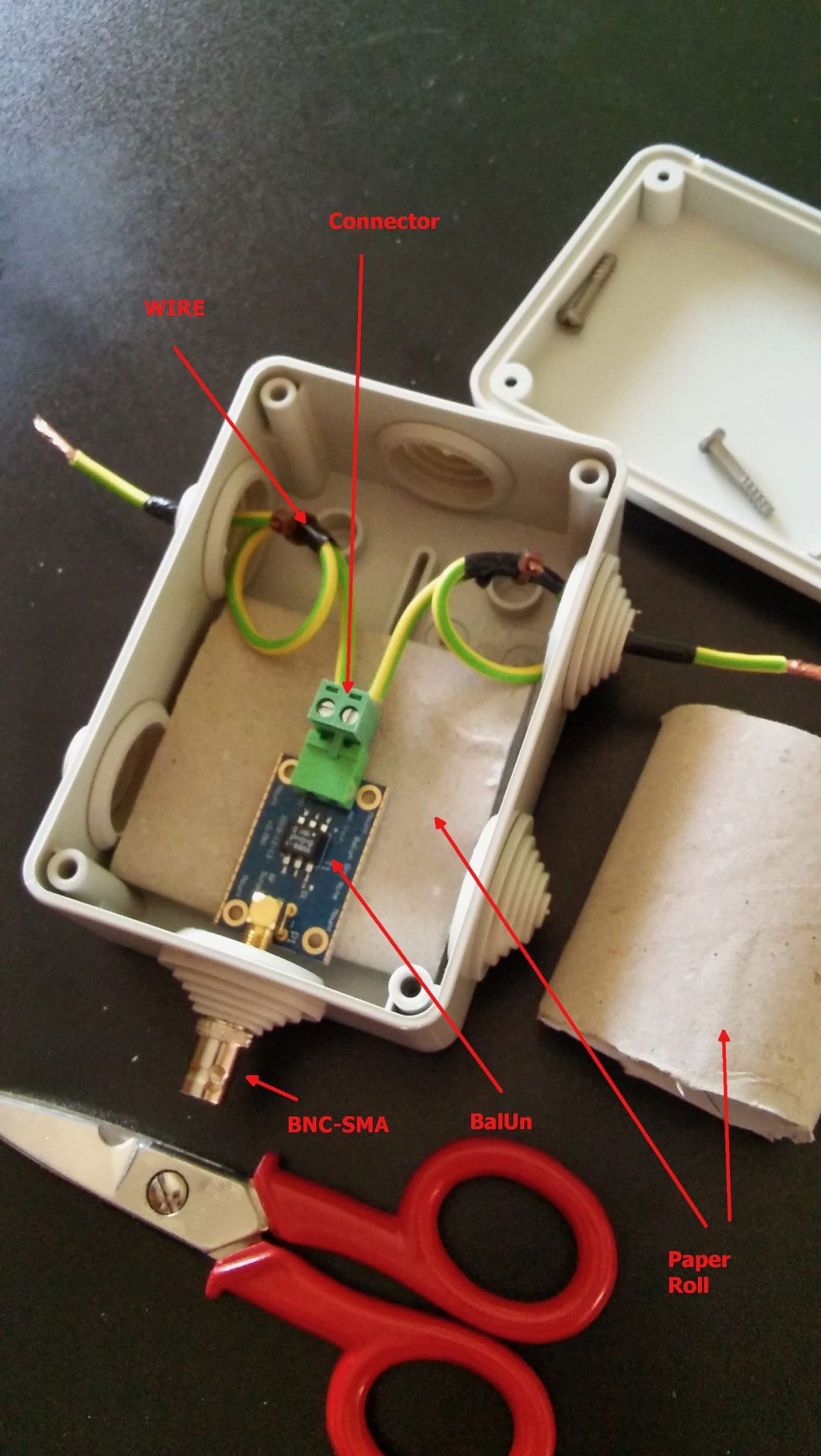
Leave the two arms alone for a moment, and let’s install the balun inside the waterproof box. To do so, we’ll start by cutting a (small) hole through the single rubber cap found at one side of the box, then insert the cap reversed, so that it will protrude to the inside of the box and not to the outside. Slide the balun SMA connector through the hole so that it will protrude outside the box.

Now use a marker to mark the balun position and remove the balun from the box. Pick a piece of wood/plastic or other insulating material, cut it to size (refer to marking and to balun size) and drill four holes matching the one found on the balun board. Slide four screws through the holes and lock them with nuts, the screws should be long enough to extrude for some mm. Now insert the balun in the screws using the holes present on the balun board and lock it with nuts (be gentle to avoid damaging the balun). At this point, add some “superglue” to the bottom of the support we just built, slide the balun SMA connector through the rubber cap hole we already practiced, and glue the support to the bottom of the waterproof box.  Wait for the glue to dry.

Just to give you a better idea, see the photo above. That’s a photo of the early assembly of my balun. Later on, I rebuilt it as described above (but took no pics!), the image should help you understanding how it’s seated inside the box–by the way in our case it will be locked by the screws to the plastic support we glued to the box.

While waiting for the glue to dry, we may work on the dipole centerpiece.

If you bought one like I did, connecting the arm “black” (see above) wires should be pretty straightforward. If instead you choose to use a PVC pipe you’ll have to drill some holes to pass and lock the wire so that the strain will be supported by the pipe and not by the wire going to the balun box. In either case, connect a pair of short runs of insulated wire to the end (black) wire coming from each end. Those wires should be long enough to reach the balun wire terminal block inside the box.

Assuming the glue dried, it’s time to complete the feedpoint connection.

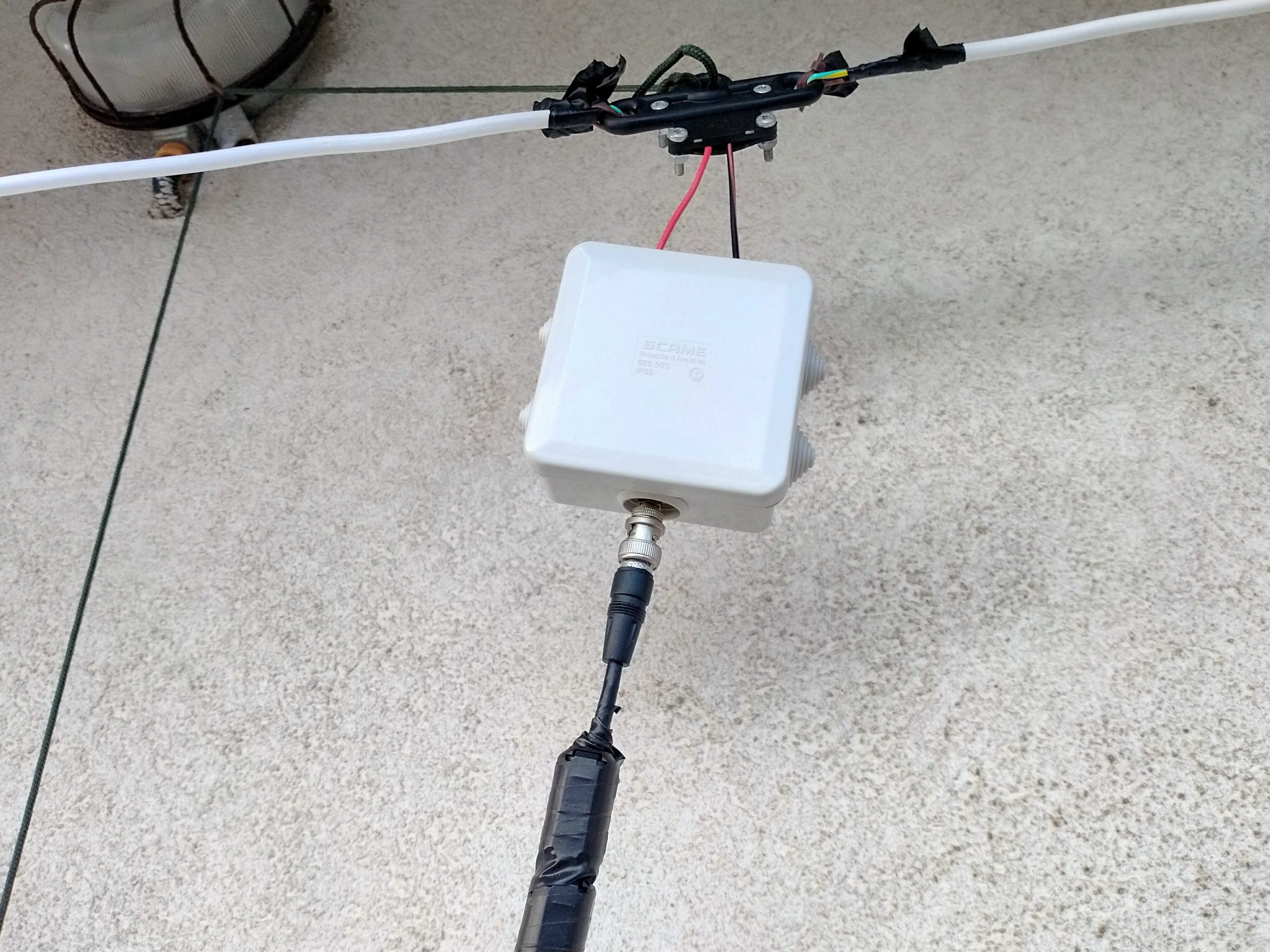
Bring the two wires coming from the centerpoint inside the waterproof box. Pick one of the wire terminal blocks which came with the balun (the “L” shaped one should be a good choice) and connect the wires to it. Then, slide the block in place until it locks firmly. After doing so, close the box and screw the SMA-BNC adapter onto the SMA connector coming from the balun. Our centerpiece and arms will now be ready, and will be time to put our antenna up!

I’ll skip the instructions about holding the arm ends and the centerpiece up, since I believe it should be pretty straightforward. Just ensure to put the antenna as high as possible and, if you have room make the arms as long as possible. In my case, due to my (self-imposed) limitations, the antenna was installed on a balcony. The arms have a length of about 3.5m each and the feedpoint (in the image above) sits at about 9m off the ground.

The more acute readers probably noticed those “blobs” on the coax, they are snap-on ferrite chokes I added to the coax (there are more of them at the rx end) to help tame common mode noise. I omitted them from the “BoM” since they may be added later on.

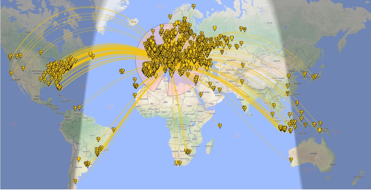
Anyhow, now that you have your LLD up it will be time to give it a test! In my case, I decided to start by running an FT8 session to see what the antenna could pick up during 8 hours, and the result, on the 20 meters band, is shown on the following map (click to enlarge):

Later, that same antenna allowed me to pick up signals from the Neumayer station in Antarctica–not bad, I think!

Some final notes

While running my “balcony experiment”, I built and tested several antennas, including a vanilla “randomwire”, a dipole, and a T2FD.

Compared to those, the LLD offers much less noise and better reception on a wide frequency range. By the way, it won’t perform miracles, but it’s serving me well on the LW band, on most ham bands, and even up to the Aircraft bands–indeed, was able to pick up several conversations between aircraft and ground air traffic control.

All I can suggest is that given a linear-loaded dipole is so simple, quite cheap, and may fit many locations, why don’t you give it a spin–?  🙂

Matt’s Monster Mediumwave Radio Selectivity Shootout!

Many thanks to SWLing Post contributor, Matt Blaze (WB2SRI), for sharing another brilliant audio comparison featuring benchmark portable radios:


Medium wave selectivity shootout

by Matt Blaze

I did another monster medium wave portable receiver comparison, this time with the aim of comparing receivers’ ability to deal with weak signals in the presence of strong adjacent channels.

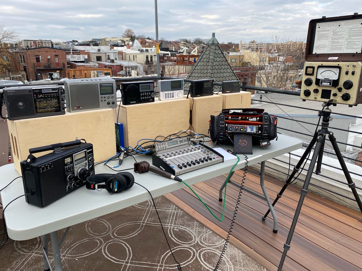
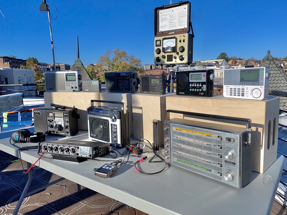
Once again, I went up to the roof with eight MW portables with built-in antennas and recorded them simultaneously along with my “reference signal”, from an Icom R-9500 with an active loop on the roof. As before, I recorded a narrated stereo mix with the Icom on the left and the rotation of radios for a minute or two each on the right, but have “solo” tracks available for the full time for each radio. The nine receivers in the lineup this time included:

  • Icom R-9500 (with amplified Wellbrook loop antenna on roof)
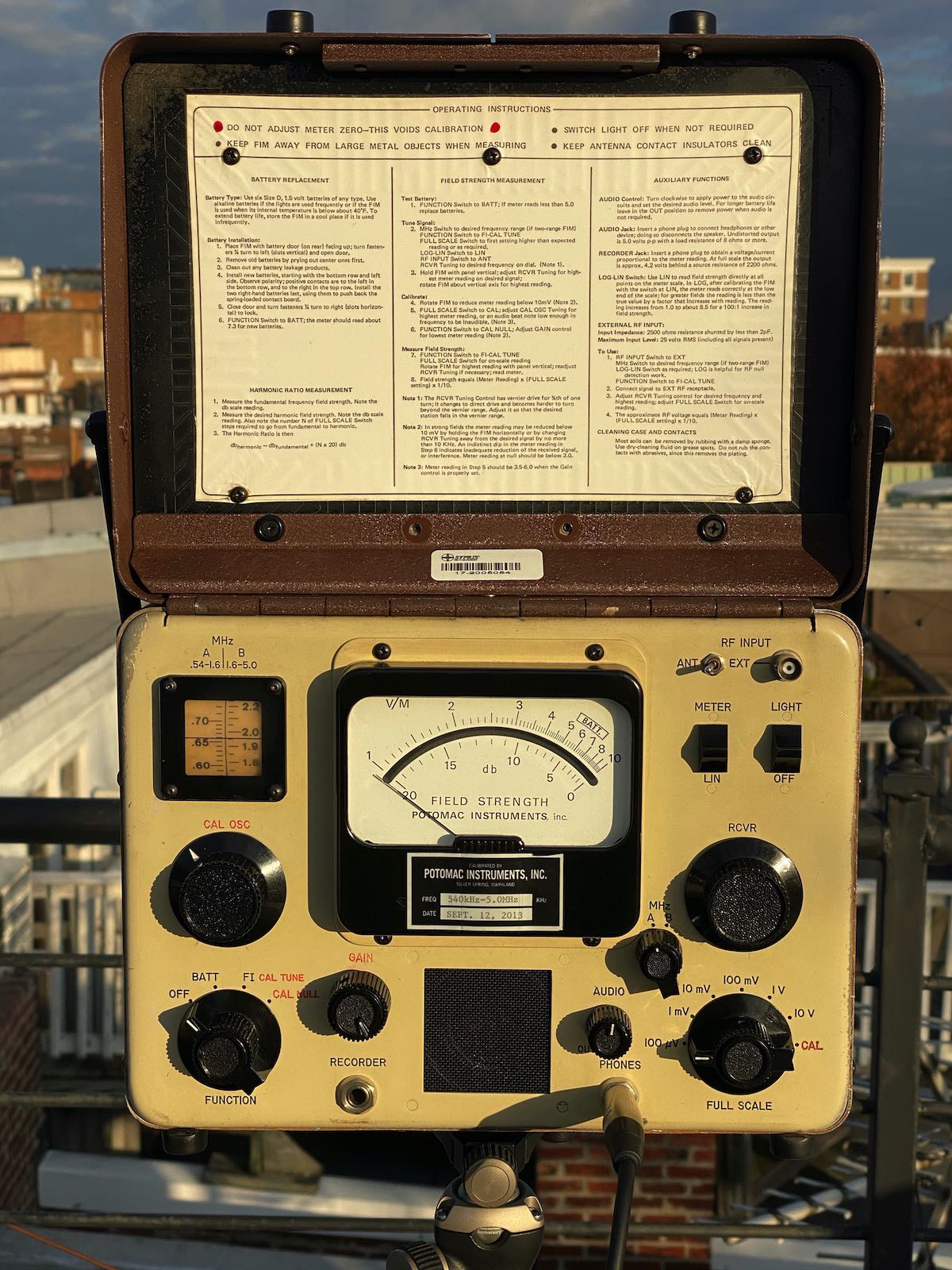
  • Potomac Instruments FIM-41 Field Intensity Meter (my personal favorite)
  • Panasonic RF-2200
  • Sony IC-EX5MK2
  • C.Crane Radio 2E
  • Sangean PR-D4W
  • Sangean ATS-909X
  • Tecsun PL-990X
  • XHDATA D-808

I recorded two signals, one at night and one during the day.

Nighttime Signals

The first was at night: WWL New Orleans on 870 KHz. This signal is usually weak to medium strength here, but is a challenge for two reasons: first, it shares the frequency with Cuba’s Radio Reloj, and it is squeezed between two much higher strength signals: Toronto’s CJBC on 860, and NYC’s WCBS on 880. So you need a decent receiver and careful antenna orientation to receive it well here. That said, everything did pretty well, though you can see that some radios did better than others.

The mix

Solo tracks

Icom IC-R9500

Potomac Instruments FIM-41 Field Intensity Meter

Panasonic RF-2200

Sony IC-EX5MK2

C.Crane Radio 2E

Sangean PR-D4W

Sangean ATS-909X

Tecsun PL-990X

XHDATA D-808

Daytime Signals

The second signal was during the day and was MUCH more marginal: WRJR Claremont, VA on 670 KHz. This was real challenge for any receiver and antenna. The signal was weak, and overshadowed by WCBM Baltimore on 680, a 50KW daytimer that is very strong here. (I’m not 100% sure that we were actually listening to WRJR – I never got an ID, but the station format and signal bearing was right). We can really hear some differences between the radios here.

The mix

Solo tracks

Icom IC-R9500

Potomac Instruments FIM-41 Field Intensity Meter

Panasonic RF-2200

Sony IC-EX5MK2

C.Crane Radio 2E

Sangean PR-D4W

Sangean ATS-909X

Tecsun PL-990X

XHDATA D-808

Everything (except the Icom) was powered by batteries and used the internal MW wave antenna, oriented for best reception by ear (not just maximizing signal strength, but also nulling any interference). The loop for the Icom was similarly oriented for best intelligibility.

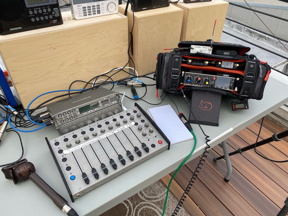
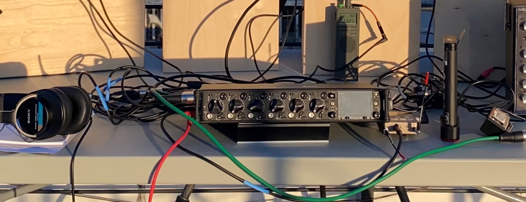
For audio nerds: The recording setup involved a lot of gear, but made it fairly easy to manage capturing so many inputs at once. The portable radios were all connected to a Sound Devices 788T recorder, with levels controlled by a CL-9 linear mixing board control surface. This both recorded the solo tracks for the portables as well as providing a rotating mix signal for each receiver that was sent to the next recorder in the chain, a Sound Devices 833. The 833 received the mix audio from the 788T, which went directly to the right channel. The left channel on the 833 got audio from a Lectrosonics 822 digital wireless receiver, which had the feed from the Icom R-9500 in the shack (via a Lectrosonics DBu transmitter). The center channel on the 833 for narration of the mix, which I did with a Coles 4104B noise-canceling ribbon mic. This let me record fairly clean audio in spite of a fairly noisy environment with some wind.

All the radio tracks were recorded directly off the radios’ audio line outputs, or, if no line out was available, from the speaker/headphone jack through a “direct box” interface. I tried to make the levels as close to equal as I could, but varied band conditions and different receiver AGC characteristics made it difficult to be completely consistent.

Making the recordings was pretty easy once it was set up, but it did involve a turning a lot of knobs and moving faders in real time. I must have looked like some kind of mad scientist DJ to my neighbors, some of whom looked at me oddly from their own roofs.

Happy Thanksgiving weekend!


Thank you, Matt, for another brilliant audio comparison! I appreciate the attention and care you put into setting up and performing these comparisons–not an easy task to say the least. That Potomac Instruments FIM-41 is an impressive machine!

By the way, I consider it a badge of honor when the neighbors look at me as if I’m a mad scientist. I’m willing to bet this wasn’t your first time! 🙂

Post readers: If you like this audio comparison, please check out Matt’s previous posts as well:

CQ Satellite: ARISS FM Repeater, Ham Sats, Tracking, Antennas, and Looking At The Future

Many thanks to SWLing Post contributor, Dan Van Hoy (VR2HF), who shares the following guest post:


ARISS FM Repeater May Be Back on Early December and a Short Ham Satellite Summary

by Dan Van Hoy (VR2HF)

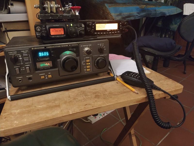
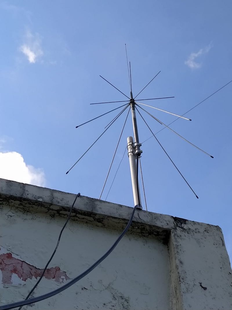
I’ve recently had a lot of fun learning about the current batch of ham satellites and operating through some of them for the past several months with only a Diamond discone (and a short run of RG-213 double-shielded coax), Yaesu FT-817 (for SSB/CW) and TYT TH-9800 for FM satellites (more power, Scotty!). This simple set-up has yielded hours and hours of great fun. The last time I did satellite work was in the ’70s making contacts from my car through Oscar 6. If I had a car here in Hong Kong I might try it again!

Here’s my living room TV tray and sofa shortwave and satellite station (no XYL in house at the moment).

ARISS FM Repeater

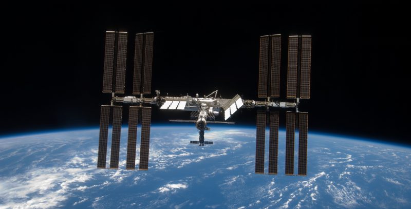
One of the recent highlights for both newcomers to satellite operations and old-timers was working the International Space Station’s (ISS) new FM repeater which came on the air in early September. It is a specially modified Kenwood D710-GA VHF/UHF transceiver. Unfortunately, it was only operational for about a month. For the past several weeks it has been used mostly in APRS mode.

The ARISS FM repeater runs five watts and sounds just like a regular terrestrial repeater in many ways. You can work it with any dual-band VHF/UHF FM rig and the right antenna. Full-duplex is not required, but it helps. Lower power requires some kind of gain antenna, but receiving can be done with simple antennas.

The ARISS organization just updated the schedule for the ARISS operation with this announcement:

“Next mode change (cross band repeater) targeting early December.”

YEAH! What a nice Christmas present!

Here’s a link to the full ARISS information page:

https://www.ariss.org/current-status-of-iss-stations.html

ARISS QSO with E21EJC

Here’s a Youtube video of one of my ARISS contacts with E21EJC. It was right after he came back from his DXpedition hauling microwave gear and dishes out to the Thai countryside to work the QO-100 geosynchronous satellite. I tell him “welcome home and have a good rest.” Kob really is “Mr Satellite!” He has posted hundreds of Youtube videos of satellite contacts.

In addition, here is video of their HS0AJ/P special “portable” station antennas for QO-100. 10 GHz RX dish (downlink) and 2.4 GHz TX dish (the big one). I listened to Kob and his friend make several QSOs via the QO-100 WebSDR:

Amazing the things we hams do just to spray some RF in the right direction!

Beyond the ARISS: A Ham Satellite Summary

Presently, AO-91 is probably the most popular FM satellite, along with SO-50, AO-27 and PO-101. RS-44, a linear satellite for SSB and CW, is far and away the most popular for those modes. RS-44 is in a higher orbit providing less Doppler shift and longer contact times per pass. You can easily see from the Amsat status page which satellites are in operation and which are the most popular. Many of the ham satellites do not provide two-way communication capability, but still have beacons (CW and data) that can be heard (those are in YELLOW on the Amsat status page). Everyone with a ham callsign can contribute by by uploading a reception report of the satellites you hear or work.

Full-duplex on SSB/CW satellite work is very desirable but not mandatory. I have learned you can make contacts without it coupled with a little skill and some luck. Staying near the center of the satellite’s particular passband is helpful. Sadly, there are few full-duplex rigs available these days. One of the best may be the Yaesu FT-847 which can be found on the used market. Some satellite ops are using SDRs for RX and a ham rig for TX to achieve full-duplex. I’m going to try that soon using two Diamond discones and vertical separation.

For current status of all ham satellites and ARISS operation, go here:

https://www.amsat.org/status/index.php

Tracking

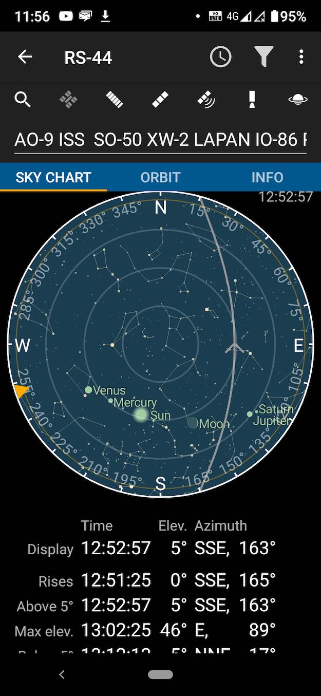
For tracking the ham sats and ISS, I like the Heavens-Above app (or Webpage: https://heavens-above.com/). The Pro version of Heavens Above is worth every penny. In the app, I put only the active satellites I am interested in in the search box. That way all the remaining unusable satellites will be ignored. Heavens-Above also lists the satellite operating frequencies for a quick reference.


One cool side note. With Heavens-Above, you can also see when ISS visible passes are available over your area (almost always near sunrise/sunset). Look for the passes with a magnitude greater than -3.0. If you have clear skies or a thin layer of clouds it’s quite a treat to see the ISS zoom overhead at 17, 000 miles per hour. When the ARISS repeater is operating, you can see and hear the ISS! The screen shot above is a visible pass at -3.9 magnitude, as bright as Venus.

Antennas

I have found my Diamond discone to work quite well for satellite operation. It’s probably the cheapest, simplest and most effective antenna you can use for this application If you really get interested in satellite work you can always spend the big bucks for AZ/EL rotators and beams as well as the software to run it all including tuning your rig to compensate for Doppler shift. Or you can buy quite expensive omni-directional antennas designed specifically for satellite use. So far, the KISS approach has worked well for me.

The Future Is Now

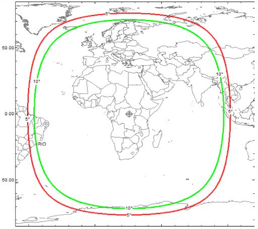
Finally, we can all get a taste of the future now by listening to the only ham radio geosynchronous satellite currently in operation, QO-100. It is centered on Europe and covers about 1/3 of the earth from Brazil to parts of Asia.

It was a thrill for me to listen (via the WebSDR listed below) to one of my new satellite colleagues, Mr Kob, E21EJC, who I call “Mr Satellite,” work Brazil and many other stations in the EU, the Middle-east and elsewhere through QO-100 during a special event operation from Thailand.

Anybody can listen to activity on QO-100 at the link below. When you get there just find the CLICK TO START SOUND! button. Then, click UNDER one of the signals in the waterfall and tune with the controls below. Weekends and holidays seem to be the best time to listen.

https://eshail.batc.org.uk/nb/

Because both the uplink and downlink frequencies are way up in the microwave bands, it’s not easy to get on QO-100, but, it appears to me, worth the effort. Maybe one day we will have two more QO-100-like birds linked together to cover the whole earth for 24/7 communication anywhere in the world. One can dream.

Full details about the QO-100 geosynchronous satellite can be found here:

https://amsat-uk.org/satellites/geo/eshail-2/

CQ Satellite!

When the propagation is bad, or actually anytime, ham satellites are a wonderful alternative to HF for having fun on the air.

Sorry, gotta go, RS-44 is just about here. CQ satellite, CQ satellite, de VR2HF…


Thank you so much for the satellite overview, Dan!

You’ve inspired me to get out of my comfort zone and try a little satellite work! The perfect project to do with my two daughters. I’m such a “below 30MHz” guy, I have to remind myself that there are actually some pretty amazing things you can do further up the band! When I purchase a discone antenna, I’m going to accuse you of being an enabler. Fair warning.

SWLing Post readers: Anyone else here tune to and track satellites? Please comment!

Paolo warns of persistent classifieds scams targeting radio collectors and advises how you can be scam savvy!

Many thanks to SWLing Post contributor, Paolo Viappiani (SWL I1-11437), who shares the following guest post:


A recent resurgence of Internet scams involving quality radios

by Paolo Viappiani (SWL I1-11437)

After my previous post on this subject, I found on the Internet other very dangerous fraud attempts concerning high-quality radios offered at very convenient prices. Below, you’ll find the details of a recent attempt concerning the highly-desirable SONY CRF-V21 receiver.

The methods are always the same, but the scammers greatly refine their fraudulent techniques, even going so far as to carry out real identity thefts, as in this case.

Of course, I knew from the beginning that it was a fraud (I don’t let myself be fooled anymore!), but I tried to continue corresponding with the scammer in order to get as much data on his real identity as possible. At the same time, however, I reported the fraudulent advertisement to the site webmaster in order to prevent other users from falling into the trap. The ad was promptly removed, but the scammer noticed it and immediately he slipped away…

Here is the story…

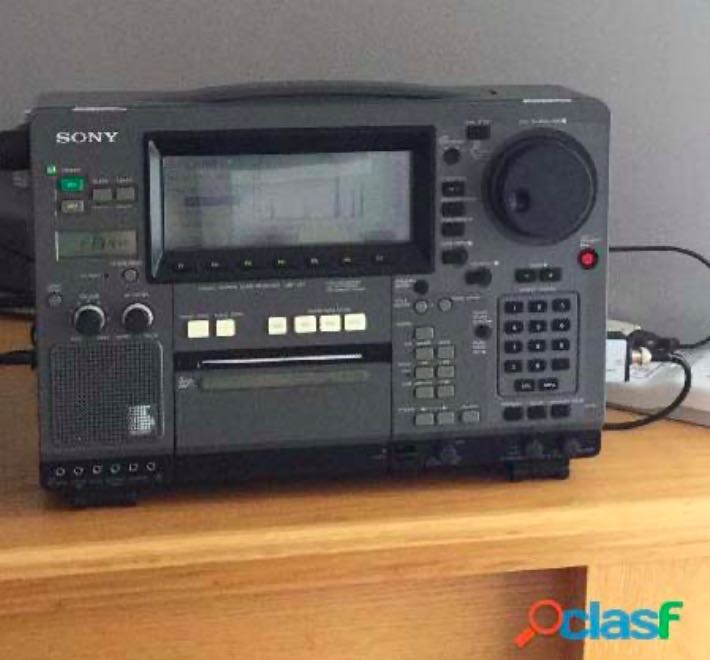
I have been trying to detect and report Internet scams from some time (since I was scammed!), and recently I found an advertisement for a SONY CRF-V21 radio, described as working and in good cosmetic conditions, on the Italian website “Clasf”, look at the picture below:

The radio was offered for Euro 2.600 from a seller who supposedly resided in Rome, Italy.

I sent him a message through the “Clasf” site and almost immediately I received a reply from someone who claimed to reside in Reichertshofen, Germany.

Déjà vu… Germany, Spain or Portugal always seems to be the same story…

But this time the very serious thing is the fact that the scammer identified himself as an “implantology dentist”–a fake identity–also providing a counterfeit website:

From my investigation it appears that both the picture and the website were stolen from a true professional from Hamburg, Dr. Bernhard Brinkmann, look at the websites (here and here).

Of course I tried to contact Dr. Brinkmann and I still make all the documents available to him, in case he wants to prosecute the thief.

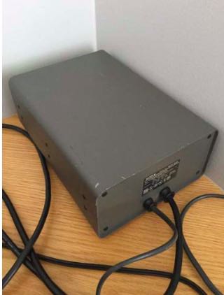
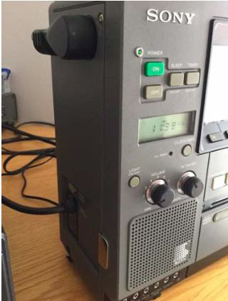
About the pictures I received from the scammer (you’ll find some of them below):

All photos were stolen from a Canadian eBay advertiser instead:

So, buyer beware! The number of frauds in the radio market on the Internet is growing day after day, and it always advisable to keep your eyes wide open, even in the rush to purchase a much desired item at an affordable price.

Today scam techniques are increasingly refined, as shown in the example reported above.
Sincerely I don’t know if this user has something to do with the other European scammers (supposedly from Spain and Portugal) I quoted in my former post. The Italian Postal Police, after having examined the headers of the e-mails that I received along with other documents, believe that such scammers can reside anywhere in the world.

Most scammed

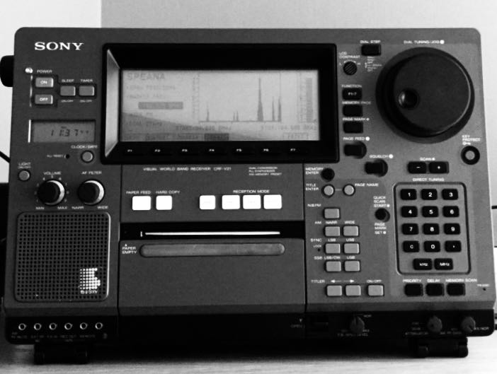
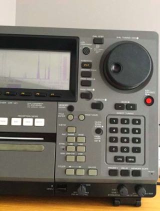
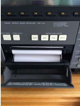
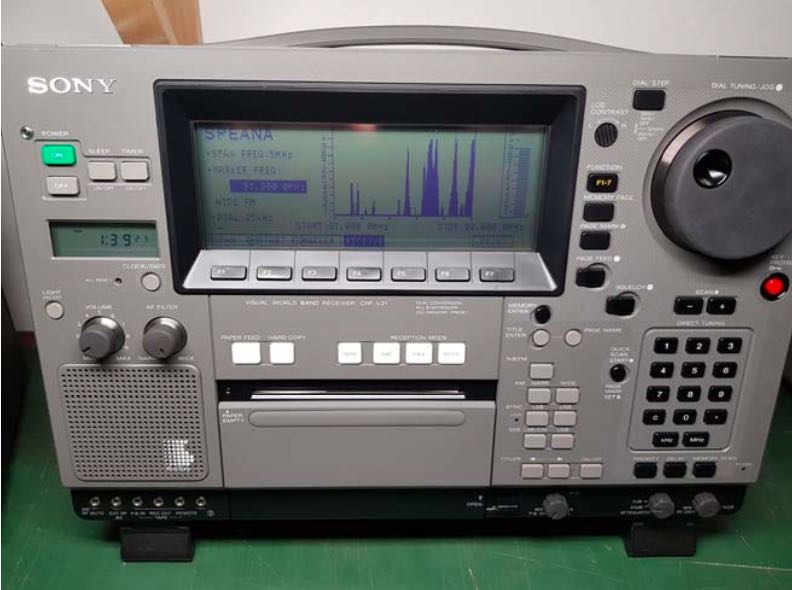
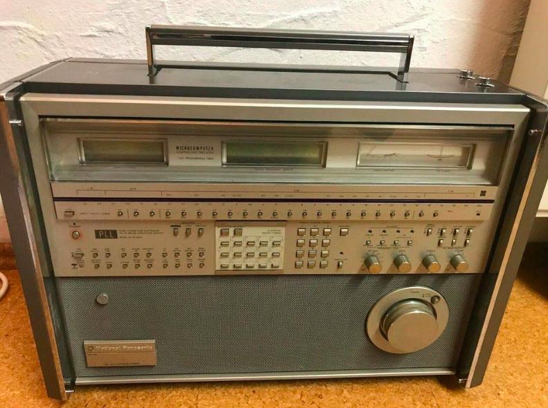
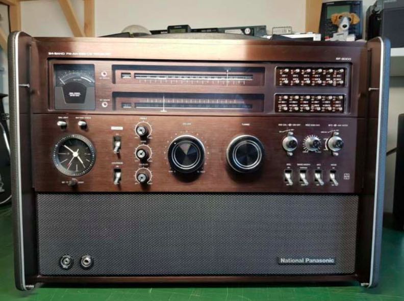
Anyway, the three “most scammed” radios are currently the Panasonic RF-8000, the Panasonic RF- 9000 and the Sony CRF-V21 (pictures below):

Please also notice that a number of advertisements on the most popular classifieds sites (Quoka.de and ebay-kleinanzeigen.de in Germany, Subito.it, Clasf and AAAnnunci.it in Italy, Le Bon Coin in France, ComoFicho in Spain, etc.) still are mirrors for larks only, and you have to pay a great attention in order not to be scammed.

A recent trip over all the mentioned sites revealed that only a few ads are really true…

Red Flags

I repeat some notes about scammers and their usual techniques:

A.) The scammer advertises a very rare radio in like-new conditions at an unbelievably low price. The buyer does not want to miss the bargain, so he contacts the seller and promptly transfers the money to him without further ado, but after that he waits in vain for the delivery of his item.

B.) If you contact the seller, the item is always abroad. The alleged seller then proposes to handle the purchase through a “trust company”. The radio should be paid in advance and the amount sent via cash transfer, but after that you never hear anything from the seller again.

C.) Alternatively, the buyer is requested to to deposit the money to the eBay company account to get the product. But the account is fake (eBay HAS NO “Company Account” and never handles private transactions!), so the buyer loses his money and receives nothing in return. Please also notice that often the fraudulent sellers offer a free period for evaluating the item, saying that if you do not like the device you can send it back. Please don’t fall into this trap, it is only one of the means the scammers use to entice you to purchase, but IT IS NOT TRUE AT ALL!

I repeat also some useful advices in order to make secure and safe purchases on the Internet:

1.) Always beware whenever the item is in a place (or a country) different from the one that was specified in the advertisement; also there is a valid reason for suspicion when the name or the address of the advertiser does not match the seller’s ones;

2.) Do not completely trust the pictures sent by the seller (they could be stolen from the Internet) and don’t forget to proceed to a “Google Reverse Image Search” in order to find the sources of similar ones;

3.) Always ask the seller for some specific pictures or videos (radio precisely tuned to various frequencies and/or modes) and do not accept any runarounds about it (“you can try the radio for some days”, etc.);

4.) Never pay the item in advance by rechargeable credit cards, Western Union or other non-secured/guaranteed ways of payment. Also Bank Transfer (Wire Transfer) is not a secure form of payment in order to avoid frauds;

5.) Always ask the seller for paying by PayPal “Goods and Services” (NOT “Send money to friends”); via “Goods and Services”, your purchase will be fully covered by the PayPal warranty.

In the case you are a victim of a scam anyway, please always report the incident to the Police or the Judiciary of your Country, and don’t forget to also warn the site where the announcement was found.

Best regards!
Paolo Viappiani – SWL I1-11437


Thank you so much for sharing this, Paolo! All very solid advice for avoiding scams. 

If you think about it, scammers want to optimize their scam profits per transaction–in other words, go for the “low-hanging fruit.” This is why quality, rare radios are their bait of choice. They know there are motivated collectors and buyers who need to act quickly in order to secure a deal. The stakes are very high if you’re purchasing a rare/vintage radio via online classifieds sites. 

Bookmark this article. Before making a radio purchase, re-read this post and follow Paolo’s advice. I promise: real vintage/rare radio sellers will happy take specific photos and videos in order to prove that the radio is indeed in their possession and that it functions as specified. If you receive an excuse–any excuse–from the seller, consider that a major read flag and do not proceed. 

Thank you again, Paolo! I hereby name you an honorary SWLing Post Investigative Reporter!


Do you enjoy the SWLing Post?

Please consider supporting us via Patreon or our Coffee Fund!

Your support makes articles like this one possible. Thank you!

Matt’s Marathon MediumWave Matchup

Many thanks to SWLing Post contributor, Matt Blaze (WB2SRI), who shares the following guest post:


Matt’s Marathon MediumWave Matchup

by Matt Blaze

Here’s another simultaneous receiver comparison, this time of ten portable medium wave receivers plus the Icom IC-R9500 (as a “reference receiver”). Previously, I used the same antenna for all the comparisons, but since these are portable receivers, I wanted to compare their performance using their built-in antennas. I did two comparisons, both of moderate to weak signals, one in the evening of a DX signal and the other in the daytime of a regional station.

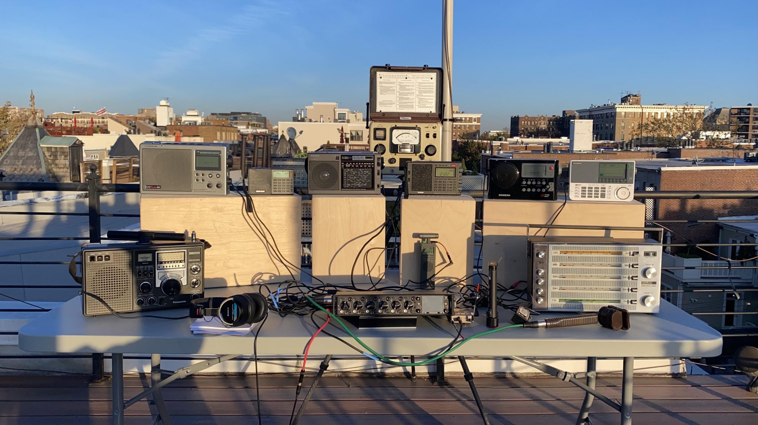
The receivers were the Potomac Instruments FIM-41 (a “field intensity meter”), the Panasonic RF-2200, the Nordmende GlobeTraveler Exec (a beautiful German SW portable from 1968), the Sony ICF-EX5MK2, the CCrane Radio 2E, the Sangean ATS-909X, the Sangean D4W, the new Tecsun PL-990X, the XHDATA D-808, and finally the CountyComm GP5-SSB, plus the Icom IC-R9500.

All the receivers were recorded simultaneously. The radios (except the Icom R9500) were on the roof of my building and oriented for best reception (signal/noise) and kept sufficiently away from each other and other metal objects to avoid interference, The R9500 was in the shack and used a Wellbrook loop on the roof, also oriented for best signal/noise. I took the audio from the Line Out if one was available and from the headphone jack (via a “direct box” level converter) if not. I tried to match the audio levels reasonably closely, but different ACG characteristics made it difficult to be completely consistent across all the receivers throughout the sessions.

As in previous comparisons, for each session I’ve got a narrated stereo mix with the R9500 on the left channel and each receiver, for a minute or so one after the other on the right channel. You definitely want to use headphones to listen to these so you easily tell the left from the right radio. I’ve also provided mono “solo” recordings of each receiver for the full 15 minute-ish sessions so you can hear a receiver you’re interested in in detail.

Sound Devices 688 Multitrack Recorder

The recordings were made with a Sound Devices 688 recorder/mixer (which can record 12 simultaneous channels of audio). The portable radios were hardwired to the recorder, and the 9500 (which was downstairs) was connected via a Lectrosonics digital radio link. (Everything except the R9500 was on battery power to avoid mutual interference and ground loops, etc). The narration used a Coles noise canceling ribbon mic. Everything was done in a single take per session – there was NO postproduction editing – so I apologize for a few glitches and awkward moments.

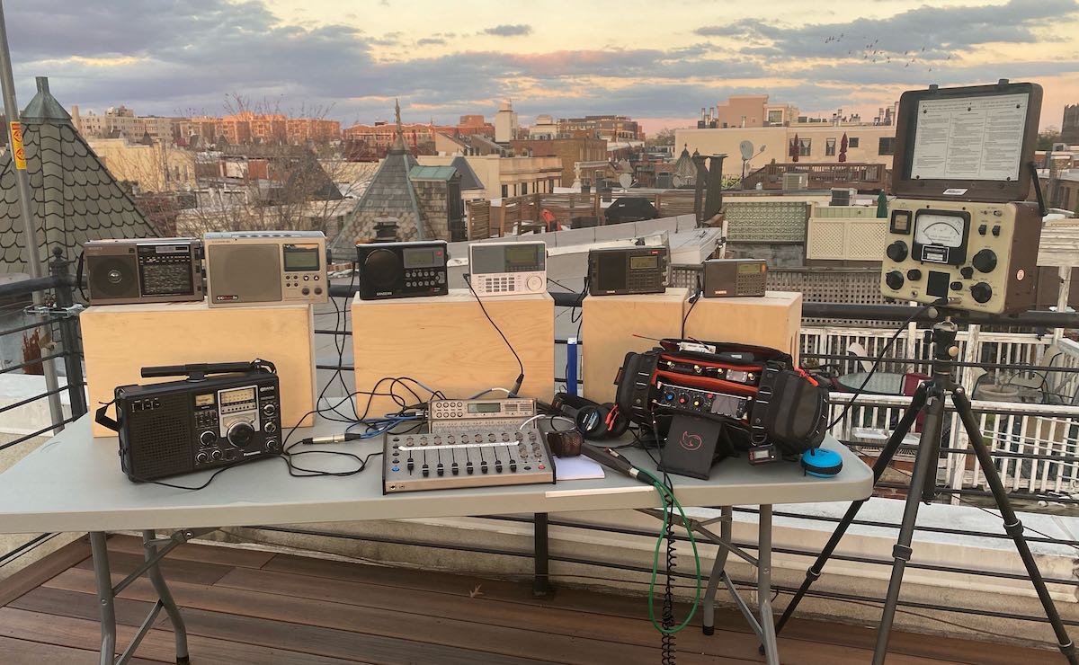
You can see a “class photo” of the setup below, although the position and orientation of the radios was different during the actual recordings.

KCJJ

The first recording was at night, where we tuned to 1630 KCJJ in Iowa City, IA. This is effectively a 1KW clear channel; other than a few TIS stations, there’s not much else there on the east coast, and the signal is reliably weak to moderate but readable here on the east coast.

Narrated L/R stereo comparison:

Individual solo tracks:

CCrane Radio 2E

Sangean D4W

XHDATA D-808

Sony ICF-EX5MK2

Potomac Instruments FIM-41

CountyComm GP5-SSB

Nordmende GlobeTraveler Exec

Tecsun PL-990X

Icom IC-R9500

Panasonic RF-2200

Sangean ATS-909X


WSVA

The next recording was made during the day, of WSVA, a regional station in Harrisonburg, VA running 5KW in the daytime. Their signal is also reliably weak-moderate but readable here.

Narrated L/R stereo comparison:

Individual solo tracks (receiver should be obvious from the file name):

CCrane Radio 2E

Sangean D4W

XHDATA D-808

Sony ICF-EX5MK2

Potomac Instruments FIM-41

CountyComm GP5-SSB

Nordmende GlobeTraveler Exec

Tecsun PL-990X

Icom IC-R9500

Panasonic RF-2200

Sangean ATS-909X

Hope your readers find it useful!

-matt


An absolutely amazing job again, Matt! Thank you so much for taking the time to put this comparison together and sharing it here on the SWLing Post.  

Click here to check out all of Matt’s receiver audio comparisons.