 Many thanks to SWLing Post contributor, Paul Walker, who writes:
Wether you do AM, shortwave, longwave, FM or something else, I think this will prove useful.
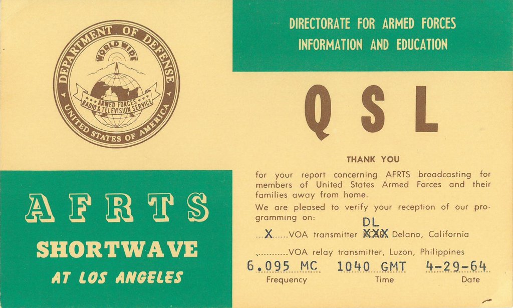
I have a pretty high return rate when submitting reception reports and asking for QSL cards/letters. I’d say my return rate is probably better than 60 percent, sometimes even 70 or 80 percent. It just depends.
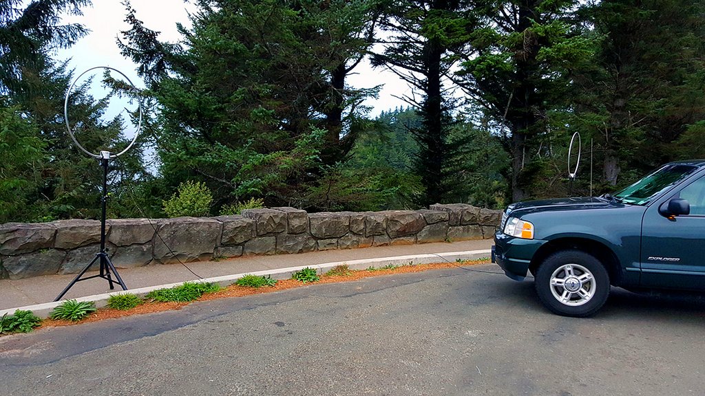
But what helps me so much? EVERY reception report I email or snail mail includes an audio recording. Sometimes it’s only 30 seconds if the signal is really rough, weak or hard to pick out anything useable. Sometimes I include anywhere between 5 minutes and 30 minutes with a detailed report.
Well, how do I record? I use my smartphone! I have an iPhone 6 Plus with 128 GB of storage. iPhones record some of the best audio I’ve ever heard from a smartphone. Androids do a pretty decent job–not as good, but not bad.
The best app I’ve found for this is Voice Recorder Pro 7.
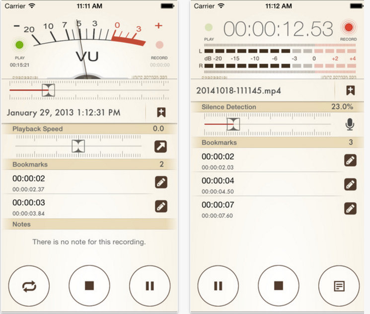
Voice Recorder Pro 7 Screenshots
You can select the recording format (mp4, mp3 or wav), you can select the sample rate, bit rate (32kbps all the way up to 320kbps), you can select mono or stereo as well.
But where this really comes in handy? You can email the audio file to yourself or someone with the click of a button, you can upload it to a google drive, dropbox, one drive or a box cloud account. You can even have it upload to an FTP server or to your Facebook page if you want!!
The one feature I like is being able to turn audio into a YouTube video and uploading it directly! I was recording videos by holding it up to the radio’s display and while the audio was good, it wasn’t great because it was a bit further away from the speaker so I could show the S meter and frequency on the display.
So what I ended up doing is to put the phone right near the radio’s speaker and start recording… this produces better audio then a straight up video. Then you click a button after the recording is over and it generates the video frames for you, putting a picture there; you fill in the particulars of your video and it uploads it to your YouTube account.
See what I’m talking about here, by viewing my YouTube account:
https://www.youtube.com/user/OnAirDJPaulWalkerYou can easily tell which videos were made by me holding up the phone to the radio’s display and which are audio only with the video generated by Voice Recorder Pro 7.
Here’s an audio only track I recorded to give you an idea how it sounds.
https://soundcloud.com/paul-walker-11/radio-mediterranne-international
I don’t recall if they have this app for Android phones, but if they don’t, there’s something similar. It’s worth investigating.
A detailed written report is one thing when requesting a QSL, but audio is indisputable and absolute confirmation of what was heard.
Many thanks for the recommendation, Paul. I use an Android phone (the Moto X 2nd generation). I’m hoping a Post reader can suggest a recording app that is equally robust.
Like you, I typically send an audio recording when submitting a reception report. It’s certainly a valuable piece of information for broadcast engineers. Thanks again!