Many thanks to SWLing Post contributor, Paolo Viappiani (SWL I1-11437), who shares the following guest post:
A recent resurgence of Internet scams involving quality radios
by Paolo Viappiani (SWL I1-11437)
After my previous post on this subject, I found on the Internet other very dangerous fraud attempts concerning high-quality radios offered at very convenient prices. Below, you’ll find the details of a recent attempt concerning the highly-desirable SONY CRF-V21 receiver.
The methods are always the same, but the scammers greatly refine their fraudulent techniques, even going so far as to carry out real identity thefts, as in this case.
Of course, I knew from the beginning that it was a fraud (I don’t let myself be fooled anymore!), but I tried to continue corresponding with the scammer in order to get as much data on his real identity as possible. At the same time, however, I reported the fraudulent advertisement to the site webmaster in order to prevent other users from falling into the trap. The ad was promptly removed, but the scammer noticed it and immediately he slipped away…
Here is the story…
I have been trying to detect and report Internet scams from some time (since I was scammed!), and recently I found an advertisement for a SONY CRF-V21 radio, described as working and in good cosmetic conditions, on the Italian website “Clasf”, look at the picture below:
The radio was offered for Euro 2.600 from a seller who supposedly resided in Rome, Italy.
I sent him a message through the “Clasf” site and almost immediately I received a reply from someone who claimed to reside in Reichertshofen, Germany.
Déjà vu… Germany, Spain or Portugal always seems to be the same story…
But this time the very serious thing is the fact that the scammer identified himself as an “implantology dentist”–a fake identity–also providing a counterfeit website:

From my investigation it appears that both the picture and the website were stolen from a true professional from Hamburg, Dr. Bernhard Brinkmann, look at the websites (here and here).
Of course I tried to contact Dr. Brinkmann and I still make all the documents available to him, in case he wants to prosecute the thief.
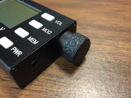
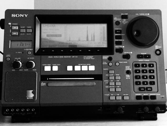
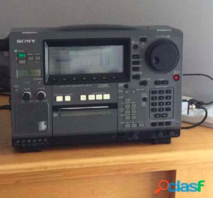
About the pictures I received from the scammer (you’ll find some of them below):
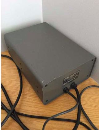
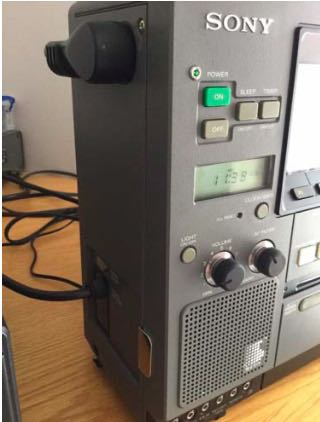
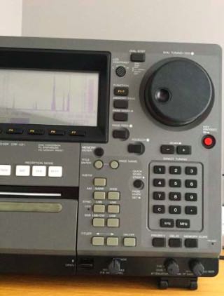
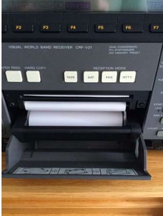
All photos were stolen from a Canadian eBay advertiser instead:
So, buyer beware! The number of frauds in the radio market on the Internet is growing day after day, and it always advisable to keep your eyes wide open, even in the rush to purchase a much desired item at an affordable price.
Today scam techniques are increasingly refined, as shown in the example reported above.
Sincerely I don’t know if this user has something to do with the other European scammers (supposedly from Spain and Portugal) I quoted in my former post. The Italian Postal Police, after having examined the headers of the e-mails that I received along with other documents, believe that such scammers can reside anywhere in the world.
Most scammed
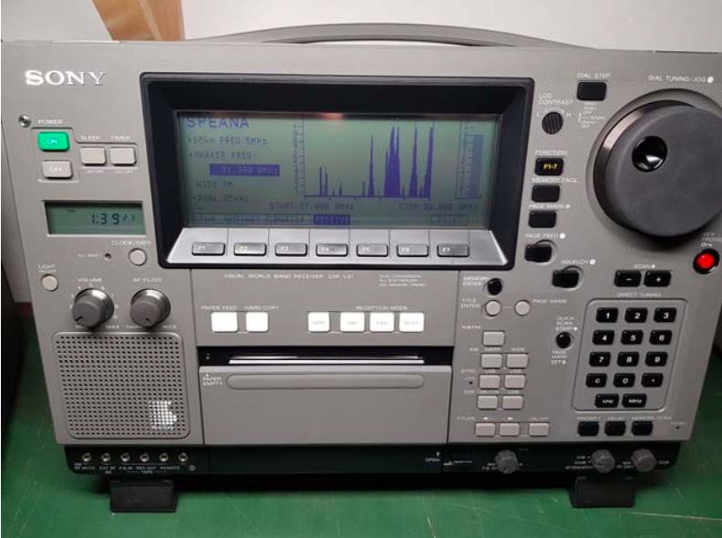
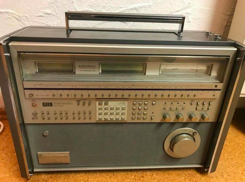
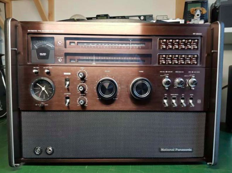
Anyway, the three “most scammed” radios are currently the Panasonic RF-8000, the Panasonic RF- 9000 and the Sony CRF-V21 (pictures below):
Please also notice that a number of advertisements on the most popular classifieds sites (Quoka.de and ebay-kleinanzeigen.de in Germany, Subito.it, Clasf and AAAnnunci.it in Italy, Le Bon Coin in France, ComoFicho in Spain, etc.) still are mirrors for larks only, and you have to pay a great attention in order not to be scammed.
A recent trip over all the mentioned sites revealed that only a few ads are really true…
Red Flags
I repeat some notes about scammers and their usual techniques:
A.) The scammer advertises a very rare radio in like-new conditions at an unbelievably low price. The buyer does not want to miss the bargain, so he contacts the seller and promptly transfers the money to him without further ado, but after that he waits in vain for the delivery of his item.
B.) If you contact the seller, the item is always abroad. The alleged seller then proposes to handle the purchase through a “trust company”. The radio should be paid in advance and the amount sent via cash transfer, but after that you never hear anything from the seller again.
C.) Alternatively, the buyer is requested to to deposit the money to the eBay company account to get the product. But the account is fake (eBay HAS NO “Company Account” and never handles private transactions!), so the buyer loses his money and receives nothing in return. Please also notice that often the fraudulent sellers offer a free period for evaluating the item, saying that if you do not like the device you can send it back. Please don’t fall into this trap, it is only one of the means the scammers use to entice you to purchase, but IT IS NOT TRUE AT ALL!
I repeat also some useful advices in order to make secure and safe purchases on the Internet:
1.) Always beware whenever the item is in a place (or a country) different from the one that was specified in the advertisement; also there is a valid reason for suspicion when the name or the address of the advertiser does not match the seller’s ones;
2.) Do not completely trust the pictures sent by the seller (they could be stolen from the Internet) and don’t forget to proceed to a “Google Reverse Image Search” in order to find the sources of similar ones;
3.) Always ask the seller for some specific pictures or videos (radio precisely tuned to various frequencies and/or modes) and do not accept any runarounds about it (“you can try the radio for some days”, etc.);
4.) Never pay the item in advance by rechargeable credit cards, Western Union or other non-secured/guaranteed ways of payment. Also Bank Transfer (Wire Transfer) is not a secure form of payment in order to avoid frauds;
5.) Always ask the seller for paying by PayPal “Goods and Services” (NOT “Send money to friends”); via “Goods and Services”, your purchase will be fully covered by the PayPal warranty.
In the case you are a victim of a scam anyway, please always report the incident to the Police or the Judiciary of your Country, and don’t forget to also warn the site where the announcement was found.
Best regards!
Paolo Viappiani – SWL I1-11437
Thank you so much for sharing this, Paolo! All very solid advice for avoiding scams.
If you think about it, scammers want to optimize their scam profits per transaction–in other words, go for the “low-hanging fruit.” This is why quality, rare radios are their bait of choice. They know there are motivated collectors and buyers who need to act quickly in order to secure a deal. The stakes are very high if you’re purchasing a rare/vintage radio via online classifieds sites.
Bookmark this article. Before making a radio purchase, re-read this post and follow Paolo’s advice. I promise: real vintage/rare radio sellers will happy take specific photos and videos in order to prove that the radio is indeed in their possession and that it functions as specified. If you receive an excuse–any excuse–from the seller, consider that a major read flag and do not proceed.
Thank you again, Paolo! I hereby name you an honorary SWLing Post Investigative Reporter!
Do you enjoy the SWLing Post?
Please consider supporting us via Patreon or our Coffee Fund!
Your support makes articles like this one possible. Thank you!