 Many thanks to SWLing Post contributor, Zack Schindler, who shares the following stories all focused on US broadcasters receiving pressure from the NAB and their communities to halt broadcasts of Russian state-sponsored media like Russia Today and Sputnik:
It says it is a “fierce defender” of the First Amendment and “the critical importance of the ability to freely express views, both popular and unpopular.”
That said, the NAB explains that the First Amendment “does not prevent private actors from exercising sound, moral judgment.”
That’s why the chief advocacy group for broadcast radio and TV wants any state-sponsored programming with ties to Moscow pulled from U.S. airwaves now.
What will operators in Kansas City and Washington, D.C., do? RBR+TVBR heard from one of them, and he’s livid with the NAB. Another has placed the association among those responsible for “Cancel Culture” in the U.S.
In response to the invasion of Ukraine by Russia, NAB President/CEO Curtis LeGeyt seemingly took aim at Sputnik, the English-language service of the Voice of Russia.
Sputnik has already noticed, and reacted. On Tuesday, it noted that “Western governments” and internet giants including Google, Microsoft, Facebook and Twitter “have moved to heavily censor Russian foreign-language media outlets over the conflict in Ukraine, blocking websites, shutting down social media pages, and taking radio and television broadcasts off air.”
Calling the “censorship” unacceptable, Russian Foreign Ministry spokesman Oleg Gavrilov said in a meeting of the Russian Federation Council that, “separately, attention should be paid to the absolutely unacceptable behaviour of foreign, especially American, IT giants such as Google and Meta. Hostile propaganda activities are openly conducted on their social platforms, while Russian sources of information are blocked, and massive restrictions on access to domestic media are put in place.”
[…]“[G]iven the unprovoked aggression exhibited by Russia against the free and sovereign people of Ukraine, NAB calls on broadcasters to cease carrying any state-sponsored programming with ties to the Russian government or its agents,” LeGeyt said. “While we know that airings of such programs are extremely limited, we believe that our nation must stand fully united against misinformation and for freedom and democracy across the globe.”
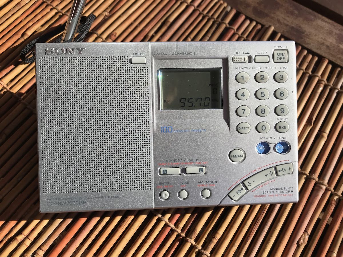
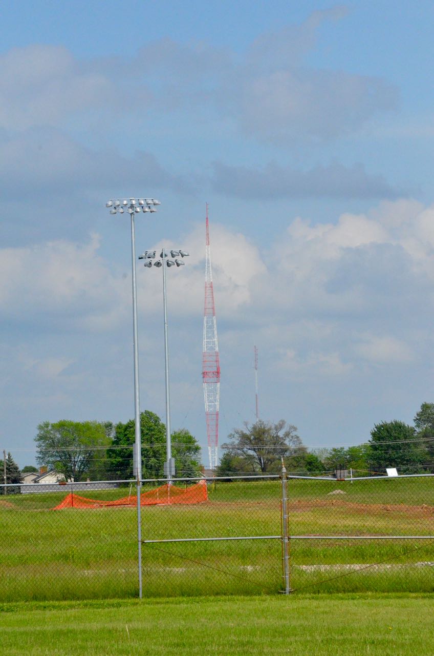
Programs aren’t extremely limited to those in the Nation’s Capital, where Radio Sputnik airs on W288BS, at 105.5 MHz, and originating station WZHF-AM 1390, a directional two-pattern Class B facility first known as Top 40 WEAM. Both WZHF and the FM translator reaches much of greater Washington. [Continue reading…]
“You’re listening to Radio Sputnik,’‘ the polished, made-for-radio voice says, accompanied by triumphant Russian-themed music. “Telling the untold.”
“Live from the divided states of America,” announces the host of “Fault Lines Radio” show. Produced in Washington, D.C., the program airs locally on AM radio station KCXL. Yes, we’re talking about a radio station spouting Russian propaganda from the heartland — just outside Kansas City. And why, you might ask, are Russian talking points airing on area radio stations?
Money talks. Or maybe we should say rubles.
Radio Sputnik, a media service funded by the Kremlin, airs daily on three stations in Kansas City. Alpine Broadcasting Corp. owner Peter Schartel is paid by Russian interests to broadcast pro-Vladimir Putin programming on them all.
And this week, with Russian tanks, artillery and troops continuing the tragic and reckless invasion of neighboring Ukraine, the Russian apologists spun hard. Schartel remained defiant even after multiple reports Thursday that the American branch of RT, the Russian-funded media network, was shutting down and laying off its staff. He said his contract was with an American company that works with the Russian authorities behind Sputnik. That company “has not notified us of any interruption,” he said.
For now, at least, the show goes on, and we sampled its absurd pro-Russian arguments so you wouldn’t have to.
Guests on the “Fault Lines Radio” show this week, encouraged by hosts Jamarl Thomas and Faran Fronczak, would have you believe Putin was an unwilling participant in this conflict. The Western media, one guest said, is complicit in spreading Ukrainian government war propaganda, and added that the besieged Ukrainian government is winning the information war on social media.
“If you were reading that, you might think there has been a billion Russian troops killed and that Ukrainian freedom fighters are storming Moscow,” said Mark Sleboda, Putin’s Moscow-based mouthpiece and frequent contributor to pro-Russian media companies.
Thomas predictably agreed, and the Putin praise continued.
KCXL has no ties to Russia and is against the country’s conflict with Ukraine, Schartel told us Wednesday. But he needs the money, and he’d lose his business if he pulled the plug on Radio Sputnik. So, that’s how you end up with a radio show here in the land of barbecue and jazz playing Cold War oldies and coddling a powerful, seemingly deranged dictator.
Putin ordered the invasion of neighboring Ukraine. The unprovoked and inhumane attack has caused thousands of deaths of both civilians and soldiers in Ukraine. Parts of the country are being reduced to rubble.
Outside of Moscow, the Russian invasion has been almost universally condemned. Except for right here in the Kansas City area, where listeners of KCXL were bombarded with pro-Putin talk. [Read the full article here…]
LIBERTY, Mo. —Down a rural road just a mile away from Liberty’s city square, a radio station inside small brick building displays an American flag in the front window.
For six hours every weekday, 1140AM KCXL broadcasts radio programming paid for by the Russian government, called Radio Sputnik.
The National Association of Broadcasters earlier this week called for U.S. broadcasters to cease Russian-sponsored programming considering the war in Ukraine.
[…]Alpine Broadcasting Programming and sales manager Jonne Santoli-Schartel told KMBC on Thursday she and her husband, Peter Schartel, have no plans to pull Radio Sputnik from the station’s airwaves.
“If we can’t express our viewpoints anymore, and we have cancel culture, and people deleting and people putting pressure on other people to not hear certain programming, then we’re in trouble and freedom no longer exists,” Santoli-Schartel said.
Those living nearby disagreed.
“If the money means more than your morals, then you’ve got a problem,” said Debbie Bowman, who has family members from Ukraine.
Last year, government documents showed Alpine Broadcasting made at least $60,000 from RM Broadcasting, led by Florida businessman Arnold Ferolito. RM Broadcasting acts as a go between for two U.S. radio stations including KCXL, and Rossiya Segodnya, a media organization sponsored by the Russian government.
A judge in 2019 ordered RM Broadcasting to register as a foreign agent under the U.S. Foreign Registration Act.
That act makes sure people engaged in domestic political or advocacy work on behalf of foreign interests disclose financial information along with relationships.
[…]Santoli-Shartel also said she does not agree with the Russian invasion of Ukraine, however, she has no plans to stop broadcasting.
“My heart is breaking for these moms and these dads on both sides,” she said. “I think if I was in Russia, I would want to get out of Russia because I think they’re in danger also. But the people of Ukraine, I think it is so horrible.”
To see RM Broadcasting’s latest filing under the Foreign Agent Registration Act, click here. [Read full article and view video here…]

 Many thanks to SWLing Post contributor, Tim Brockett, who writes: