Many thanks to SWLing Post contributor, TomL, who shares the following guest post:
Magnet Wire Vertical Loop Antenna
by TomL
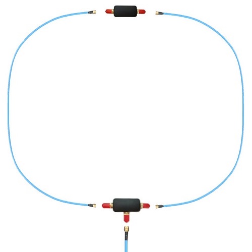
For those of you in a noisy condo like me, the environment does not give me many options. I was experimenting with a YouLoop on the wooden porch with somewhat acceptable results. For its size, it is an excellent performer, especially on the lower bands. Here is a very interesting review of the YouLoop, including close-up pictures of the innards of the phase inverter and 1:1 balun, by John S. Huggins. However, it is not waterproof and I was concerned about the ice and snow ruining it. I could tape up the connectors with waterproof tape but I also wanted something with a bigger capture area. A magnet wire stealth antenna might be just the thing!
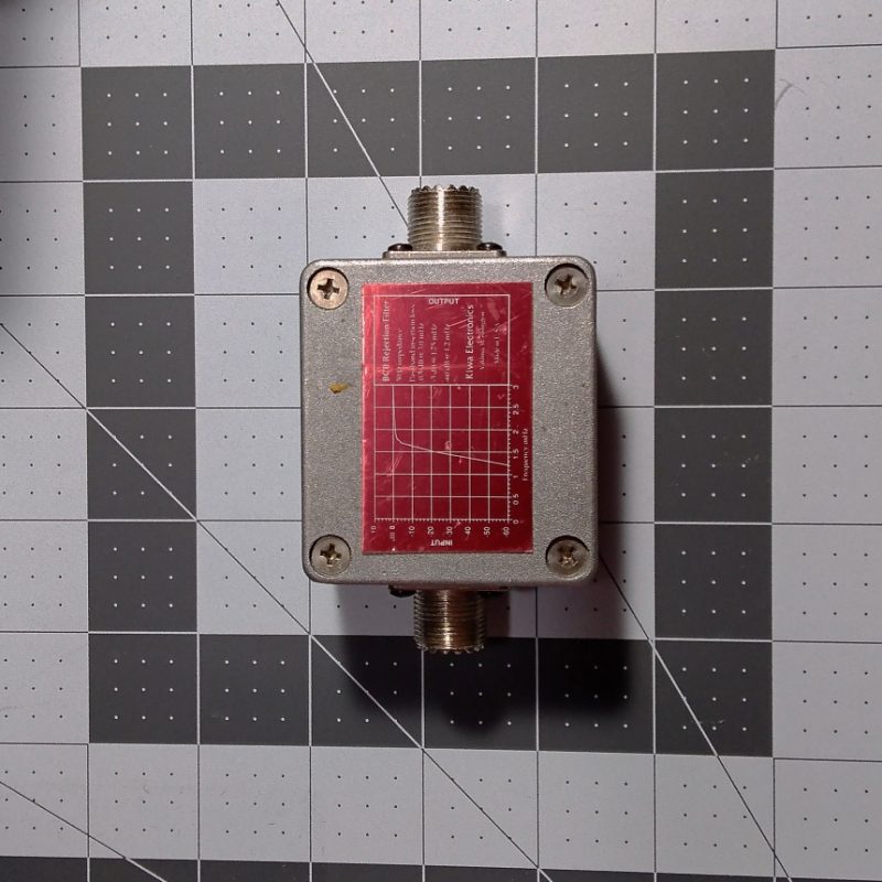
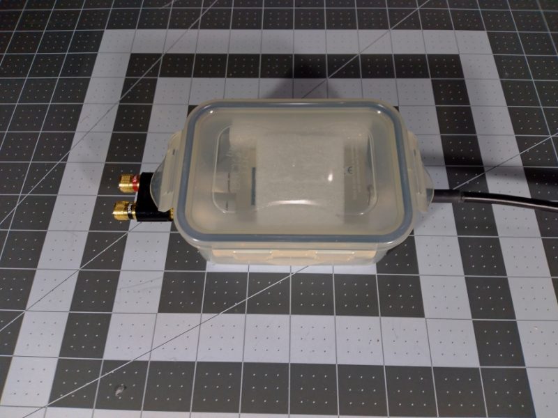
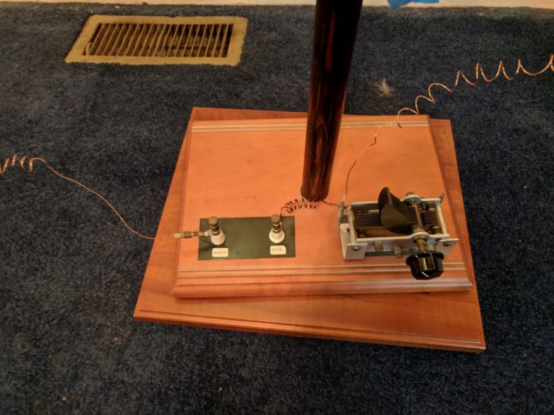
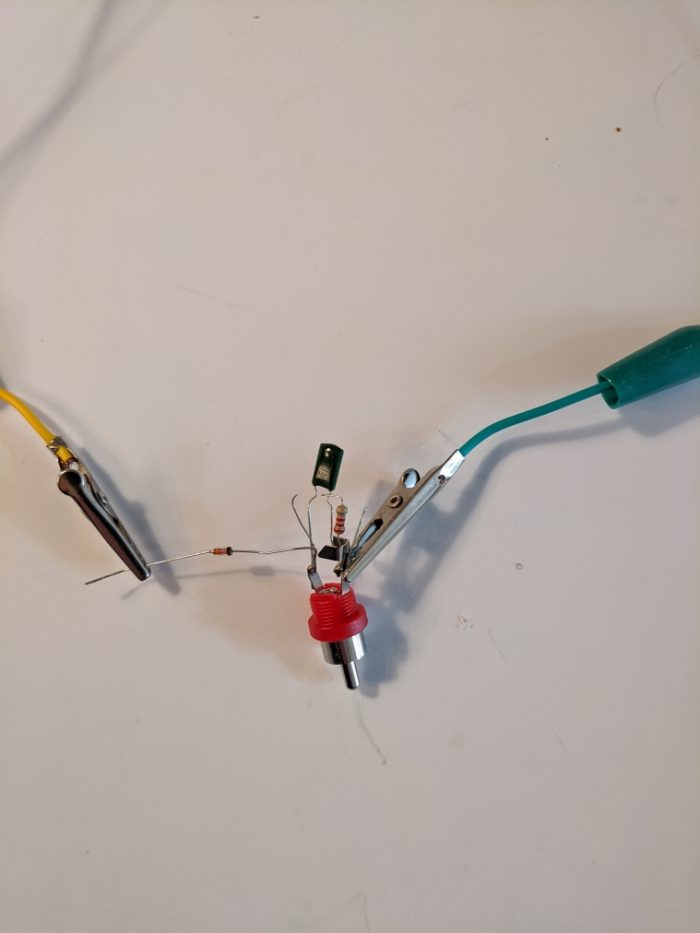
I just happened to have a waterproof 1:1 ATU balun from Balun Designs that I was going to use for future Amateur Radio use whenever I get around to passing the next level test; it is total overkill for what I intended to use it for. It would make a good connection point and (this one) also acts as an RF choke as well. One can make a 1:1 balun by buying the right Type of ferrite core and winding it yourself. Here is just one idea from Palomar Engineers.
So I dusted it off, went to a local store to get a 100 foot spool of 26 gauge magnet wire and tested it strung up around my living room. It came out to be a rectangle about 42 feet in circumference. Results were usable. I expected lots of noise and there is a great deal across the bands, so only the strongest shortwave stations were received. However, I was surprised by how strong the mediumwave band was and good to listen to without an amplifier.
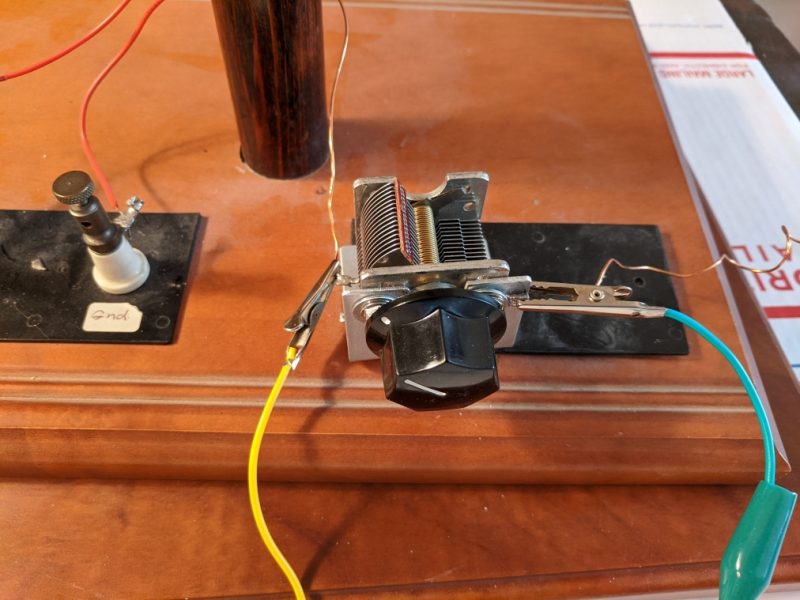
I am ambivalent towards trying to perfectly match the impedance since this is a broadband receive-only antenna and the impedance will vary greatly over MW and SW bands. And I don’t want to mess with a remotely controlled tuned loop since this antenna was destined for the outdoor porch. I tried a Cross Country Wireless preselector at my desk but had some mixed results. I later found out, by disconnecting things in series, that the preselector inline raised the noise level about 5 dBm, so I took it out for now. Perhaps it needs more internal shielding or the connecting cable is bad.
Polarization is an issue, too. I have read that most man-made noise (QRM) is vertically polarized, so why would I use a vertically oriented loop? Then I saw David Casler’s video on loop antennas where he explains that connecting a vertical loop antenna at the bottom or the top makes it horizontally polarized (connecting the coax on the side makes it vertically polarized). I never knew that! Horizontal polarization will mitigate some of the offending QRM as well as match the polarization of mediumwave band transmitters. Furthermore, I read that a horizontal loop will have poor signal pickup at low frequencies because it is not high enough off the ground, similar to a horizontal dipole. For now, a vertical loop connected to facilitate horizontal polarization is what I want.
A note about wire size. People make a big deal about it but those are mostly amateur radio people. Transmission depends on efficiency so things like wire size, skin effect, standing waves, and other things matter (see here, for example). With a receive-only antenna it is OK to use very thin wire. Resonance can matter if you want the last ounce of signal strength with an antenna tuner, like in high-Q type loops where the bandwidth is very narrow and you are using a multi-turn loop with variable capacitor and a pick-up coil of wire to the receiver. Comparatively, my simple loop is depending more on a single turn of wire, the aperture size, length of wire for its performance, and carefully isolating the feedline coax using RF chokes at both ends.
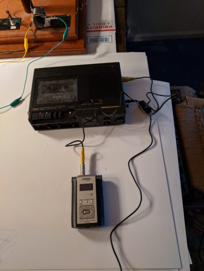
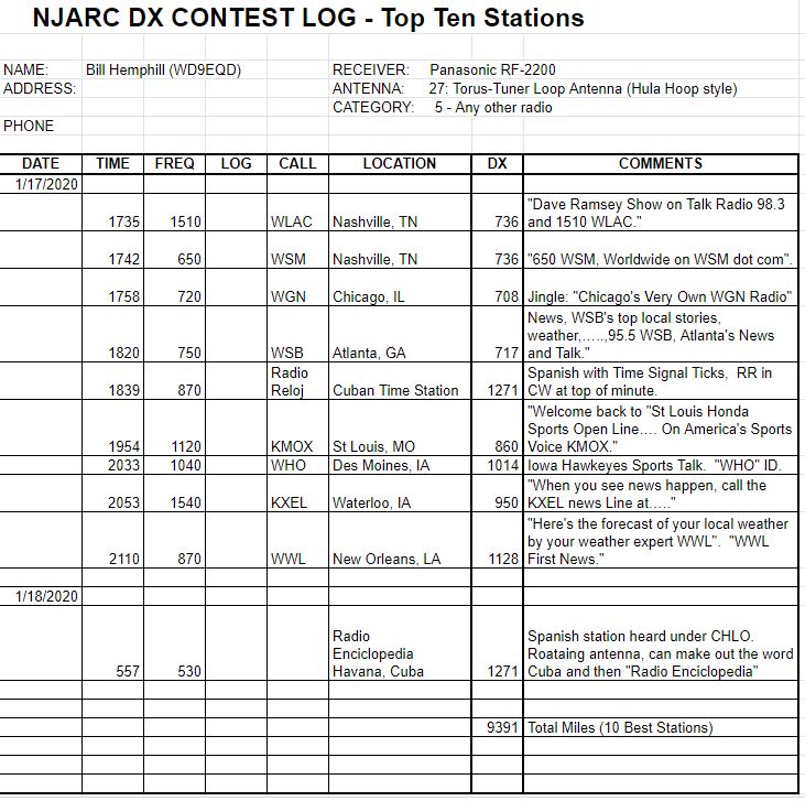
Here is one example of a strong station from Cuba I was able to record because WLW was off the air for some unexpected reason.
Radio Reloj, Cuba 870 kHz (At the end, you can hear WLW come back online with CBS news):
Side note about Radio Reloj on Wikipedia, the strange format seems to fit well with a totalitarian regime, including a “corrector” who “corrects the content/writing errors to meet the requirements”. Read the wiki link for yourself. Not a society I want to live in, thank you very much!
Example of 80 meter band performance – Greetings to a new person from members of the “Awful, Awful, Ugly Net”, 3855 kHz:
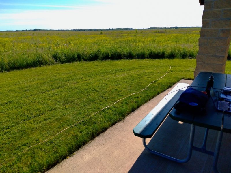
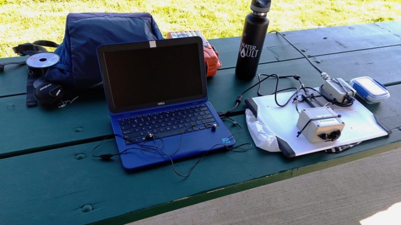
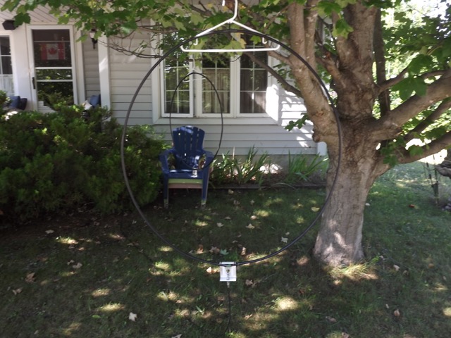
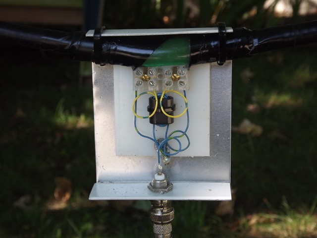
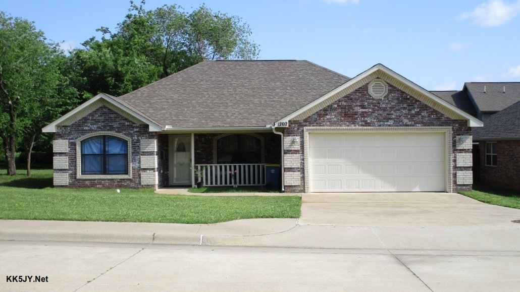
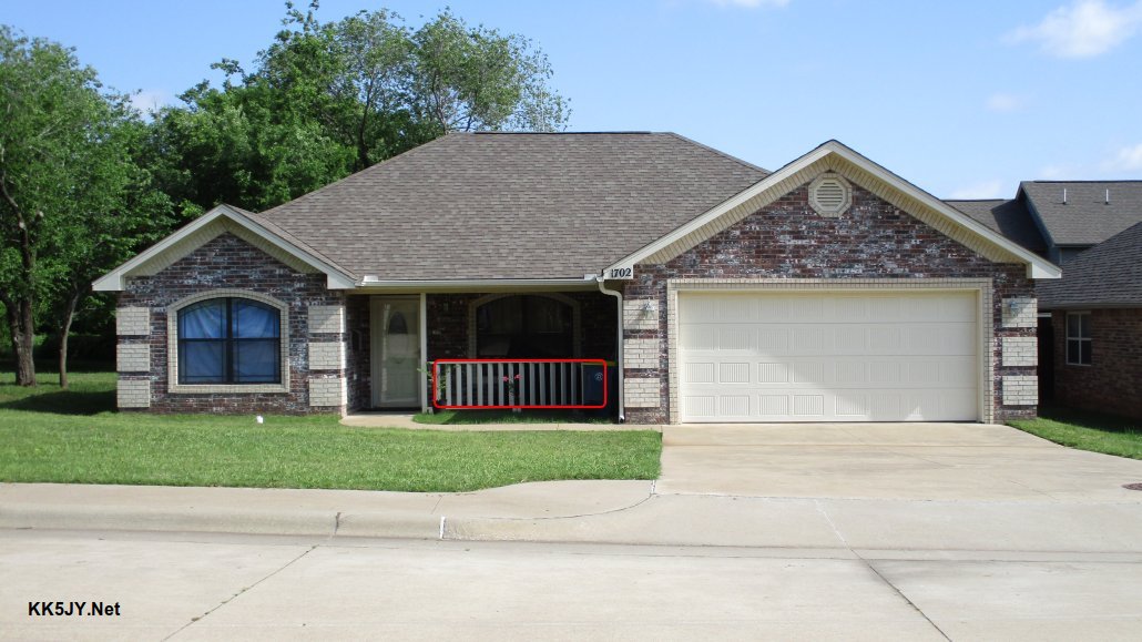
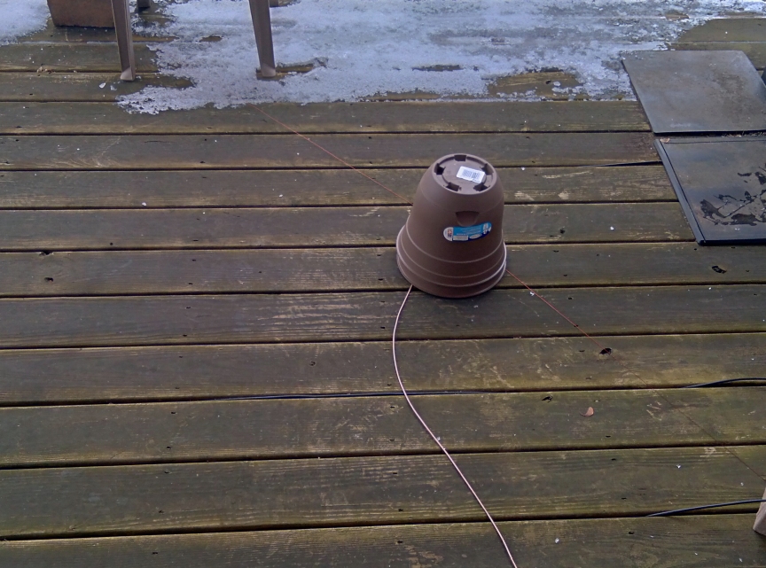
Encouraged by the results, I “installed” the magnet wire around the support beams of the wooden porch, wrapping it carefully to create a square loop. Holding it in place is a brick at each bottom corner since I am not allowed to nail anything into the Association-owned porch. The length came out to about 32 feet (8 feet per side), so I trimmed it and connected to the balun. I also added an RF choke at the Airspy HF+ input from Palomar Engineers which helped bring noise down a couple of S-units. That might not sound like a lot but by also shutting off the living room air filter and an AC switch with “wall-wart” AC power adapters on it, I was able to reduce the noise a little bit more. There is still a lot of noise from the neighbors, so it is not a perfect situation.
Here are two examples of reception with the outside installation.
Gateway 160 Meter Radio Newsletter, broadcast (in AM) by WA0RCR every Saturday on 1860 kHz:
Side note about the Radio Newsletter. I stumbled on it when using the YouLoop and found that some of the content is very interesting and informative. Of course it is geared mostly towards amateur radio but some of the news items are of general radio interest as well. It airs 1pm Saturday through 2am Sunday, USA Central Time. Obviously, many segments repeat during that lengthy timeframe and reception depends on propagation from Missouri.
KDDR 1220 kHz, West Fargo, ND station ID (presumably “nighttime” power of 327 watts):
The shortwave bands are still a noisy disaster but signal levels are higher compared to the YouLoop. Only the strongest stations come in like WRMI, WHRI, Radio Espana, Radio Habana, and CRI. And I can hear the loudest amateur radio operators.
Just for grins, here is Radio Rebelde on 5025 kHz when band conditions were above average:
Another phenomenon I am looking into is the reception pattern of a vertical loop. Less than 1/10th wavelength, the null is through the center of the loop. At one wavelength, the null manifests in the plane of the wire loop. They are too close to phase them but switching between two directional loop antennas might improve reception depending on frequency. We shall see in the future.
At least for now, I have a decent mediumwave band which performs better than the useful CCrane Twin-Ferrite amplified loop antenna that was used in the (noisy) indoors, I can hear the 160 & 80 meter amateur bands better, and the reception of the strongest shortwave broadcasters are more predictable. Not bad for four dollars of wire!
Brilliant, Tom! Again, I love how you’ve not only made an inexpensive antenna, but you’ve even done it within your HOA regulations. You’re right, too: if you’re not transmitting into an antenna, it blows the experimentation door wide open! Thank you once again for sharing your project with us.
Click here to check out all of Tom’s guest posts and portable adventures!