Tag Archives: SDR

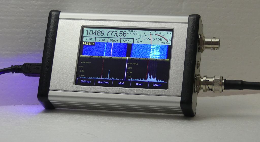
Check out the Afedri LAN-IQ SDR: a new stand-alone touch screen SDR

LAN-IQ SDR rev1.0 (Source: Alfredi SDR-Net)

Many thanks to SWLing Post contributor, Dan Robinson, who shares the following video from Fernando Duarte highlighting the new Alfredi LAN-IQ SDR:

I can’t wait to check out Fenu’s full review of the LAN-IQ when it is posted on his excellent website. The screen seems to be very responsive and layout well thought through.

The Afedri website notes the following features and specifications:

  • 30 kHz to 1700.00MHz continuous frequency range
  • Direct sampling
  • DDC – Digital Down-Conversion
  • 12- bit 76.8 MSPS A/D conversion
  • Stand Alone mode (AM, CW, SSB, NFM, WFM stereo, BPSK, QPSK demodulators)
  • Up to 2.2MHz recording and processing bandwidth
  • Waterfall display functions, when used with appropriate software
  • Recording and playback, when used with appropriate software
  • Sensitivity –  MDS -136 dBm at 500Hz bandwidth (0.03MHz-35MHz)
  • Sensitivity –  MDS -143.5 dBm at 500Hz bandwidth (50MHz-435Mhz)
  • USB 2.0 (Full Speed) interface
  • LAN interface for remote access
  • Compatible with: Linrad, Winrad, HDSDR, Studio1,  SDR Console (SDR-radio), CuteSDR, SdrDX, Quisk, PowerSDR_mrx
  • Powered from USB or external power supply 7-10VDC
  • Dimensions 120mm deep x 78mm wide x 27mm high
  • Unit cost – $339

The LAN-IQ can be connected to a PC via USB or Ethernet (at a 2400 kHz sample rate).

The Afedri website also has a few videos of the LAN-IQ in operation:

As you might have noted, the encoder knob seen in Fenu’s video is not standard but can be added at an additional cost and extended lead time. If I were to order the LAN-IQ, I would want the encoder knob as well.

Also, note that due to Covid-19 affecting the supply chain, Afedri SDR informs me that LAN-IQ availability will be adversely affected. If you would like to order a LAN-IQ, contact Afedri SDR via their website.

Click here to check out the LAN-IQ and all specs at Afedri SDR-Net.

Spread the radio love

DIY: How to build a Noise-Cancelling Passive Loop (NCPL) antenna

I’ve gotten an number of inquiries from SWLing Post readers asking for a step-by-step guide to building the passive loop antenna I’ve mentioned in a number of previous posts. This antenna is the homebrew version of the commercially-available  Airspy Youloop.

It works a treat. And, yes, folks…it’s fun to build.

There are a number of loop designs out there, and to distinguish this one, I’m going to henceforth refer to this loop as in the title above:  the Noise-Cancelling Passive Loop (NCPL) antenna.

Before we start building, a little antenna theory…

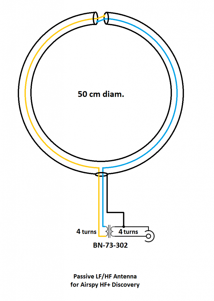
I’m neither an engineer nor am I an antenna expert, so I actually turned to Airspy president and engineer, Youssef Touil, to learn how, exactly, this passive loop works. Youssef was the guy who experimented with several loop designs and ultimately inspired me to build this loop to pair with his HF+ Discovery SDR and the SDRplay RSPdx. “The main characteristic of this loop,” Youssef notes,  “is its ability to cancel the electric noise much better than simpler loop designs.” Got that!  [See loop diagram below]
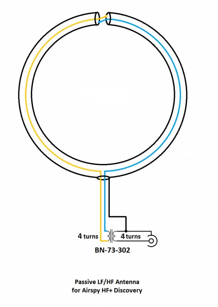
“The second characteristic of this loop antenna is that it is a high impedance loop, which might appear counterintuitive. This means it can work directly with many receivers that have a low noise figure, in order to mitigate the impedance mismatch loss.

Note the resonance lobe near 4MHz. The resonance frequency is controlled by the diameter of the loop, the parasitic capacitance of the cable, and the loading from the transformer. It happens to be located right where we need it the most.

The transformer is basically a 1:1 BALUN that covers the entire HF band with minimal loss. Our BALUN has typically 0.28 dB loss.

[…]By connecting the center of this outer shield to the ground of the transmission line, you effectively cancel all the electric noise. The BALUN is required for balancing the electric noise, not for adapting the impedance.

[…]If you want to boost the performance in VLF, LW and MW, you can try a different impedance ratio, but this will kill the higher bands.”

What makes this loop so appealing (to me) is that it can be built with very few and common parts–indeed, many of us have all of the items in our junk boxes already. As the name implies, it is a passive design, so it requires no power source which is incredibly handy when you’re operating portable.

When paired with a high-dynamic range SDR like the Airspy HF+ Discovery or SDRplay RSPdx, you’ll be pleased with the wide bandwidth of this antenna and noise-cancelling properties.

If you don’t care to build this antenna, Airspy sells their own version of this loop for a modest $35 USD.

But building an antenna is fun and you can tweak the design to customize performance, so let’s get started:

Parts list

  • A length* of coaxial cable for the loop (see notes below regarding length)
  • Another length of cable terminated on one end with a connector of your choice as a feed line
  • A BN-73-302 Wideband 2-hole Ferrite Core
  • Enough coated magnet wire for a total of eight turns on the BN-73-302
  • Heat-shrink tubing or some other means to enclose and secure the cable cross-over point and balun. (You may be able to enclose these connection points with PVC or small electrical box enclosures, for example)
  • Electrical tape

Tools

  • A cable stripper, knife, and/or box-cutter
  • Soldering iron and solder
  • A heat gun (if using heat shrink)
  • Some patience 

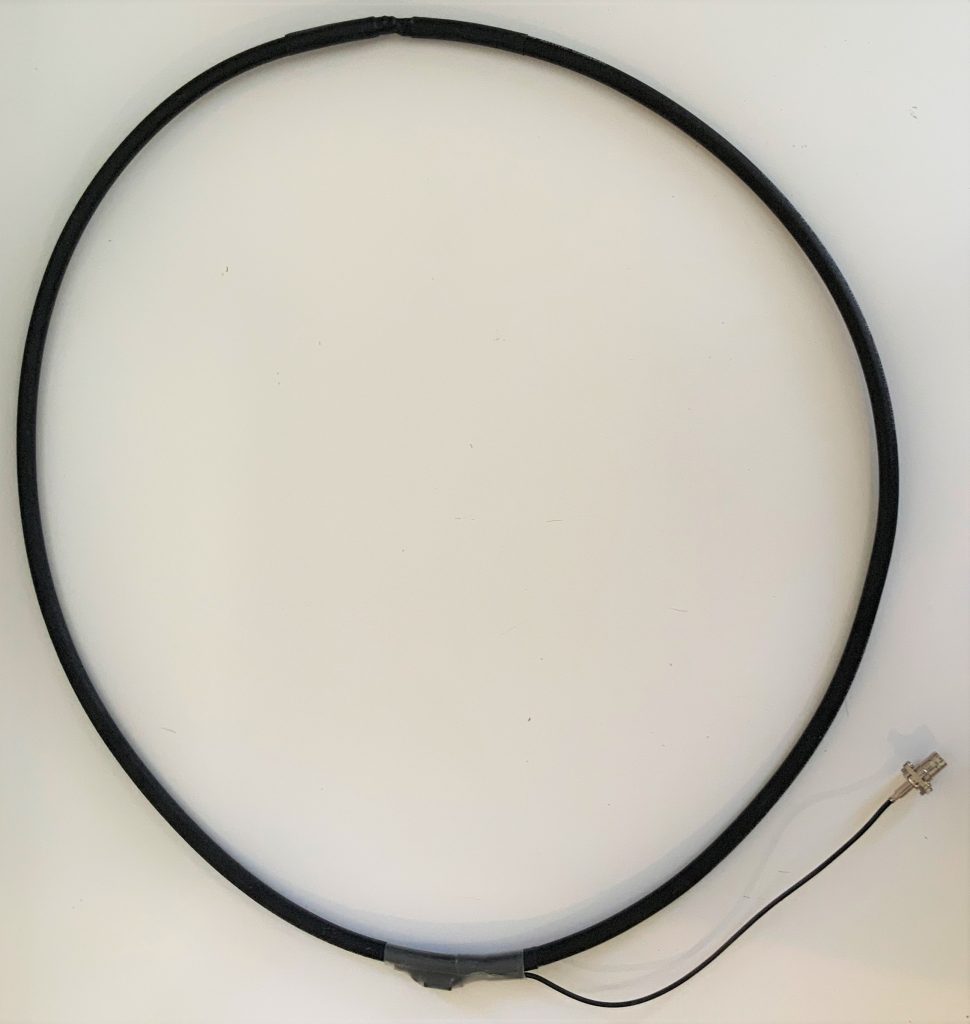
*A note about loop cable length: Vlado and I made a loop with 1.5 meters of cable. The Airspy Youloop ships with two 1 meter legs that combine to give you an overall loop diameter of about 63.6 cm.

Step-by-step guide

When I first decided to build this loop, it was only a day prior to a trip to the South Carolina coast where I planned to do a little DXing. I didn’t have all of the components, so I popped by to see my buddy Valdo (N3CZ). Vlado, fortunately, had all of the components and was eager to help build this loop. As I’ve mentioned in previous posts, Vlado is an amazing engineer and repair technician, so when I say “we” built it, what I really mean is, Vlado did!  But I could’ve done it myself.

This is actually a very simple build––something even a beginner can do, as long as they’re okay with using a soldering iron. It does take patience preparing the loop cable properly. Take your time as you start, and you’ll be on the air in an hour or two.

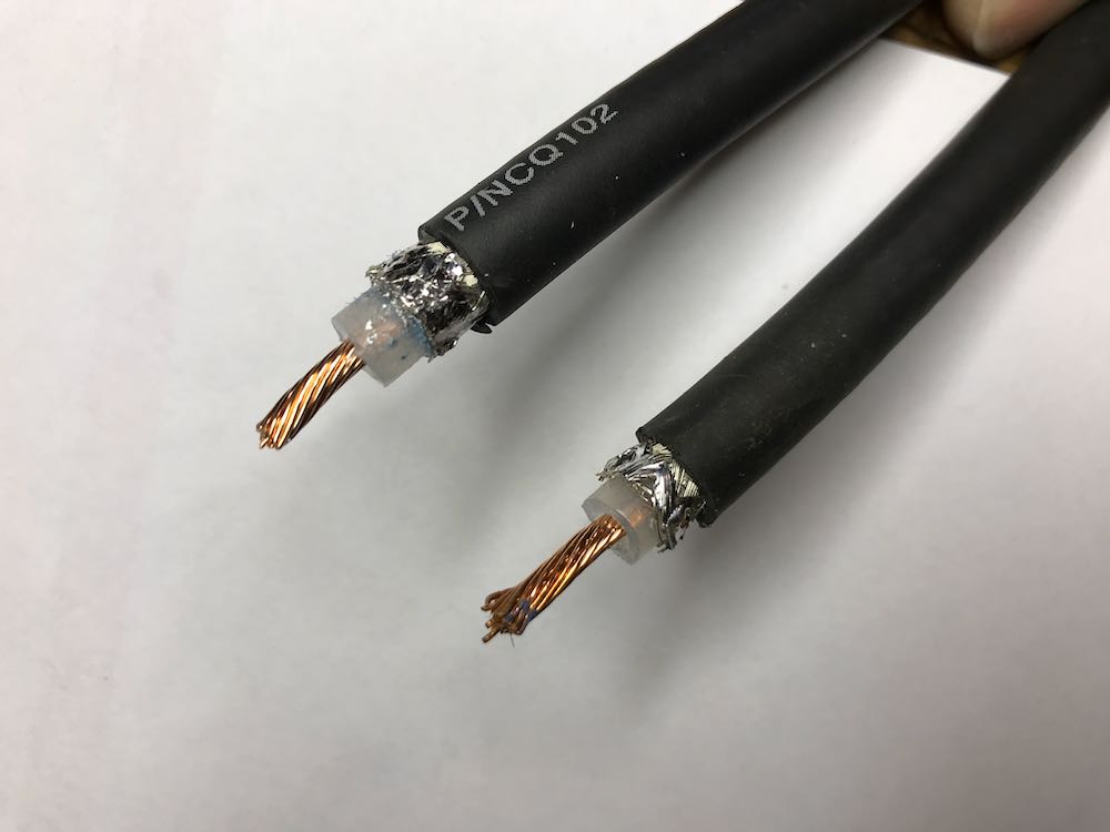
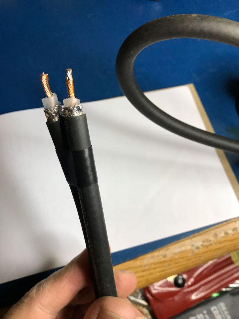
1. Strip the ends of the loop cable.
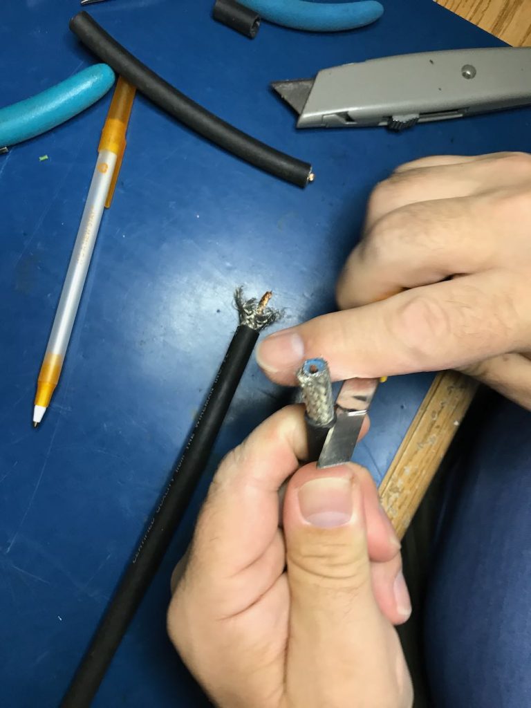
Although your cable type and diameter may vary, strip back the cable ends roughly like this.
To make finding the middle of the cable easier, we taped off the ends.
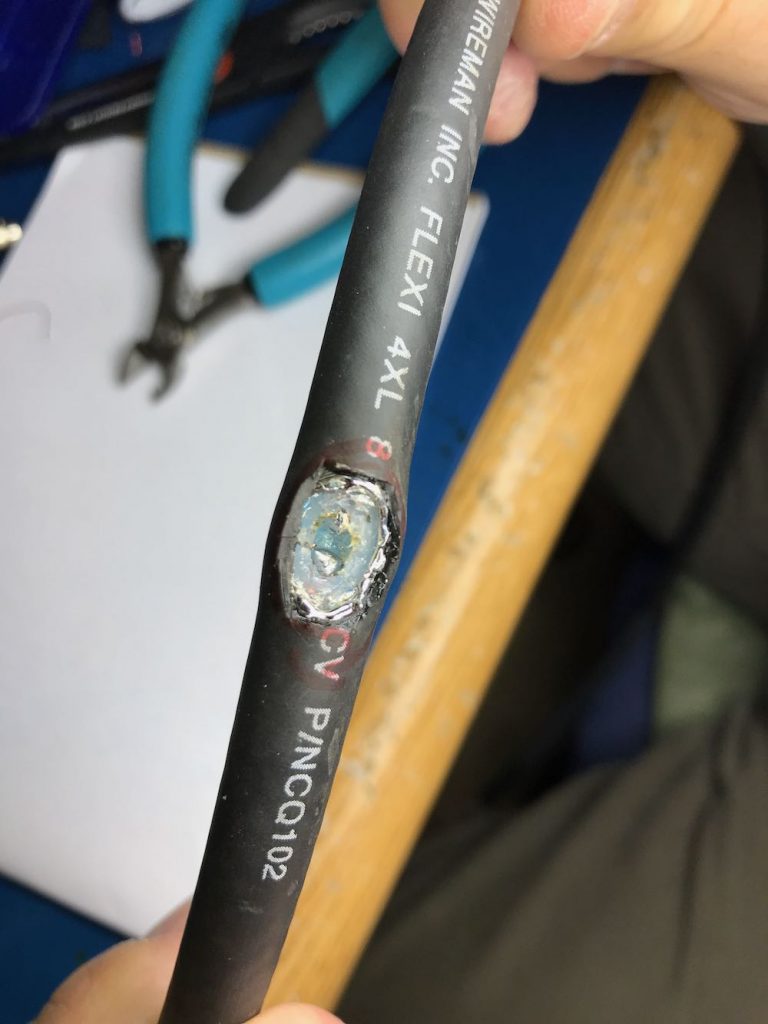
2. Make an opening in the middle of the cable to attach Balun leads to center conductor.

This is the trickiest part of the whole operation. The goal is to create an opening to tap into the center conductor of the cable.

You need to open a hole in the middle of the cable by

1 cutting away a portion of the outer jacket;

2 carefully separating and opening the shielding;

3 digging through the dielectric core, and finally

4 exposing the center conductor of the cable

Try to make an opening just large enough to gain access to the cable’s center conductor, but no bigger. Don’t allow any piece of the shielding to touch the center conductor.

When you reach the center conductor, expose enough of it so that you can clip it in the middle and create an opening to solder your balun leads to both conductor ends.

Once you’ve finished with this step, your cable should look something like this…
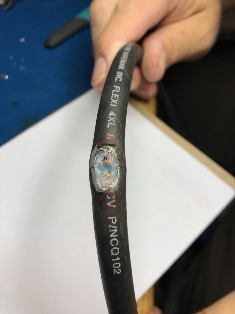
In the photo above, note that the shielding is completely pulled away, the dielectric core has been cut through, and we’ve clipped the center conductor, leaving a gap large enough to solder.

3.  Make a 1:1 Balun

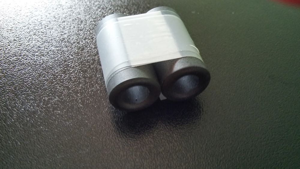
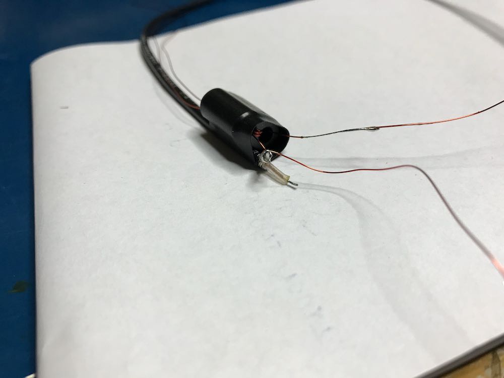
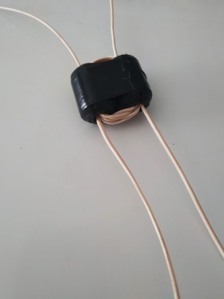
Grab your BN-73-302, and with the coated magnet wire, make four windings on one side, and four on the other. It should look like this:
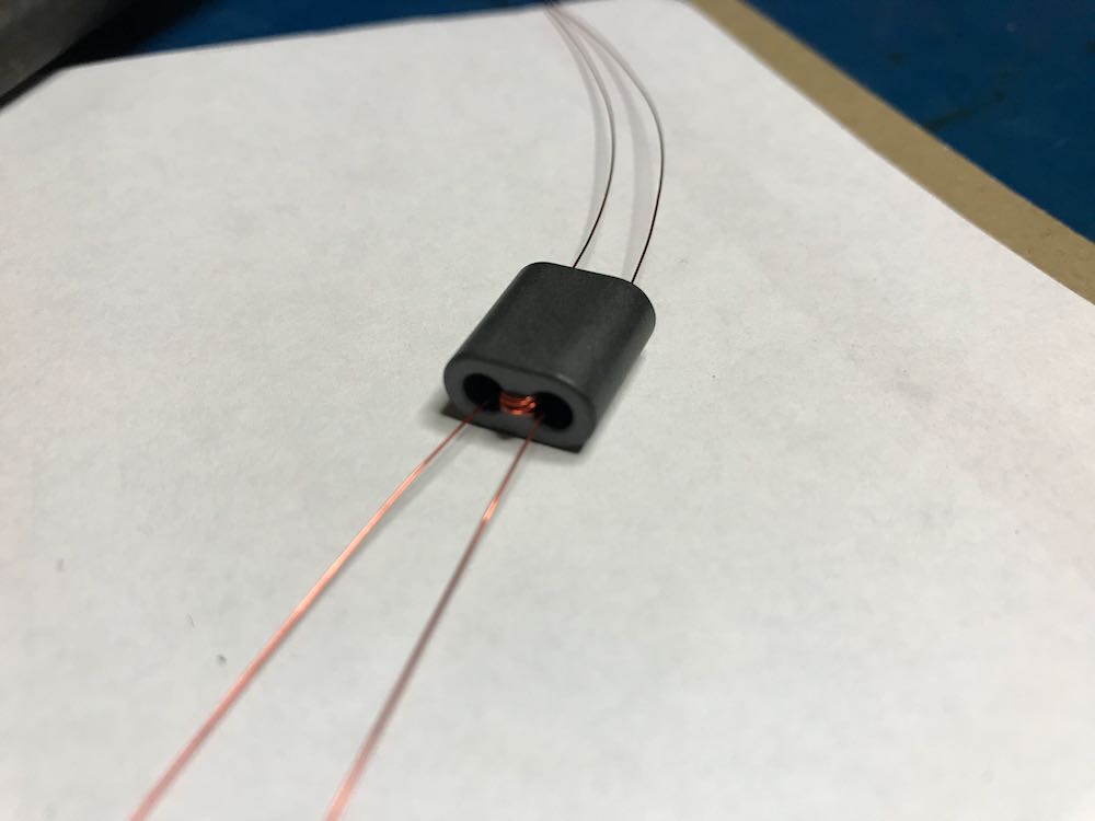
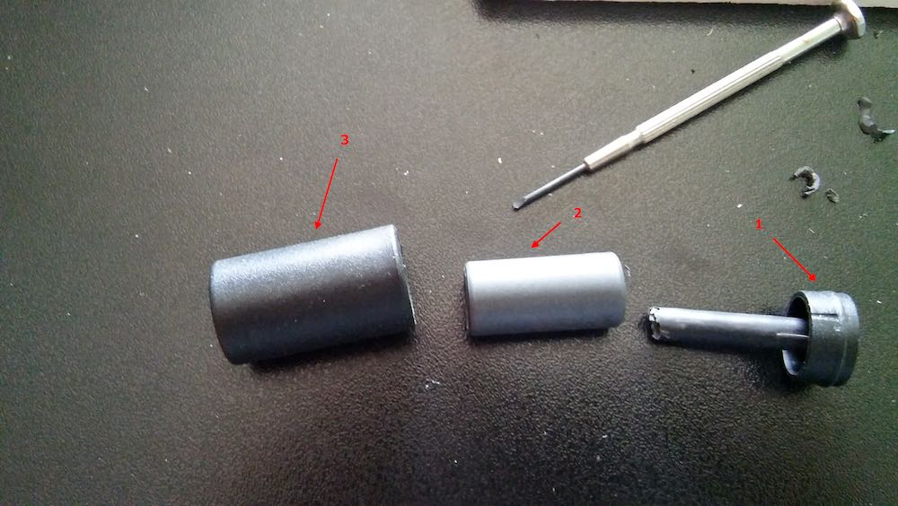
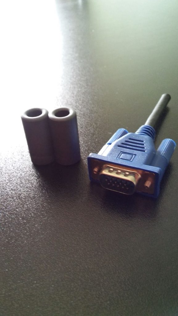
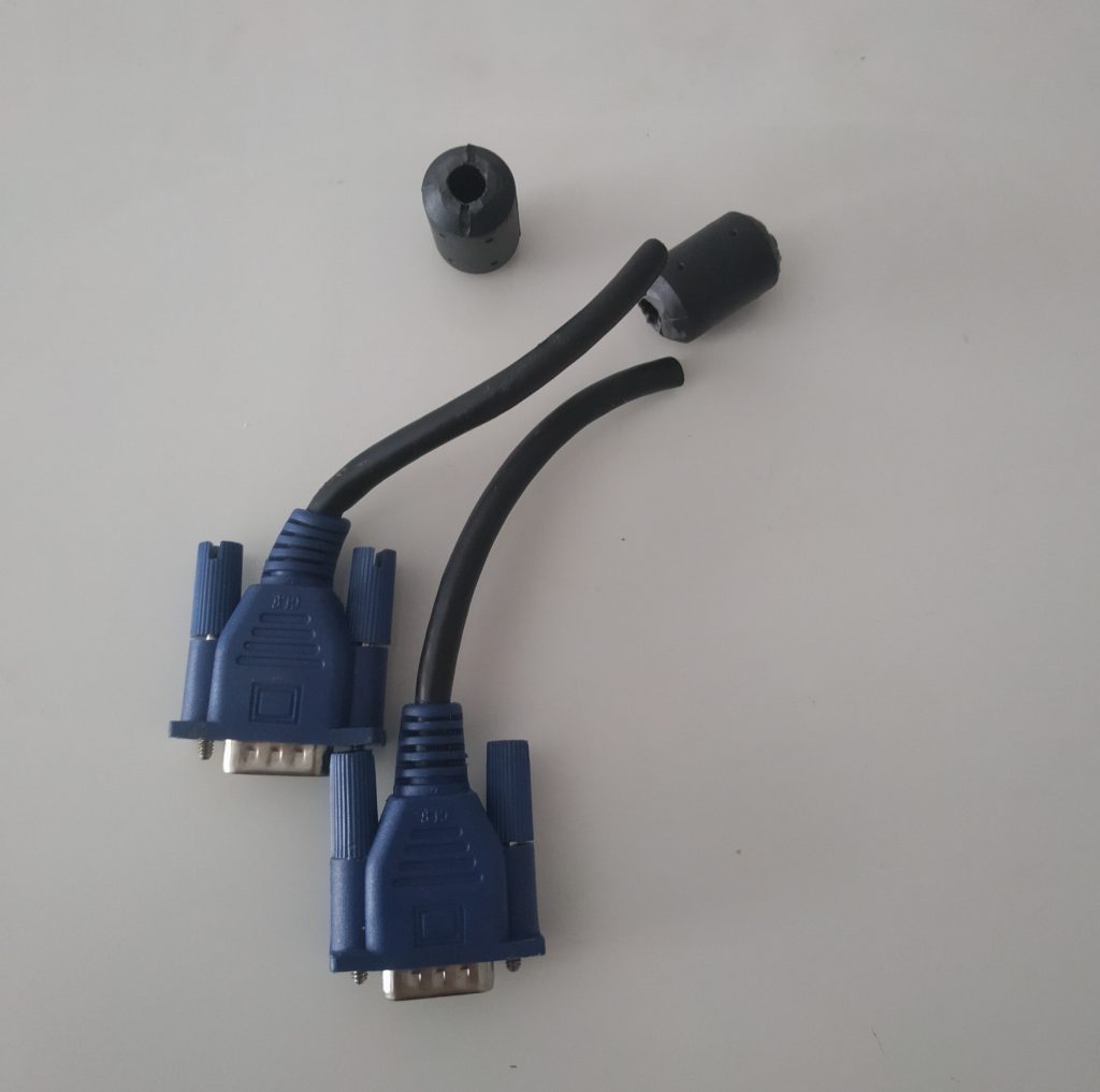
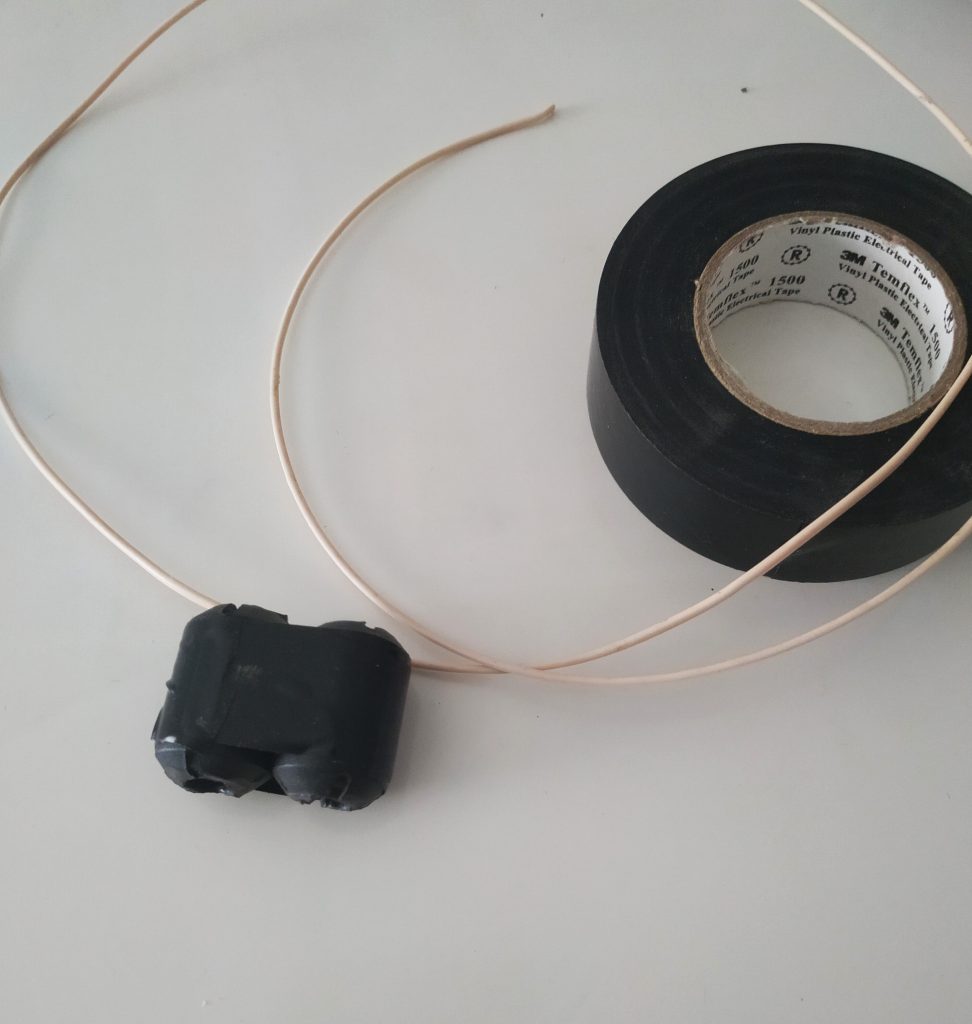
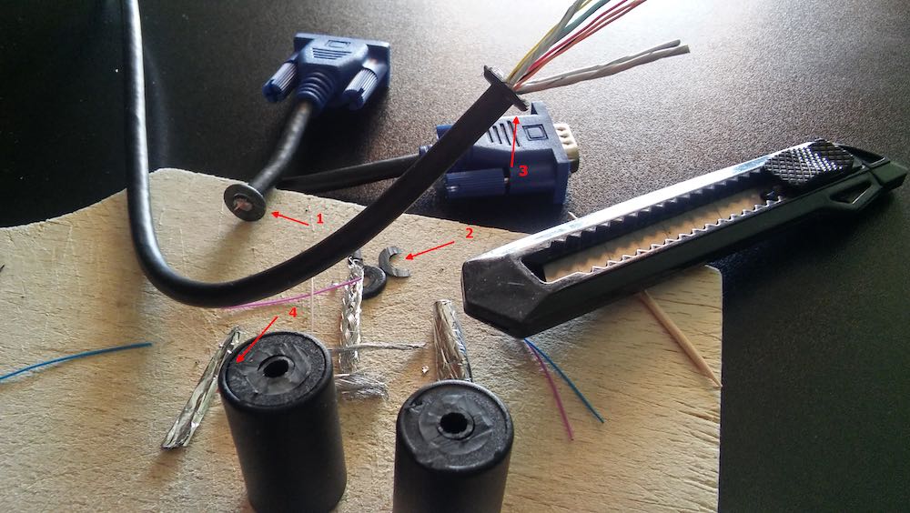
Don’t have a binocular ferrite core like the one above? If you have a broken cable with ferrite cores, you can hack one! Click here to learn more.

4. Connect the Balun to a feed line.

Vlado just happened to have a BNC pigtail in his shack (he’s that kind of guy), so we cut and stripped one end, then connected the center conductor and shield to one side of the balun. We then enclosed the balun in heat shrink tubing to make it a little easier to attach to the loop later:
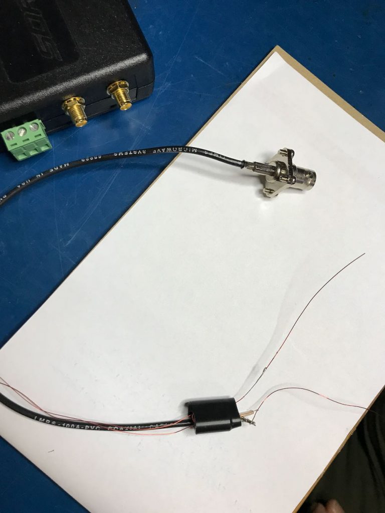
Of course, you could also create this junction in a small enclosure box or short cross-section of PVC. There are a number of ways you could secure this.

Youssef also added the following note about the feedline:

To use the NCPL antenna without a preamp, it is recommended to keep the length of the cable below 10 meters. The supplied Youloop 2 meter cable [for example] is sufficient to keep the antenna away from the magnetic interference of a computer or a tablet, and has very low loss and parasitic capacitance.
5. Connect Balun to the coaxial loop.
To make a solid connection, tin both sides of the center conductor. Next, attach the other end of the balun leads to each portion of the center conductor, as seen below:
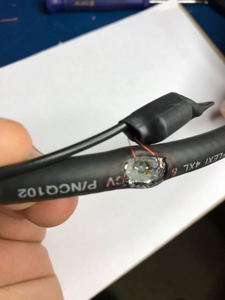
Update: Note in the loop diagram near the top of the page that the ground wire on the output connector connects to the loop coax shielding on the primary side of the balun. I don’t recall that we did this in the build, but I would encourage you to do so. This should result in even lower noise, although admittedly, I’m very impressed with the performance of ours without this connection. Thanks to those of you who pointed out this discrepancy!

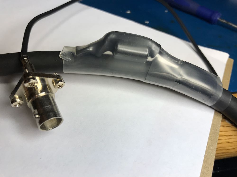
6. Secure the Balun/Coax junction.

Since this loop is intended to be handled quite a lot in the field, make sure the junction point of the balun and coax loop is secure. Again, we used several layers of heat shrink tubing since we had some in the shack.
7. Solder and secure the cross-over point.

Next, create the cross-over point of the loop by simply attaching the center conductor of one end of the cable to the shielding on the other end…and vice versa.

Before you grab the soldering iron, howeverif, like we did, you’re using heat shrink tubing to secure the cross-over point of the loop in the next step, you’ll first need to slide a length of tubing onto the coax before you solder the ends together. Vlado, of course, thought of this in advance…I’m not so certain I would have!
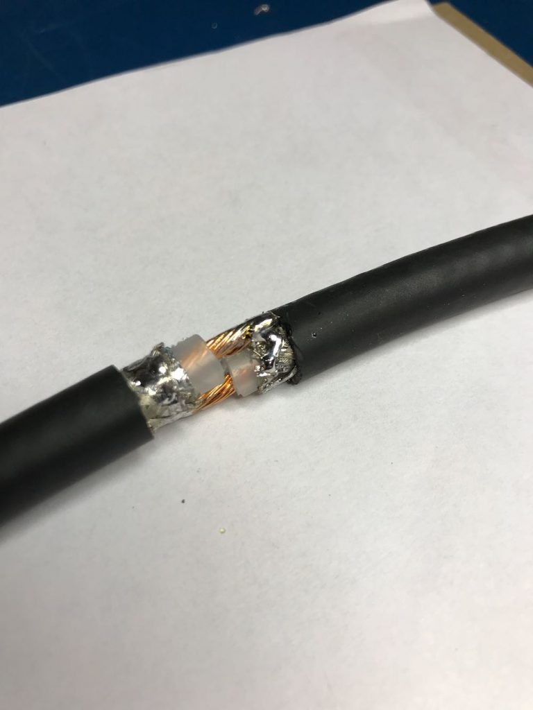
Take your time soldering this connection and making it as solid as you can. If you solder it correctly, and you’re using a high-quality cable as we did, the cross-over point will be surprisingly durable. If you’re using a thinner cable, simply make sure the connection is solid, then use something to make the junction less prone to breaking––for example, consider sealing a length of semi-rigid tubing around this point.
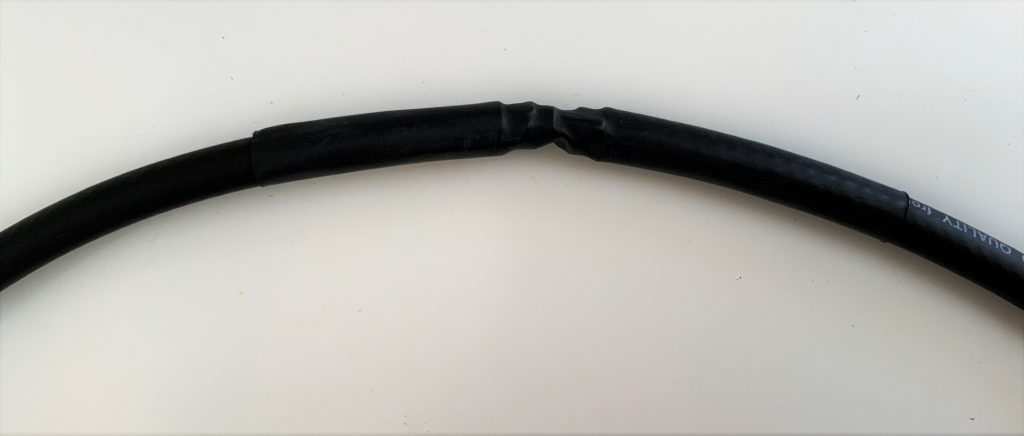
Vlado cleverly added heat shrink tubing around the cross-over point to protect and secure it.

You’re done!

That’s all, folks! Now you’re ready to put your loop on the air.
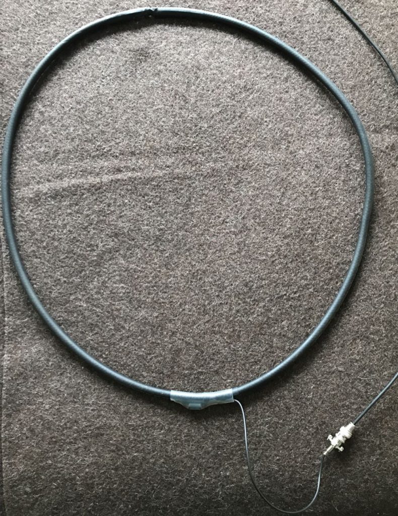
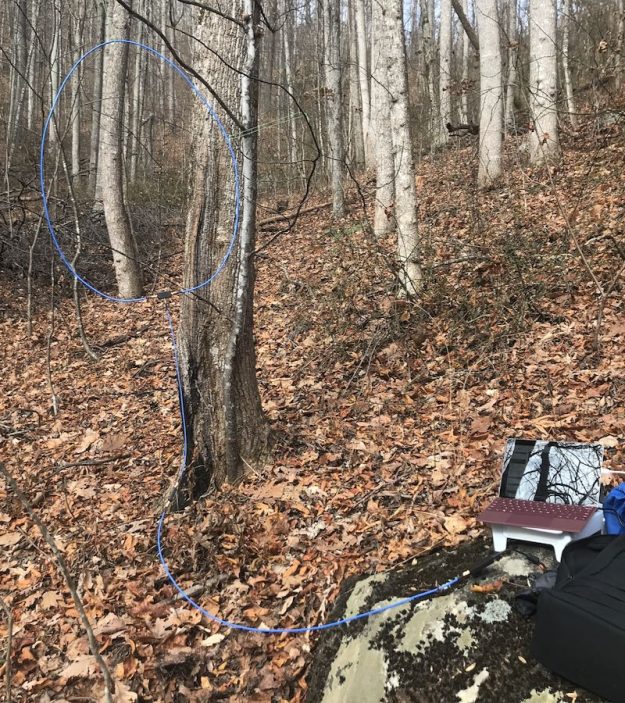
Depending on what type of cable you used for this loop, you might require or prefer some sort of dielectric structure to support the loop so that it maintains the ideal round shape. My loop maintains its integrity pretty well without supports. I’ve supported it a number of times with fishing line/filament from two sides (tying on at 10 and 2 o’clock on the loop). That seems to work rather well.
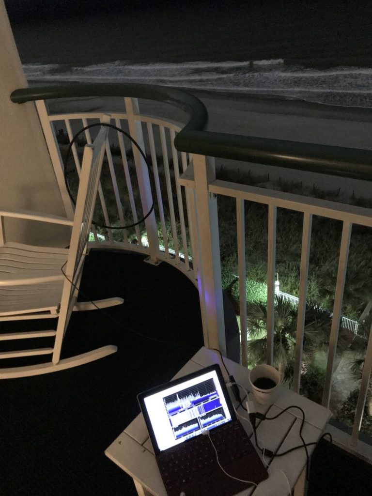
In this setup, I simply used the back of a rocking chair to hold the antenna. As you can see, the loop maintained its shape rather well.

If you’d like to see and hear how this antenna performed on its first outing, check out this post.

Show the Post your loop!

If you build a NCPL antenna, please consider sharing your design here on the SWLing Post! Considering that there are a number of ways this loop can be built, and likely even more optimizations to improve it or make its construction even easier, we’d love to see your designs and/or construction methods. Please comment or, if you prefer, contact me.

And many thanks to my good friend Vlado (N3CZ)  for helping me with this project and allowing me to document the process to share it here on the Post. Got a radio in need? Vlado’s the doctor!


Enjoying the SWLing Post?

Please consider supporting us via Patreon or our Coffee Fund!

Your support makes articles like this one possible. Thank you!

Spread the radio love

Airspy Youloop and Homebrew Passive Loop Antenna designs

Almost two weeks ago, at the 2020 Winter SWL Fest, I gave a presentation called “A New Era in Portable SDR DXing.

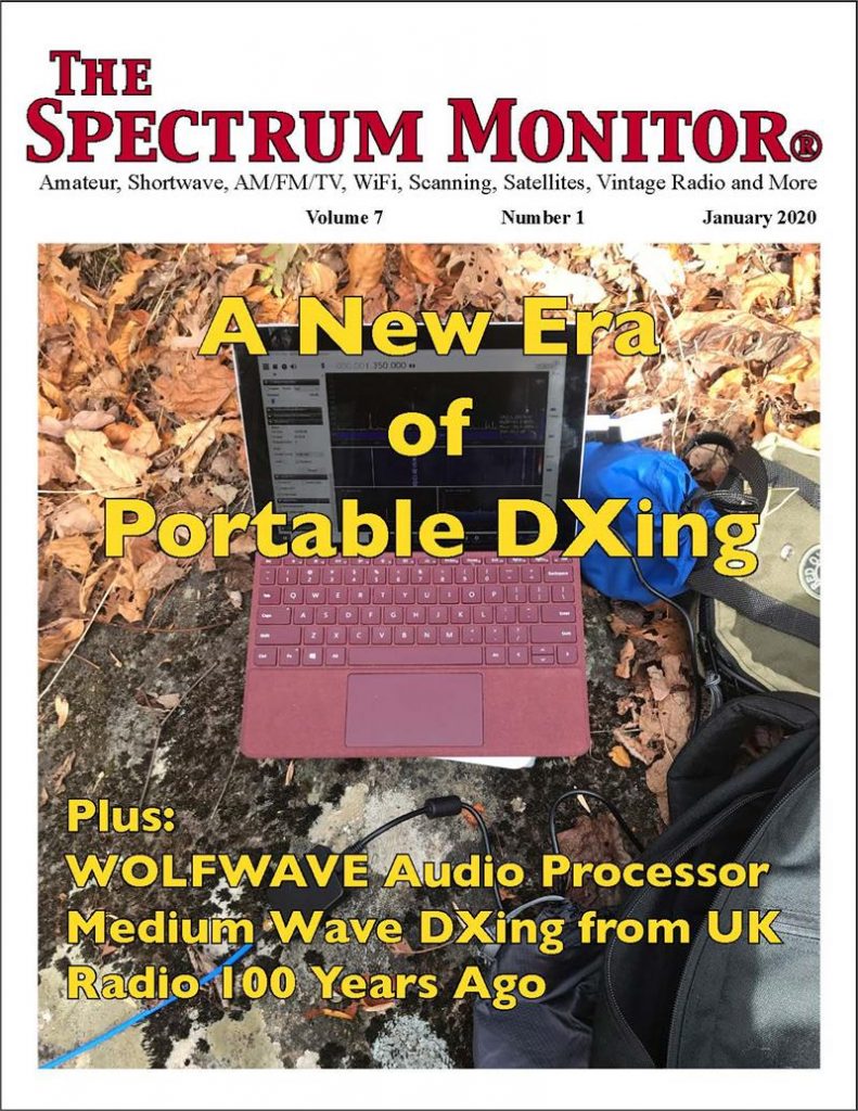
The presentation was essentially an in-depth version of an article I published in the January 2020 issue of The Spectrum Monitor magazine (see cover above).

I devoted a good portion of the presentation describing how to build a passive loop antenna design by Airspy’s engineer and president, Youssef Touil. This passive mag loop takes advantage of the Airspy HF+ Discovery‘s exceptionally high dynamic range and is an impressive performer.

The homebrew loop on the balcony of a hotel.

You may recall, I posted a short article about this loop in November after enjoying a little coastal DXing.

In short? This passive loop antenna pairs beautifully with the Airspy HF+ Discovery. I’ve also been very pleased with results using the new SDRplay RSPdx on the mediumwave band where the receiver now sports a high dynamic range mode.

Overdue corrections…

After returning from the Winter SWL Fest last week, I was hit with an upper respiratory bug. No doubt, a souvenir of my travels!  It wasn’t the flu (I was tested), nor COVID-19, but it did knock me off my feet for a few days with fever, coughing, and headaches. You might have noticed a lot less posts last week and almost no replies from me via email. I’m only now feeling totally human again and trying to catch up with my backlog.

Shortly after my SWL Fest presentation, I realized I made (at least!) two mistakes. I had planned to post corrections here on the SWLing Post last week, but the bug delayed all of that, so here you go:

#1 Schematic of my homebrew passive loop antenna

When Youssef started experimenting with passive loop antenna designs, he posted a few schematics of at least three build options.

Although I described how to build my passive loop antenna, I grabbed the wrong schematic for my presentation slides. Many thanks to those attendees who noticed this.

Here is the schematic I should have shared:

Note that the transformer has four turns on both sides (the one in the presentation had 4:2).

Again, apologies for any confusion.

#2 The Airspy Youloop passive loop antenna

If you’re not inclined to build your own passive loop antenna per the diagram above, Airspy is planning to manufacture and sell a lightweight, high-performance loop of a similar design.

Prototype of the Airspy Youloop in the field (note bright blue cable jacket)

During the presentation, I called the future AirSpy antenna, the “Spytenna.” I was incorrect. (Turns out, I got this name from an early antenna schematic and somehow it stuck in my head!)

Airspy is calling their passive loop antenna the Youloop. Youssef posted the following note in the Airspy email discussion group:

We are currently arranging the shipping of the affordable passive version to Airspy.us and RTLSDR Blog.

Btw, It’s called “Youloop”

Many thanks to Richard Langley and a number of other readers who pointed this out last week.

I’ve had a prototype of the Youloop since November and brought it to the SWL Fest and presentation. It’s a quality antenna and incredibly compact when disassembled and rolled up.

When the Youloop is available to order, we’ll post links here on the SWLing Post.

More to come!

Once I catch up here at SWLing Post HQ, I plan to publish detailed construction photos of the homebrew loop antenna.

Many of you have questions about how to tap into the center conductor at the mid-point of the loop. These photos should help guide you.

Stay tuned!


Do you enjoy the SWLing Post?

Please consider supporting us via Patreon or our Coffee Fund!

Your support makes articles like this one possible. Thank you!

Spread the radio love

KiwiSDR: A brilliant new map portal!

Last month, we noted that the popular SDR.hu KiwiSDR portal now requires registration and an amateur radio callsign to use the site.  While SDR.hu is still online, we certainly get the impression all site development has been halted. This is not the end of the world because SDR.hu is only one of several KiwiSDR portals–we linked to others in our January article.

Personally, I only used the SDR.hu map view to keep track of KiwiSDR sites and found it quite useful because I typically select sites based on geographic location.

A better KiwiSDR map portal

I’ve just learned via the KiwiSDR Twitter account that Priyom.org has updated their KiwiSDR map portal using Dyatlov maps. The results are brilliant and, in my opinion, even better than the SDR.hu’s map.

The Priyom.org map uses the full window, is uncluttered and easier to navigate.

If you click on a KiwiSDR site, you’ll see a pop-up window with basic site information. If you hover the cursor over that site info, another window will pop up with current details about the receiver, number of users, antenna, SNR, and GPS clock (see above).

This is now my favorite way to geographically surf KiwiSDR sites.

Click here to check out the new map portal.


Do you enjoy the SWLing Post?

Please consider supporting us via Patreon or our Coffee Fund!

Your support makes articles like this one possible. Thank you!
Spread the radio love

A Compact RSPdx & Wellbrook Loop Kit for the Beach — My Approach

I have enjoyed three to four medium wave and shortwave DXpeditions per year since 1988, to sites on the Washington and Oregon coasts. I love the chance they give to experiment with antennas in a (hopefully!) noise-free location, and concentrate on catching stations that might not be heard from home.

All of my DX trips have been via car–until now! I’ve just returned from nine vacation days in Hawaii (Waikoloa Beach, on the Big Island), and I thought others might like to see the radio related items I chose to take along for air travel. I’m pleased to report that everything worked as planned, and I have five days of SDR IQ WAV files of the MW band for review, all recorded in the time frame surrounding local dawn.

My goal was not the smallest, most compact portable setup, but one with high performance and modest size. Fitting everything into a day pack was another requirement. A simple wire antenna and an even smaller Windows tablet or laptop than the one I’ve used (and a smaller SDR like the HF+ Discovery, for that matter) would make a much smaller package. However, the items I’ve assembled worked excellently for me during my enjoyable Hawaii vacation. The directional loop antenna provided nulls on medium wave of 30 dB during preliminary tests indoors, a less-than-ideal test situation.

Waikoloa Beach–just one of a zillion picturesque scenes in Hawaii.

Here is a list of what I’ve put together for my DXing “kit”:

    • SDRPlay RSPdx receiver
    • Short USB cable for receiver<>PC connection, with two RFI chokes installed
    • Lenovo X1 tablet— a Windows 10 device with magnetically attached keyboard; this model is a competitor to Microsoft’s Surface Pro tablet
    • Wellbrook Communications’ ALA1530 head amp module, modified for female SO239 connectors enabling use of large diameter LMR-600 coaxial cable as a 2-turn loop element. My antenna setup is similar to Wellbrook’s commercial flexible loop
    • Wooden base for the antenna (ALA1530 is bolted to the base)
    • 20 feet of lightweight RG-174 coax
    • Wellbrook DC interface module for the ALA1530
    • 3.0 Ah LiFePO4 rechargeable battery for the Wellbrook antenna
    • 15 foot long section of high grade “Times Mfg.” LMR-600 coax cable with PL259 connectors (bought from Ebay already assembled/soldered)
    • Fold-up beach mat
    • Small day pack to hold everything

All the contents of this DXing setup fit a standard size day pack.

You’ll note the absence of headphones in the list. This is because my intent from the start was to record all the DX (MW band) as SDR WAV files for DXing post-vacation. That said, I did have headphones in my travel luggage for later spot checks of a few frequencies. That’s how I found 576 kHz Yangon, Myanmar lurking at their 1700 sign-off with national anthem and English announcement. The remainder of the DX to be uncovered will have to wait until I’m back home near Seattle!

The LMR-600 is a very thick and stiff coax cable, whose diameter approaches that used in the standard aluminum tubing ALA1530 series from Wellbrook. It has the benefit of being self-supporting in a 2-turn configuration and will also coil up into an approx. 12-inch package for transport. It just barely fits within the day pack I’m using. As I understand it, magnetic loops with tubing or large coax as the active element, versus simple wire, are more efficient in operation. Whether or not this holds true in practice remains to be seen.

I fashioned a wooden disc 3/4″ thick to attach the ALA1530 head amplifier, as I didn’t want to bring along a tripod or other support stand. The Wellbrook antennas all work well near or at ground level, so I was able to get great reception with the antenna right on the beach. The diameter at two turns of the coax is only a few inches smaller diameter than Wellbrook’s aluminum tubing loops. Three strips of strategically placed Velcro straps help keep the turns together when deployed as well as during storage.

In theory a two-turn loop should give 5 dB less gain than a single turn version; however, my older ALA1530 module has 5 dB more gain than the newer “LN” type, according to Andrew Ikin of Wellbrook Communications. The net result is that my two-turn antenna should have equal gain to the larger one-turn variety. Future experimentation with this DIY coax loop antenna is in order!

The Wellbrook loop antenna, RSPdx receiver, and Windows 10 tablet on the beach in Waikoloa, Hawaii.

Another view of the DXing position. Being this close to the water with my radio gear was unnerving at first, but the wave action on a calm Hawaii beach is totally different from the Oregon/Washington beaches with waves that can move in and out by a hundred feet or more.

The Wellbrook “DIY FlexLoop” works fine at beach level, and is less conspicuous this way, too.

The ALA1530 module is bolted to the 11-inch wooden disc for support. I’ve modified the module’s sockets to securely hold SO239 female connectors.

The commercial Wellbrook FLX1530LN is a fine product, and worthy of your consideration as a compact and high performance travel antenna. Full details can be found at this link.

SDR WAV Files for Download

One of my goals from the start for my Hawaii trip was to bring back SDR “IQ” WAV files for sharing with others. These approx. 900 Mb files cover the entire medium wave band as heard from my beach location in Waikoloa.

The overall page is: https://archive.org/details/@4nradio   Clicking on any of the entries will bring you to a details page. From there just right click on the “WAVE” link, and choose “Save as…” to download. For a few of the recordings I also posted the file that precedes the one that goes across the top-of-the-hour, because things seemed a bit more lively prior to 1700 (which  was at local sunrise, give or take a couple of minutes).

The IQ WAV files are only playable with suitable SDR radio software: SDRuno is first choice (but you need a RSP receiver connected). The files are also is compatible with HDSDR and SDR-Console V3. It may also play on Studio 1 software.

I hope other DXers enjoy the chance to tune through the MW band, as heard from the Big Island of Hawaii.

Guy Atkins is a Sr. Graphic Designer for T-Mobile and lives near Seattle, Washington.  He’s a regular contributor to the SWLing Post.

Spread the radio love

The Malahit-DSP: A potential Holy Grail portable SDR?

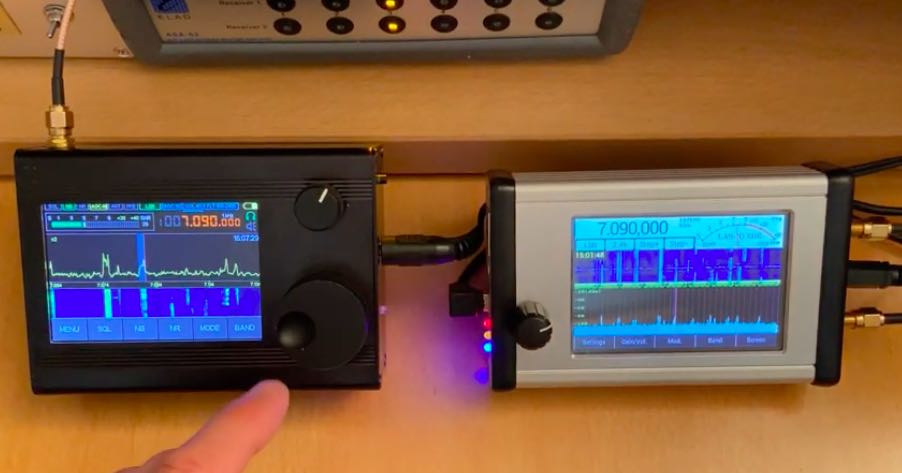
(Image via Fenu Duarte)

Many thanks to SWLing Post contributor, Dan Robinson, who provides this update to his article on the Belka DSP receiver. Dan writes:

One of the other DSP radios shown being demonstrated on YouTube is this one by Georgy Yatsuk, presumably from somewhere in Russia. In his comments posted on January 14th, Fernando Duarte who runs the FENU site says:

“This little gem makes a name for itself. Everyone wants it. But it is still difficult to get. Georgy Yatsuk (RX9CIM) developed this small portable SDR with two of his colleagues. What this little guy offers is simply phenomenal! -Frequency range: 50KHz-2GHz -All important types of operation -160KHz wide waterfall & spectrum display zoomable -Noise reduction adjustable -Noiseblanker adjustable -Equalizer for adjusting the timbre – Controllable via PC -Control via CAT -etc, etc … Because the firmware is still in full development, certain functions will definitely be added. A test and a detailed presentation will be available on my website in the near future. Stay tuned !!”

https://fenuradio.blogspot.com/2020/01/malachit-dsp-der-edelstein-aus-russland.html

As of this moment there is no additional information as to whether this seemingly excellent receiver will ever become available and in what numbers.

Many thanks for this update, Dan! We published a post about the Malahit-DSP in November on a tip from H. Garcia (PU3HAG). I have put in an inquiry to purchase one to evaluate here on the SWLing Post as well.  This does look like a fascinating portable SDR!


Do you enjoy the SWLing Post?

Please consider supporting us via Patreon or our Coffee Fund!

Your support makes articles like this one possible. Thank you!
Spread the radio love

New ELAD FDM-S3 Direct Sampling Wideband Receiver – Specifications and Photos

Many thanks to Paul Jones with ELAD who recently shared the following photos and specifications of the upcoming FDM-S3 SDR:

ELAD FDM-S3 Direct Sampling Wideband Receiver

JAN 2020 SPECIFICATIONS

2 switchable HF Antenna inputs direct sampling

1 VHF Antenna input direct sampling

Works with FDM-SW2 ELAD Software & SDR Console

Optional: Antenna RF input downconversion (50MHz – 2GHz preview)

Real Time I/Q Stream Bandwidth 192kHz, 384kHz, 1536kHz, 12880kHz, 24576kHz

122.88 MSPS – 98.304 MSPS 16bit A/D converter

Clock synchronized to GNSS Global Navigation Satellite System or 10MHz Ext Ref

GNSS works with GPS, GLONASS, GALILEO, BEIDOU

Auxiliary USB used to monitor GPS status or for clock firmware updates

10MHz Clock reference Output

10MHz internal standard TCXO 100ppb referenced, optional 3ppb OCXO referenced

Paul notes that the price will be 949 Euro (roughly $1040 USD). No delivery updates were mentioned.

I’m a bit in awe of the maximum working bandwidth: 24.576 MHz–!

No word on availability yet, but I will post it when ELAD has a firm date. I do plan to review the FDM-S3 once it’s released. Follow updates by bookmarking the following tag: ELAD FDM-S3

Spread the radio love