Many thanks to Joris van Scheindelen (PE1KTH)–an SWLing Post contributor from the Netherlands–for the following guest post:
High Tech AM-FM DSP Receiver From
The old mode AM is still an interesting mode for amateur radio communication, also in amplitude CW.
Building your receiver is not difficult and quite fun. The semiconductor industry makes interesting integrated receiver chips today that will be useful for an AM receiver. Not only for broadcast reception but also for amateur AM reception or as part of an AM transceiver.
Silicon Labs also makes Si4734/35 receivers; these need a CPU to control the receiver, but are of interest for amateur use because the frequency can be tuned in 1 KHz steps and the audio channel bandwidth in 7 steps. There is no need for the transmitter to be on the receiving channel…
Si4835 AM-FM receiver
Looking for a small SW broadcast receiver design, and pocket size, I came to the excellent range of modern DSP receivers in a single chip from Slicon Labs.
I made a test bed set up has been made for the Si4835 AM-FM receiver.
The target specification was:
- minimal components,
- no micro-controller,
- low power,
- backlash free mechanical tuning,
- good sensitivity,
- earphone,
- robust housing,
- a short and small antenna system for outdoor use,
- and minimal controls.
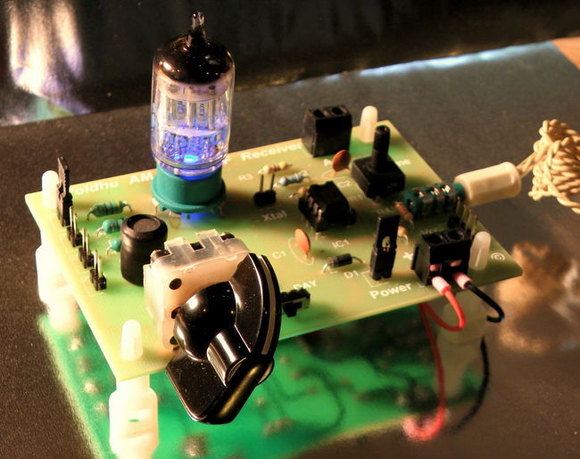
The Si4835 makes miniature design possible on a PCB (see photo Figure 1).
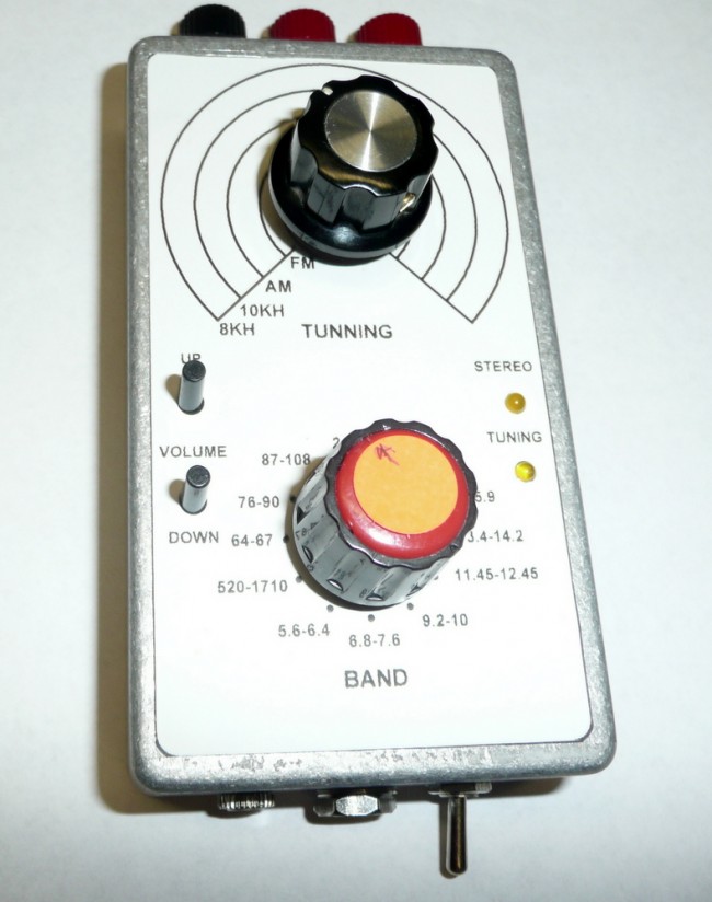
The red Dip (band) switch was replaced by a rotary switch in the final receiver design (Figure 4).
The receiver power is minimal 2 x 1.2 = 2.4 volts or a one cell LI-ION accu.
5 volts is the maximum for the Si4835 chip; current consumption is 30 mA.
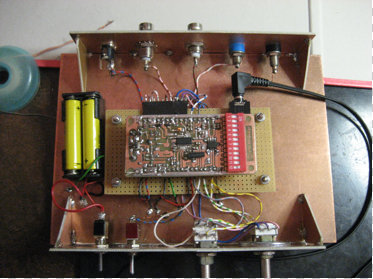
Fig 1. Testbed setup for the Si4835.
The receiver has an RF pre-amplifier transistor and the LF amplifier is the TDA7050T.
All receiver functions are in the chip; the schematic is very simple and can be built with minimal components (see schematic appnote AN555 Fig 2. below).
Only an LF amplifier has to be added to complete the receiver.
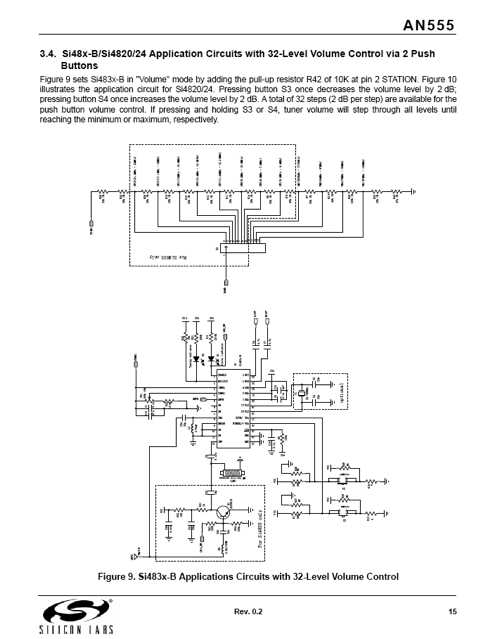
Fig 2. Receiver schematic Si4835 in the AN555 application note.
The Si4835 receiver has the following frequency bands–they are divided in sub bands 800 or 900 KHz wide (See Figure 3). The frequency step tuning is 10 kHz on AM, following the international broadcast raster standard.
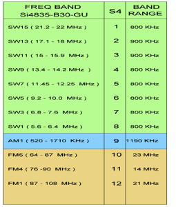
Fig 3. Si4835 receiver sub bands.
This means there are 80 or 90 receive channels in the sub bands and make finding the BC stations on the scale more easy. The 10 KHz scale steps are linear. The frequency stability is locked to the 32 kHz X-tal via the synthesizer so there is no frequency drift. The AM LF audio channel is 5 kHz wide set by the DSP filter. Volume control can be done width 2 up-down push switches or by a LF potentiometer..
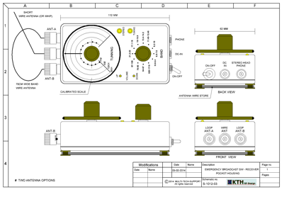
Fig 4. The experimental pocket aluminium receiver housing on PCB2.
Receiving results
I have been testing many hours and I am surprised about this little receiver.
The receiving results are excellent on FM and AM and signals of 2 -3 uV are well received.
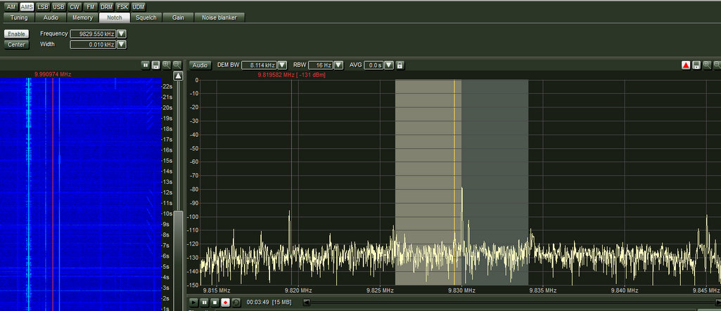
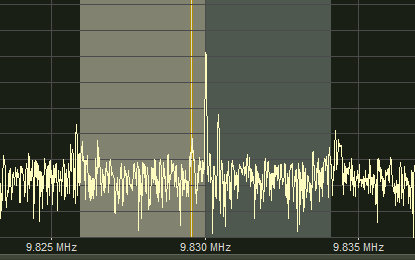
Also the audio quality is good–especially on FM. As can be seen in the frequency table the 40 and 20 meter band are in the range. Clear AM phone amateur transmission has been received when the transmitter was tuned on the 10 kHz raster in 40 meter band on AM.
Also AM modulated CW signals can be received bud not un-modulated carrier CW–they sound “plop…plop”.
The 5 kHz wide LF channel is a bid too wide so many CW signals pass through the audio at the time, but if AM modulated that should not be a serious problem.
The broadcast stations in the SW bands (when the daytime conditions are good) up to 20 MHz are good and strong.
Conclusions
The Si4835 receiver can be a fine broadcast receiver for outdoor work and if an AM transmitter is tuned in the 10 kHz raster this receiver can also used for amateur phone reception.
Addendum: The Si4734/35 is a better amateur AM Receiver
The Si4734 and Si4735 are a better receiver choice for amateur AM purpose because the frequency tuning can be done in 1 kHz steps. Also the BW of the LF channel can be adjusted to 1 kHz wide.
In Fig 5. from the programming APP note you see the code 0X3102 AM CHANNEL_FILTER it is possible to adjust the audio width by sending this code to the Si4734/35.
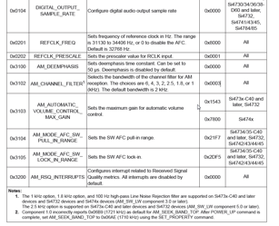
Fig 5. From the programming APP note
The LF bandwidth can be set on 1, 1.8, 2.5, 2, 3, 4 and 6 kHz wide.
This is excellent for modulated CW and AM phone discrimination in the audio channel.
The disadvantage is the need of an CPU and LCD display, “away from a minimalistic design”.
See also the note 1 and 2 improved 100 Hz rejection. See data sheet of the Si4734/35.
It look like that this receiver is a good receiver for building a modern AM-(AM)CW receiver or in a transceiver application. Tuning can be done digitally.
Think about this receiver [and the Si4835 chipset] when you intent to build a high tech AM – T/RX.
73 ‘ Joris van Scheindelen PE1KTH
What a fantastic home-brew receiver, Joris! I love the simple design of your receiver and the fact that it’s quite portable. Thanks so much for sharing your notes and documentation.