Many thanks to SWLing Post contributor, TomL, who shares the following guest post:
My First Loop-On-Ground antenna
A number of people have mentioned the Loop On Ground (LOG) antenna in the past as a good receive-only antenna. I did some research but could only find a few examples by amateur radio operators.
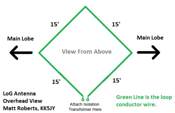
Matt Roberts (KK5JY) has a good article including some antenna theory and measurements, you can find it here:
Someone named Tom (KG3V) has a write up on it but it is a little short on details:
Stana Horzepa (WA1LOU) has something similar:
https://tapr.org/loop-on-ground-log-antenna/
I also read somewhere that for transmitting, a LOG antenna is useless as it radiates much of the energy right into the ground! But I didn’t care about that. I needed something for receive I can deploy easily without supports and take down just as easily. As you may recall, my home condo is literally saturated with noise and I cannot null it out. So a wire looped on the ground is supposed to work? You bet it does!
Of course, there are some conditions to meet. There has to be enough flat ground away from people or pets (or lawn mowers!) who would get tangled in the wire on the ground. The wire should be as close to the ground as possible (although I had good results laying the wire on top of cut grass). The loop of wire can vary in circumference from about 20 feet to 150 feet (the shorter length will stay in an omnidirectional pattern higher in frequency but lower in signal pickup and vice-versa for the longer length). The wire needs to be insulated. That’s about it!
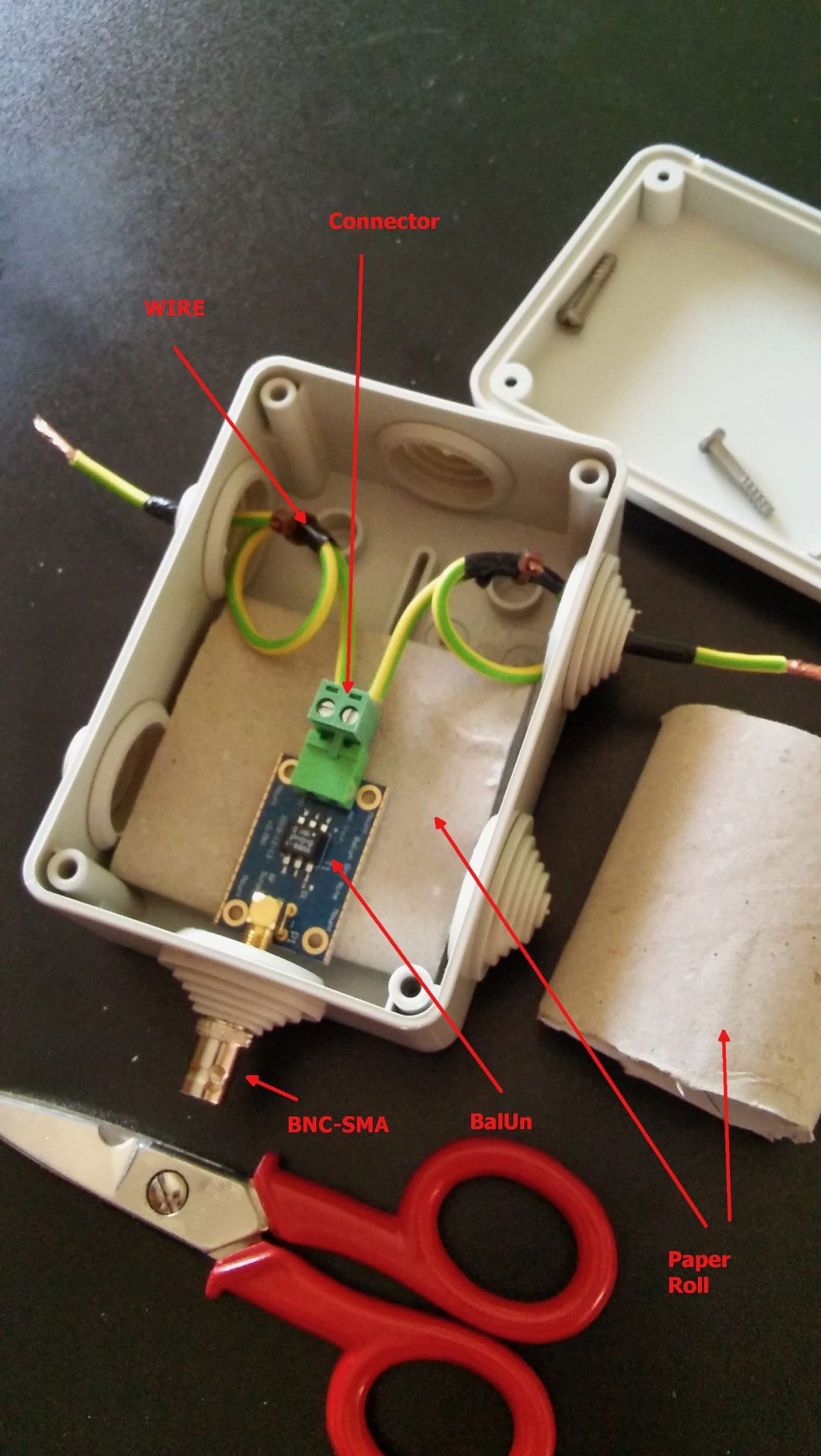
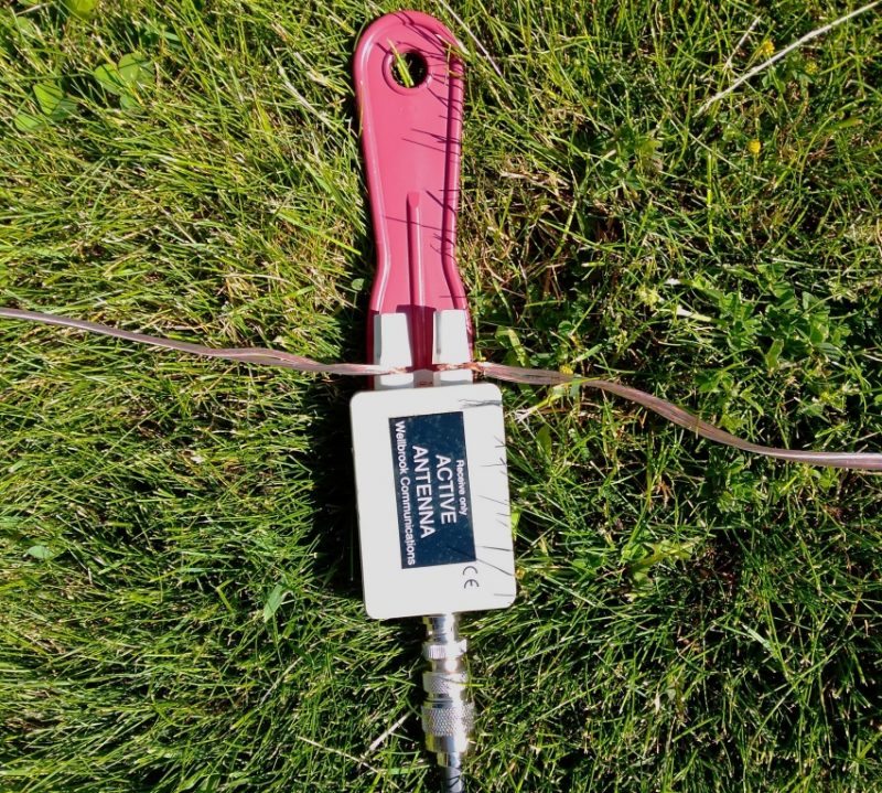
So, off to the hardware store to buy a cheap spool of 100 foot 18 gauge speaker wire. But, the articles mention using a balun and they all made their own. I did not feel like doing that (I am not that good at making things from scratch) and I did not want to spend money ordering one. More reading somewhere informed me that my existing Wellbrook Medium Aperture loop amplifier has a built-in balun at the antenna side of the device. Hallelujah!
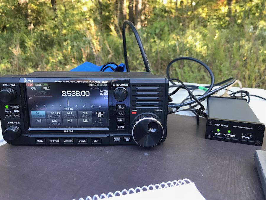
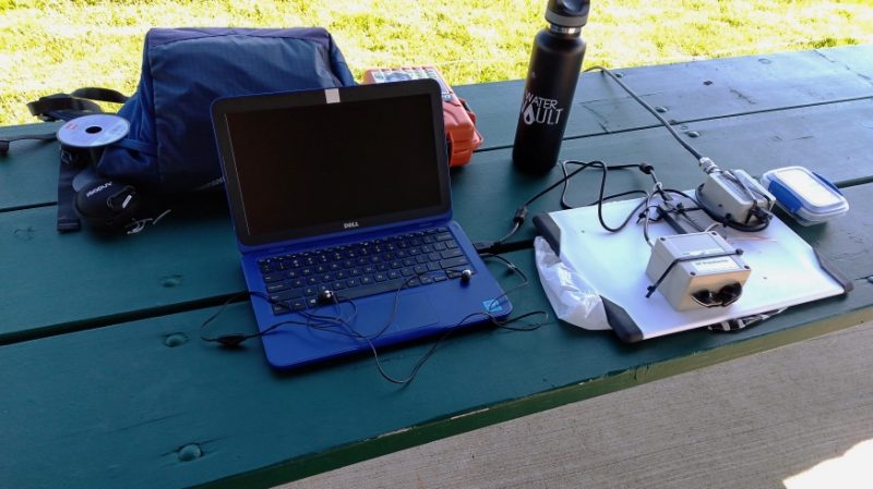
I bundled together the wire, Wellbrook parts and battery supply, small laptop and Airspy HF+ to my favorite Lake Nelson Forest Preserve. The shelter there is little used and is adjacent to the prairie with cut grass. It did take a good 15 minutes to lay out the 100 feet of wire on the ground while trying to keep it as flat as possible. And I did not have enough space for a circle, so I ended up with an oblong shape. The long sides are facing directly north-south, so in theory (I think) this gives me an oblong shaped reception pattern east-west. The photo shows half of the wire laying on the grass.
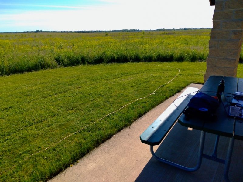
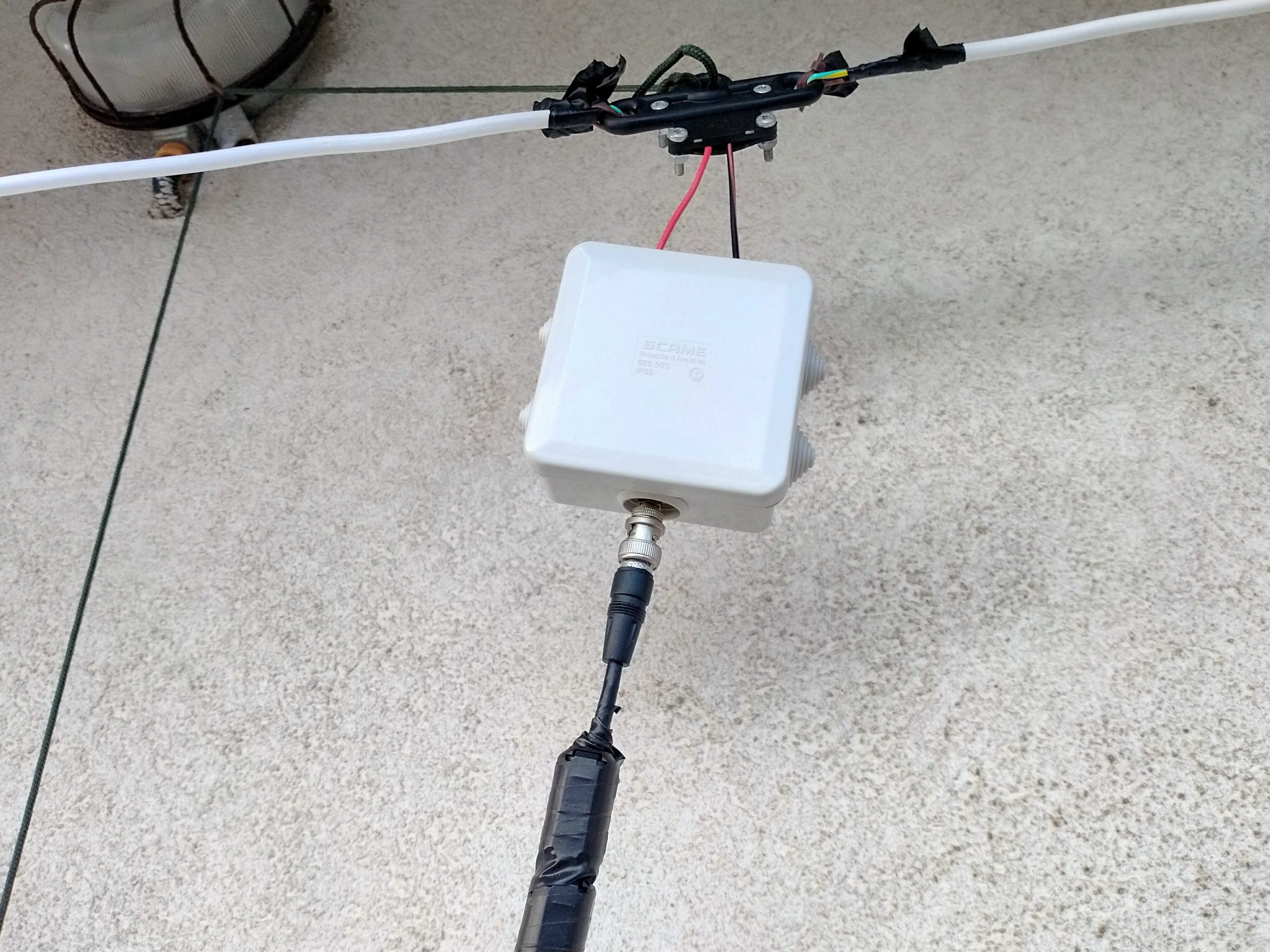
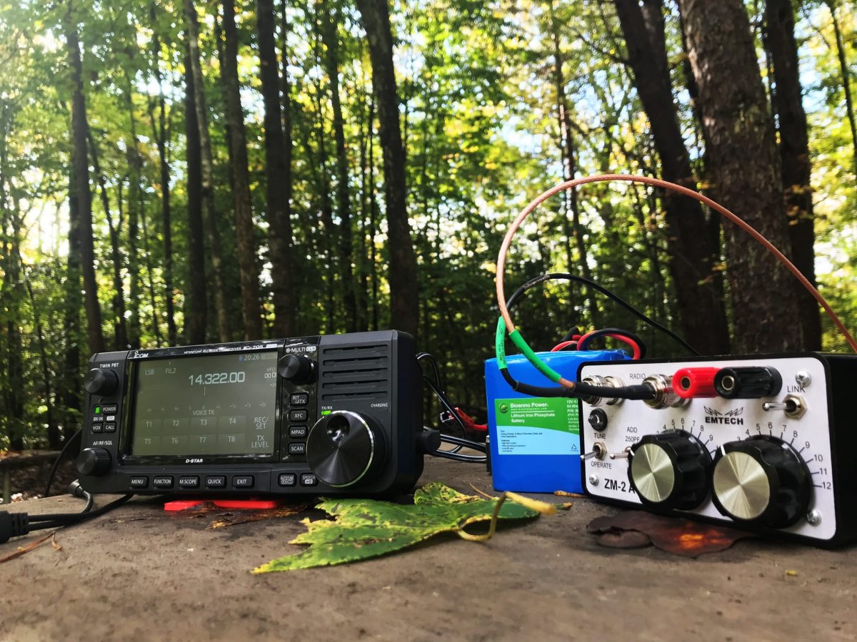
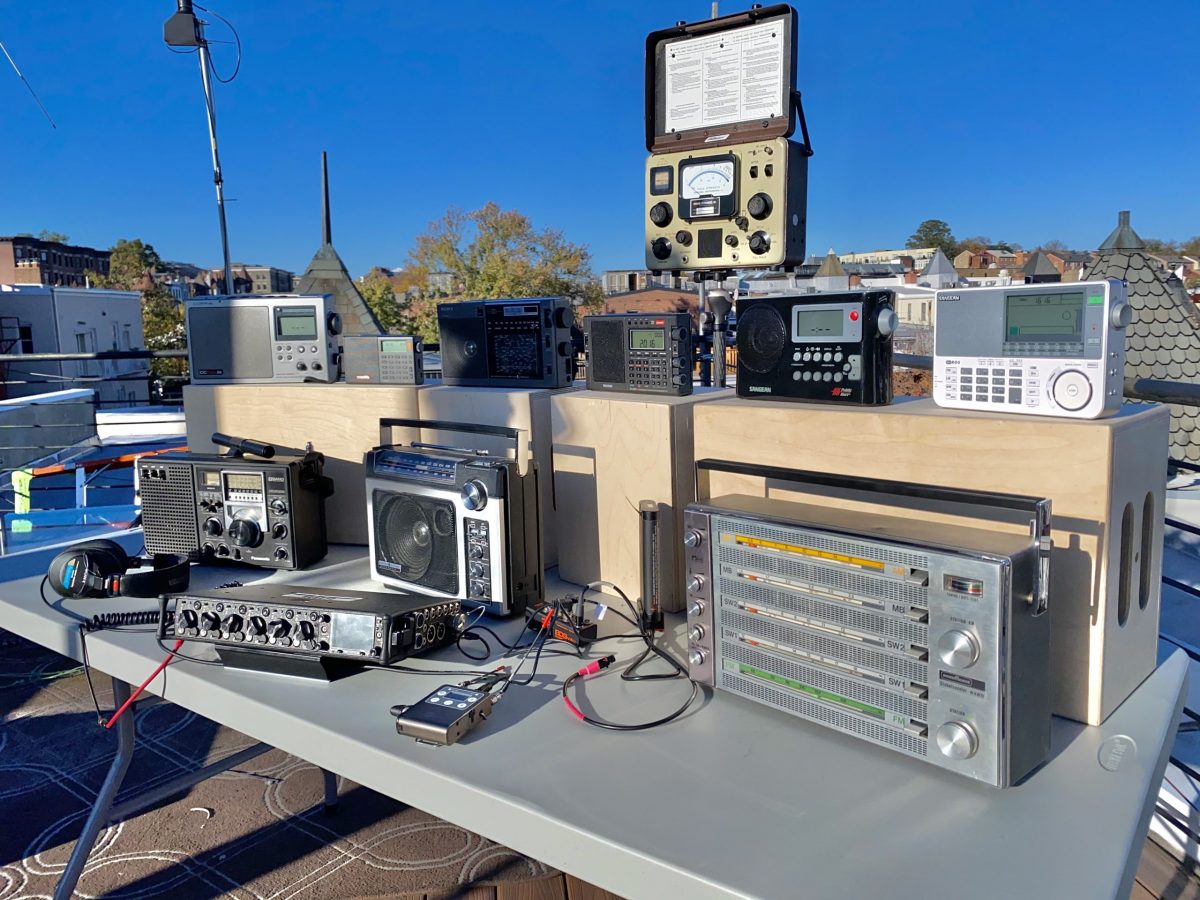
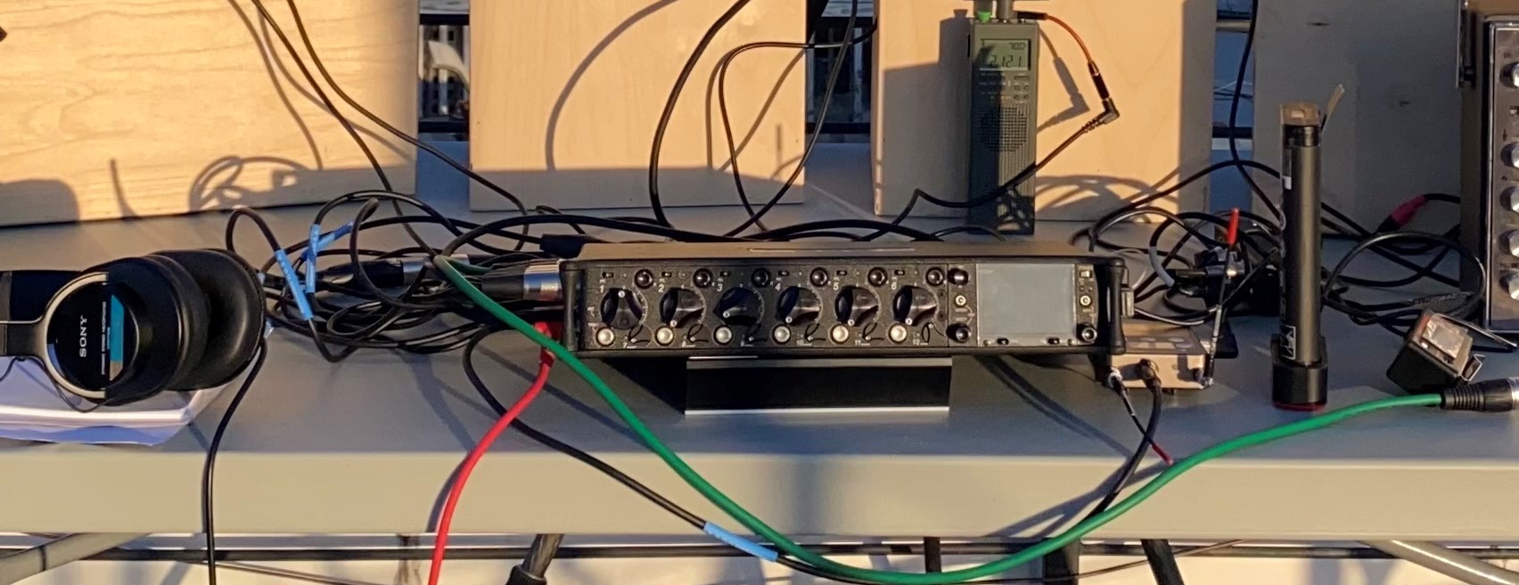
I ended up with this setup on a picnic table at the rear end of the shelter. The coax wire goes from the Wellbrook amp into its power module, then to a Cross Country Wireless preselector, then to the Apirspy HF+ and laptop.
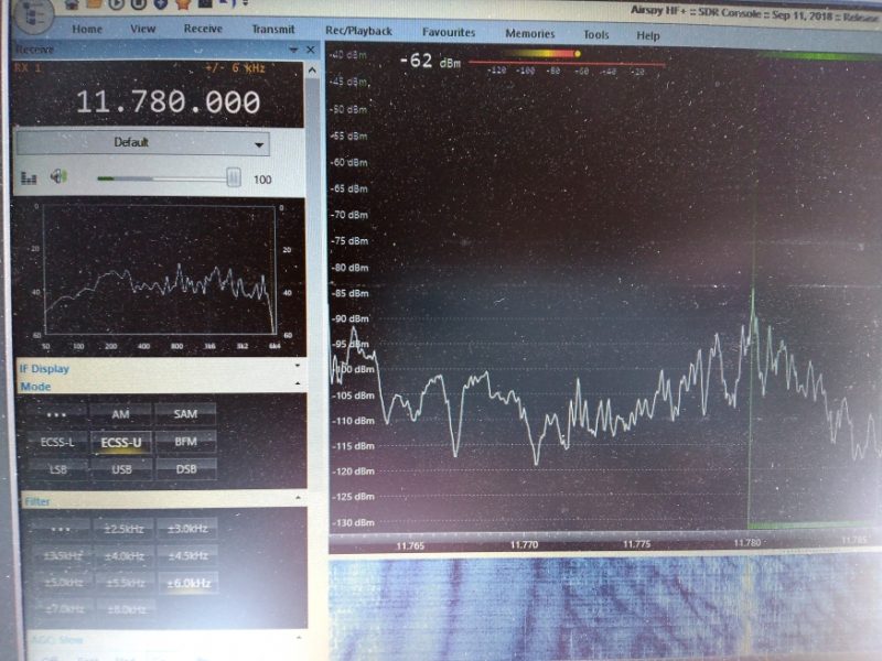
I was really impressed by the signal strength of the usual suspects like Radio Nacional da Amazonia. I could see that the Wellbrook amp was boosting signals across the board with only a little extra noise.
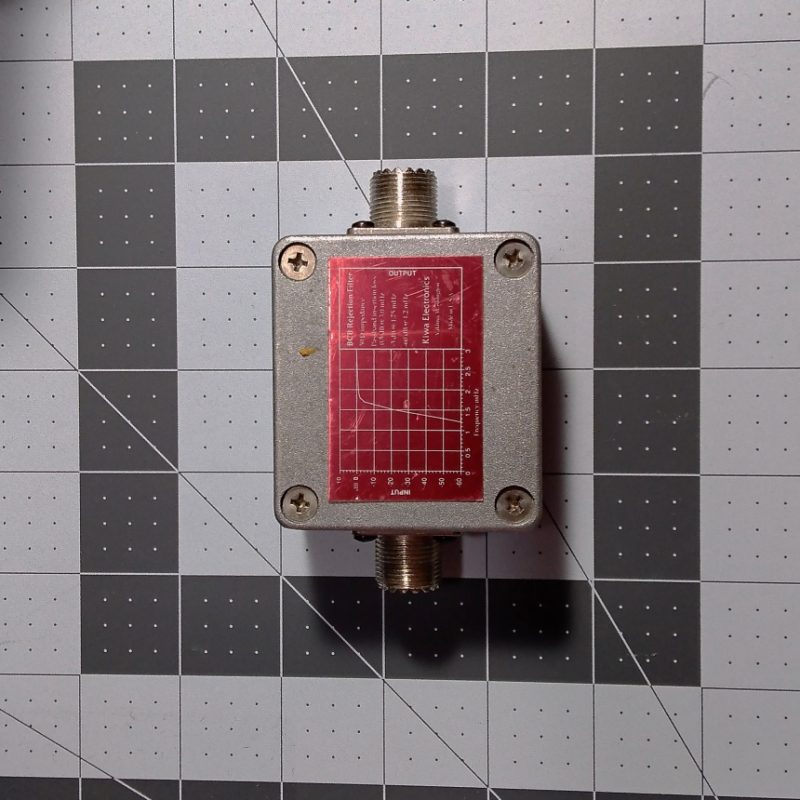
I use the preselector to try to keep the Airspy radio from overloading, especially mediumwave broadcast signals which can sound like a small amount of extra “hash” type noise in the background. I have since added into the accessory chain an old Kiwa Electronics BCB filter that does a great job of knocking down the frequencies below 2 MHz.
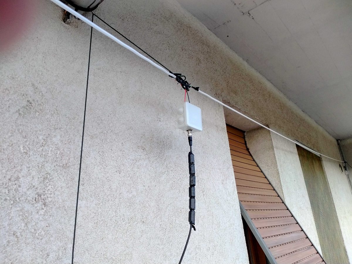
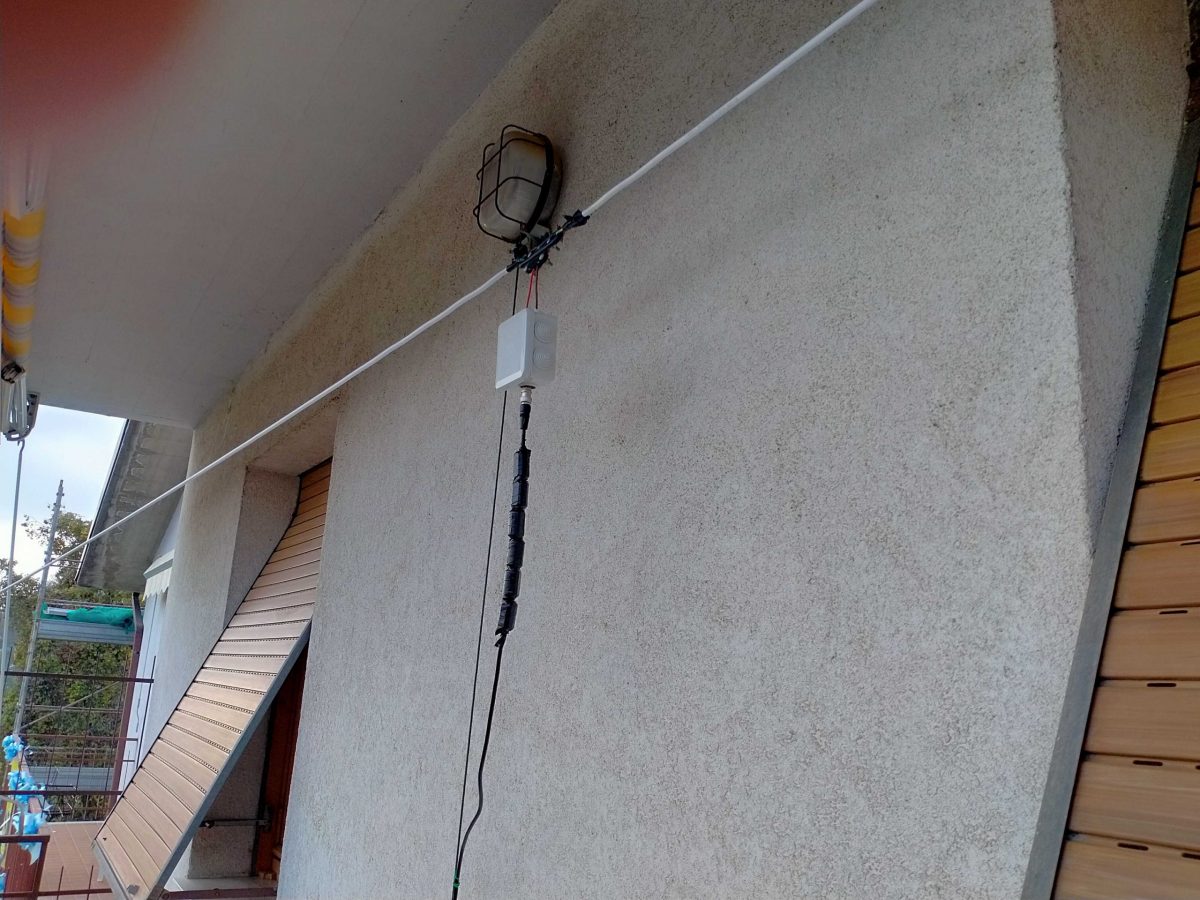
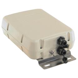
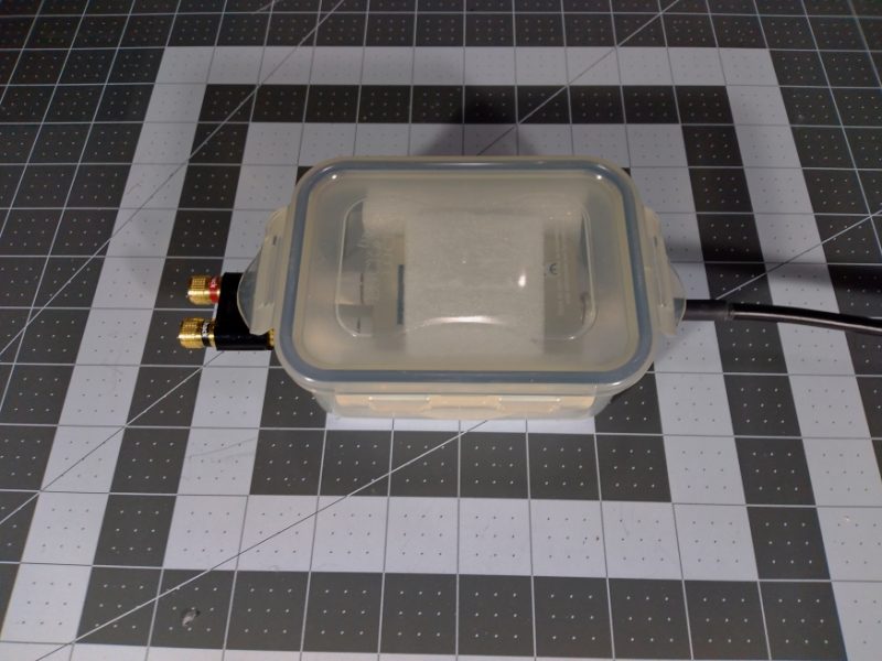
I have also since added a water resistant box to enclose the Wellbrook amp to keep it safe from getting stepped on or too wet.
Also, a couple of weeks later I was able to go to a campgound and try out 60 feet of wire but the result was noisier since I was surrounded by RV vehicles in a crowded campsite. It was not horrible and I was able to listen to some good radio stations but location can matter with any antenna.
I hope you like the recordings below. Because of some serious health issues this summer, these May 31 2020 recordings & report are just being published now (I am recovering slowly but surely!). My small laptop is under-powered, so I was only able to record MP3 files one at a time. It kept me busy as I went from one frequency to the next and kept recording anything I heard. I was able to hear a couple of stations I never heard before and that is a success in my book.
It remains to be seen if this antenna is as good as my 19 foot vertical antenna attached to the top of the car roof, especially low-angle DX signals. Maybe you will have the chance to experiment as well and share your experience, too. Now, will a small loop-on-ground antenna around my car parked late at night at a far corner of the grocery store work OK??? I will have to try it!
Recordings (crank up the volume if it is too weak):
22:00 UTC, Radio Saudi (Arabic) 11915 kHz
22:04 UTC, KDSA Adventist Radio (Indonesian) 11955 kHz
22:14 UTC, KDSA Adventist Radio (English) 12040 kHz
22:20 UTC, Voice of Korea (Japanese) 11865 kHz
22:23 UTC, Yemen Radio (heavily jammed) 11860 kHz
22:35 UTC, Radio Brazil Central (Portuguese) 11815 kHz
22:50 UTC, WWV booming in 10000 kHz
23:11 UTC, UnKnown (might be FEBC) 9795 kHz
23:15 UTC, China Radio Int’l (Spanish teaching Chinese, from Kashi) 9800 kHz
23:17 UTC, China Radio Int’l Business Radio (from Xianyang) 9820 kHz
23:19 UTC, China Radio Int’l (Chinese from Urumqi) 9865 kHz
23:21 UTC, Voice of Korea (Korean) 9875 kHz
23:23 UTC, Maybe Radio Taiwan without jamming from CNR 9900 kHz
23:34 UTC, China Radio Int’l (Chinese from Bamako Mali) 7295 kHz
23:43 UTC, Radio Nacional da Amazonia 6180 kHz (& 11780 kHz around 40 seconds)
23:50 UTC, MAYBE China PBS from Xinjiang in Kazakh (nothing else listed on schedules) 6015 kHz
23:56 UTC, Radio Mali (French announcer humming to music and acting crazy) 5995 kHz
00:07 UTC, Radio Rebelde (Spanish w/clear signal, Bauta, Cuba) 5025 kHz
00:15 UTC, 75 meter Amateur Radio 3913 kHz (LSB)
00:27 UTC, CHU Ottawa 3330 kHz
00:30 UTC, XEPPM Radio Educacion (Spanish Mexico City) 6185 kHz
This is brilliant Tom! Thank you for sharing.
Our antenna guru contributor, Grayhat, has been encouraging me (understatement!) to build a Loop-On-Ground antenna but I haven’t done this yet because, at home, our driveway would interfere with its deployment. That and I have no RFI to speak of in my rural/remote home so my skyloop antenna is tough to beat. But having one available for portable use would make a lot of sense. I’m going to put this on my 2021 project list!
Post Readers: Do you use a LoG antenna at home or in the field? Please comment!