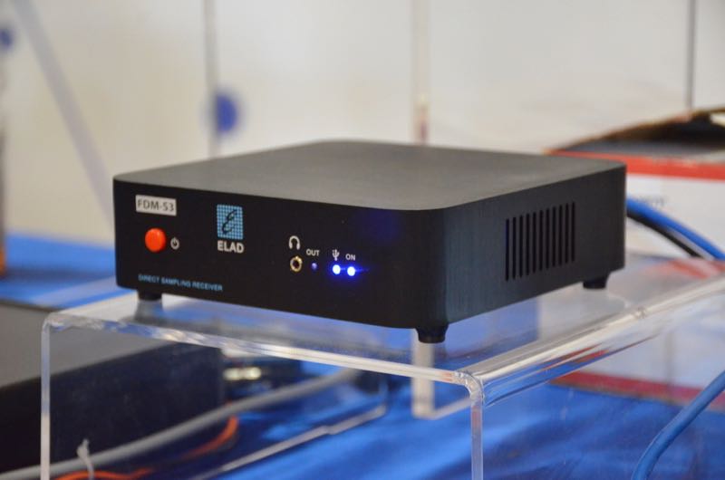
The new ELAD FDM-S3.
The following article originally appeared in the June 2018 issue of The Spectrum Monitor magazine:
SDR Primer Part 1: Introduction to SDRs and SDR applications
I author a radio blog known as the SWLing Post; as a result, I receive radio-related queries from my readers on a daily basis. Among the most common questions are these:
“So, what is an SDR, exactly? Are these better than regular radios?”
and/or,
“I think I’d like to buy an SDR. Which one do you recommend?”
Great questions, both! But, before I address them, I must let the reader know that they are also “loaded” questions: simple enough to ask, but quite nuanced when it comes to the answers.
No worries, though; the following three-part primer sets out to address these questions (and many more) as thoroughly as possible. This first part of the primer will focus on the basic components of an SDR system. In part two, next month, we’ll look at affordable SDRs: those costing less than $200 US. In part three, we’ll take a look at pricier models and even include a few transceivers that are based on embedded SDRs.
But before we begin, let’s start with the most basic question: What is a Software Defined Radio (SDR), exactly?
Not your grandpa’s radio
Here’s how Wikipedia defines SDR:
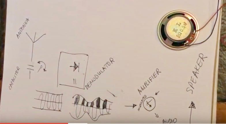
“Software-defined radio (SDR) is a radio communication system where components that have been traditionally implemented in hardware (e.g. mixers, filters, amplifiers, modulators/demodulators, detectors, etc.) are instead implemented by means of software on a personal computer or embedded system.”
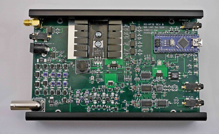
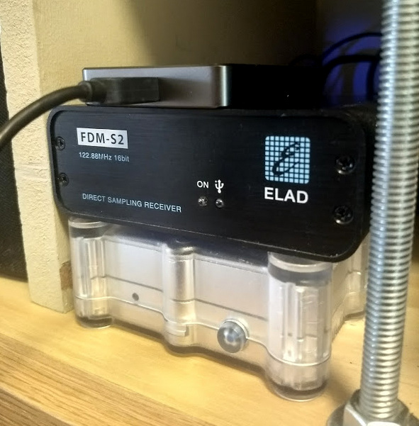
Whereas your grandpa’s radio was all hardware––in the form of filters, mixers, amplifiers, and the like––SDRs are a mix of hardware and software. With the exception of tabletop transceivers and receivers with embedded software and systems (which we’ll discuss in part three of our investigation), SDRs typically take on a “black box” appearance: in other words, the radio looks like a simple piece of hardware with a minimum of an antenna port, a data port and many times there’s also some sort of LED or light to let you know when the unit is in operation. On some models of SDRs, there is a separate power port, additional antenna connections, power switch, and possibly some other features; however, “black box” SDRs often look like a nondescript piece of portable computer hardware––something like an external portable hard drive.
Why would you want an SDR?
Many of us have made it through life thus far without an SDR…so, why in the world should we want the use of one? Below, I’ll list some of the most appealing reasons:
Bang-for-buck
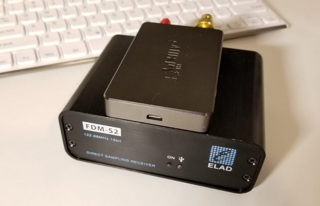
The Airspy HF+ (top) and FDM-S2 (bottom). Photo by Guy Atkins.
By and large, SDRs are quite a value when compared to legacy all-hardware radios. For example, I wouldn’t hesitate to pit my SDRs––such as the $500 Elad FDM-S2 or $900 WinRadio Excalibur––against legacy receivers that cost two to three times their price. Indeed, my $200 AirSpy HF+ SDR will give many DX-grade ham radio general coverage receivers a real run for their money. They’re that good.
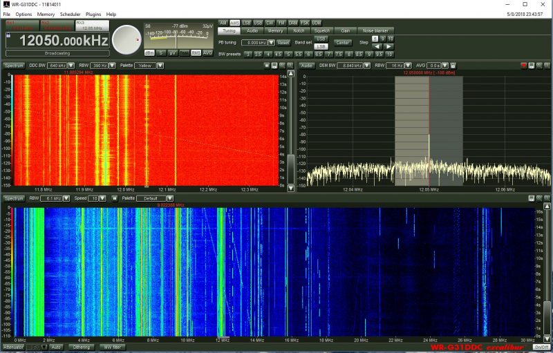
Spectrum display
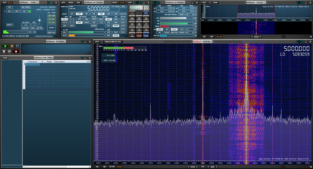
SDR applications have a spectrum display which gives you a real-time view of a broad swath of the radio dial. Whereas you can tune to and listen to one frequency at a time with legacy receivers, SDRs allow you to view, say, the entire 31 meter band. With the spectrum display, you can see when signals come on or go off the air without actually being tuned in to them. You can tell what signal might be causing interference because you can see the outline of its carrier. Spectrum displays are truly a window––a visual representation––of what’s on the radio. Using legacy receivers now often makes me feel like I’m cruising the bands with blinders on. After becoming accustomed to having a spectrum display, there’s simply no way I’d want to be without at least one SDR in my shack.
Powerful tools
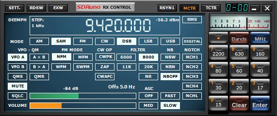
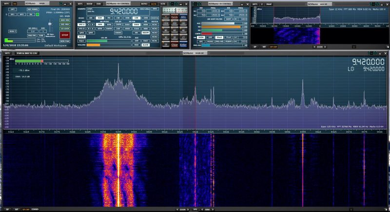
I like how clean the user interface is for this SDR application (SDRuno) window that controls the SDR’s frequency, mode, filters and notch.
SDRs usually afford access to a dizzying array of customizable filters, gain controls, noise blankers, digital signal processing (DSP), audio controls, and more. Being able to customize the SDR’s performance and listening experience is simply unsurpassed. In fact, it’s almost a curse for SDR reviewers like me––comparing two SDRs is problematic because each can be altered so much that identifying the best performance characteristics of one or the other becomes a real challenge. In other words, comparing SDRs is almost like comparing apples to oranges: even using a different application can enhance and thus alter the performance characteristics of an SDR.
Multiple virtual receivers
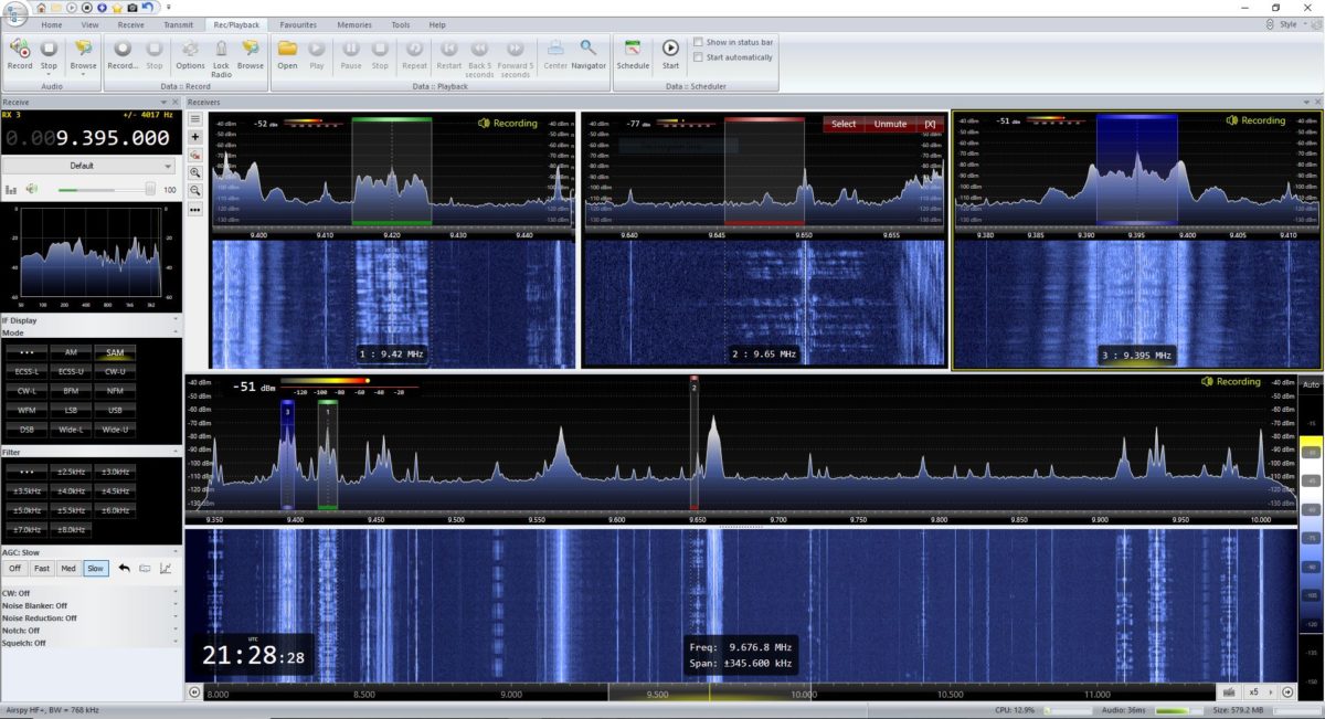
SDR Console makes managing multiple virtual receivers a breeze.
Whereas most legacy tabletop receivers allow you to switch between two VFOs (VFO A and B) some modern SDR applications allow for multiple independent virtual receivers––in essence, multiple sub-receivers. On my WinRadio Excalibur, for example, I can run three fully-functional and independent virtual receivers within a 2 MHz span. On receiver 1, I might be recording a shortwave broadcaster on 7490 kHz. On receiver 2, I might be recording a different broadcaster on 6100 kHz, and following a 40 meter ham radio net on 7200 kHz in the lower sideband.
Recording tools
SDR applications, more often than not, have functionality for making audio recordings of what you receive. Some, like the WinRadio Excalibur and SDR Console, actually allow for multiple simultaneous recordings on all of their virtual receivers.
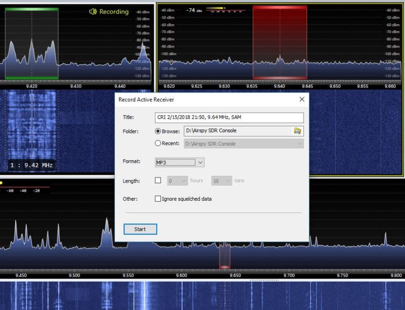
SDR Console recording dialog box
Most SDR applications also allow you to make spectrum recordings, that is, to record not just one individual broadcast from one radio station at a time, but to record an entire broadcast band, all at once. Each recording can easily contain dozens of stations broadcasting simultaneously. Later, you open the recording and play it back through the SDR application. Recordings can be tuned and listened to as if they were live. Indeed, to the SDR application, there is no difference in using an antenna or using a recorded spectrum file; the tuning experience to the listener is also identical.
So imagine that propagation is stellar one evening, or there’s a global pirate radio event just when you’re going to be away from home: simply trigger a spectrum recording and do a little radio time travel tuning later. It’s that easy.
Constant upgrades
Both SDR applications and SDR firmware are upgradable from most manufacturers. In fact, I’ve found that the most affordable SDRs tend to have the most frequent upgrades and updates. Updates can have a positive impact on an SDR’s performance, can add new features, such as the ability to expand the frequency range or more filters or embed time stamps in the spectrum waterfall. It could be pretty much anything and that’s what’s so brilliant. As a user you can make requests; your SDR’s developers might, if they like the idea, be able to implement it.
So, what’s not to love?
Looking at all of these advantages of SDRs over legacy radios, it sounds like SDRs should truly suit everyone. But the reality is, they don’t. For some radio enthusiasts, SDRs do have some unfortunate disadvantages:
First, if you’re primarily a Mac OS or Linux user, and/or prefer one of these platforms, you’ll find you have much less selection in terms of SDRs and applications. While there are a few good applications for each, there are many more SDR applications for PCs operating Windows. Until I moved into the world of SDRs, in fact, I was a Mac OS user outside of work. At the time, there were only one or two SDR applications that ran on the Mac OS––and neither was particularly good. I considered purchasing a copy of Windows for my MacBook, but decided to invest in a tower PC, instead.
Second, one of the great things about legacy radios is that with just a radio, a power source, and an antenna, you’re good to go; travel, field operations, and DXpeditions are quite simple and straightforward. SDRs, on the other hand, require a computer of some sort; when traveling, this is typically a laptop. I’ve spent several summers in an off-grid cabin in Prince Edward Island, Canada. My spot is superb for catching DX, and there’s no RF interference, so I love making spectrum recordings I can listen to later. Problem is, powering so many devices while off-grid is an art. Normally, my laptop can run off of battery power for hours, but when the laptop also provides power to an SDR and portable hard drive, it drains the battery two to three times faster.
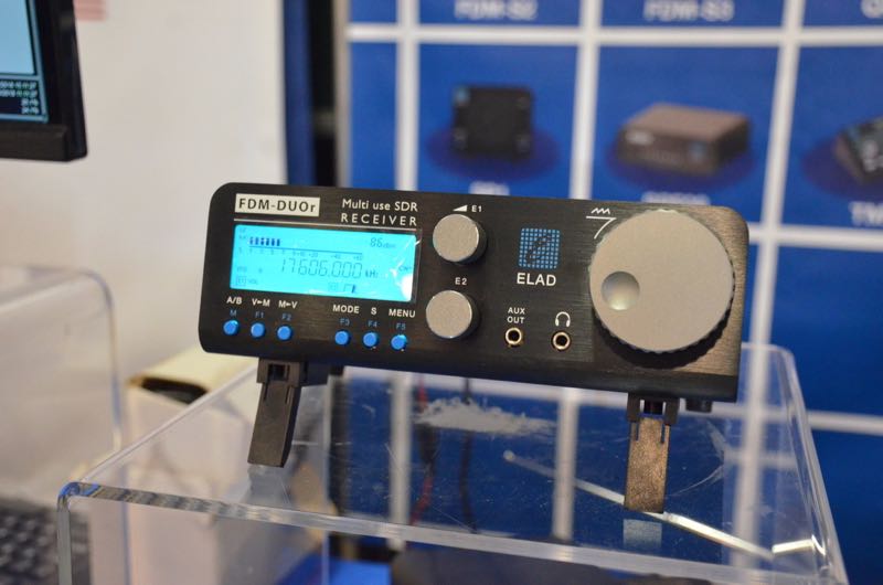
The ELAD FDM-DUOr (receiver).
With this said, keep in mind that there are fully functional tabletop radios (like the Elad FDM-DUO and FDM-DUOr) that are actually SDRs, providing an easy way to bypass this concern.
Finally, there are simply some people who do not care to mix PCs and radio. I’ve a friend who’s a programmer, and when he comes home to play radio and relax, the last thing he wants to do is turn on a computer. I get it––as a former programmer, I used to feel that way myself. But the world of SDRs lured me in…and now I’m a convert.
Scope of this primer series
The world of SDRs is the fastest growing, most dynamic aspect of the radio world. Because of this, I simply can’t include all SDRs currently on the market in this primer. Let’s face it: there are just too many, and it is beyond the scope of this article to try to cover them all. Instead, I’ve curated my list, by no means comprehensive, to include a selection of the most popular and widely-used models.
I’ll be focusing on SDR receivers unless otherwise noted. In Part Three, I’ll call out some popular SDR transceivers. Additionally, I’ll bring my attention to bear on the “black box” variety of SDRs.
This primer is long overdue on my part, so I’ll provide answers to the most frequent questions I receive. But though this primer is in three parts, it barely scratches the surface of the vast world of SDRs.
Thus far we’ve defined an SDR and discussed its advantages and disadvantages.
Now, let’s take a closer look at what you’ll need to build a station around an SDR.
Assembling an SDR station

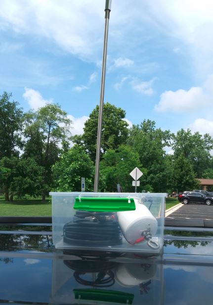
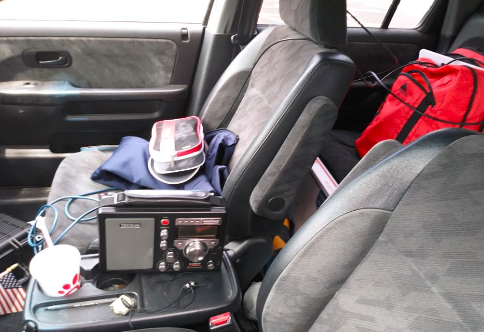
Guy Atkins’ laptop running HDSDR software in his SUV; the receiver is an Elad FDM-S2. (Photo: Guy Atkins)
In truth, most of you reading this primer will already have everything you need to build a listening post around an SDR. Understanding the components of the system in advance, however, will put you in a better position to get on the air quickly with an SDR that suits your needs best. Let’s discuss this component by component.
A computer
By virtue of reading this primer now being displayed on your screen, unless you’ve printed it out, I’m guessing you have access to a computer of some sort.
SDRs are really quite flexible in terms of computer requirements. SDRs are compatible with:
- A desktop PC running the Windows operating system
- A laptop PC running the Windows operating system
- A desktop Apple computer running MacOS and/or Windows
- A laptop Apple computer running MacOS and/or Windows
- A tablet or smartphone computer running Android or Windows
- A Raspberry Pi/Beaglebone (or similar budget computer) running a Linux distribution
If SDRs are compatible with so many computer operating systems and configurations, then why would you worry about which ones to choose?
As I mentioned earlier most, but not all, of the SDR applications on the market are only compatible with the Windows operating system. If you want the most out-of-the-box, plug-and-play SDR options, then you should plan to use a Windows PC. If you’re a MacOS user, fear not. Modern Apple computers can support Windows—you simply purchase a copy of Windows and set your system to boot as a Windows machine (assuming you have the storage space for a dual boot).
Secondly, processing speed is certainly a factor: the faster, the better. While you can use an Android/Windows tablet or a Raspberry Pi to run an SDR, they often don’t have features like multiple virtual receivers, wideband spectrum recording capabilities, and large fluid waterfall displays due to the simple lack of processing power. My guess is that by 2023, however, tablets and budget computers will have ample processing power to handle most, if not all, SDR functions.
Finally, if you plan to make spectrum recordings, especially wideband ones (2 MHz, plus), you need both a snappy processor and a high-capacity hard drive with a decent write speed. This is the reason I now have a desktop PC at home for spectrum recordings: I can use a very affordable SATA drive as a storage device, and the write speed is always more than adequate. My OS and SDR applications run on an SSD (solid state drive) which is very fast. All of my recordings are saved to internal and external 4TB+ hard drives. Happily, I’ve never had a hiccup with this system.
An SDR application
SDRuno has an attractive user interface comprised of multiple adjustable windows.
Wait a minute…am I suggesting you choose an SDR application before you choose an SDR? Why, yes, I am! You cannot use an SDR without an SDR application, but, with only a few exceptions, you certainly can use an SDR application without an SDR attached.
Unlike a legacy hardware radio, you can essentially test drive an SDR by downloading an application (almost always free) and then downloading a test spectrum file. Most SDR manufacturers will have all of this on their download page. Simply install the application, open the spectrum file, et voila! You’re now test driving the SDR. Your experience will be identical to the person who originally made the spectrum recording.
The WinRadio Excalibur application also includes a waterfall display which represents the entire HF band (selectable 30 MHz or 50 MHz in width)
I always suggest test driving an application prior to purchasing an SDR.
While all SDR applications have their own unique layout and menu structure, almost all have the same components, as follows:
- a spectrum display, which gives you real-time information about all of the signals within the SDR’s frequency range;
- a waterfall display, which is a graphical representation of the signals amplitude or strength across the SDR’s frequency range displayed over time;
- filter controls, which help you adjust both audio and signal widths;
- mode selections, which allow you to change between modes such as AM, SSB, FM, and digital;
- a signal meter, which is typically calibrated and resembles a traditional receiver’s “S” meter;
- a frequency display for the active frequency;
- VFOs/virtual receivers, which may have real estate allocated on the display;
- a clock, which displays the time, possibly as both UTC and local time (note that many SDR apps also embed time code in waterfall display);
- memories, where you can store a near-infinite number of frequencies (and some SDR applications allow you to import full-frequency databases); as well as
- other controls, such as squelch, gain, noise blanker, DSP, notch,etc.
After you’ve become comfortable with one SDR application, moving to another can be a little disorienting at first, but the learning curve is fairly short simply because most have the same components.
Types of SDR applications
SDR applications usually fit one of three categories: proprietary app, free third-party apps, paid third-party apps, and web browser based apps. (Assume each application runs on Windows unless otherwise noted.) Let’s take a look at each.
Proprietary SDR applications
Proprietary apps are those that are designed by the SDR manufacturer and provide native plug-and-play support for the SDR you choose. Proprietary apps give priority support to their own SDR, but some are compatible with other SDRs––or can, at least, read spectrum recordings from other SDRs. Most popular SDRs have a proprietary application. Here are examples of a few proprietary apps:
- WinRadio App for the WinRadio/Radixon line of SDRs
- Perseus Software Package for the Microtelecom Perseus
- SDR# App for the AirSpy line of SDRs
- SDRuno App for the SDRplay series of SDRs
- FDM-SW2 App for Elad SDRs
- SpectraVue App for the RFSpace line of SDRs
- SmartSDR App for FlexRadio SDR transceivers
Free third party SDR applications
Free third party applications are incredibly popular and some even offer performance and feature advantages over proprietary applications. Third party apps tend not to be associated with any one particular manufacturer––SDR# being a noted exception––and tend to support multiple SDRs. I’m a firm believer in supporting these SDR developers with an appropriate donation if you enjoy using their applications.
- HDSDR is a very popular application that supports multiple SDRs and spectrum file formats. The layout is simple and operation straightforward.
- SDR Console is a very powerful and popular application. Like HDSDR, it supports multiple popular SDRs. It is my SDR application of choice for making audio and spectrum recordings.
- SDR# runs AirSpy SDRs natively, but also supports a number of other receivers including the venerable RTL-SDR dongle.
- Linrad (Linux)
- SdrDx (MacOS and Windows)
- Gqrx SDR (Linux)
- SDR Touch is a popular SDR application for Android devices (Android)
- iSDR is one of the only SDR applications currently available for iOS devices. Its functionality is somewhat limited. There are other SDR applications in the works, but at the moment these are in development stages only. (iOS)
Paid third-party apps
Paid third-party apps represent a tiny fraction of the SDR applications available on the market. Indeed, at time of posting, the only one I know about that’s currently on the market is Studio 1, which has been the choice for those looking for an alternative application to the Microtelecom Perseus Software Package.
Web browser-based SDR applications
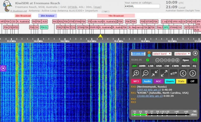
The KiwiSDR browser-based application
This is, perhaps, one of the newest forms of SDR applications. While a number of SDR applications (like SDR#, SDR Console and the Perseus Software package) allow for remote control of the SDR via the Internet, there are actually few applications that are purely web browser-based. At the time of this writing, the only one with which I’m familiar is the KiwiSDR application, which allows both the SDR owner and (if set up to do so) anyone else in the world to operate the SDR as if they are at the SDR’s location. In fact, the KiwiSDR only has a web browser-based application, there is no downloadable application. It will allow up to four simultaneous users, and the experience of using a KiwiSDR locally or globally is nearly identical. If you would like to use a KiwiSDR, simply visit http://SDR.hu or https://sdr.hu/map and choose a remote location.
[Note that if you like web-based SDRs, I highly recommend checking out the University Twente WebSDR located in the Netherlands.]
Choosing an SDR
In Parts Two and Three of this primer, we’ll take a closer look at some of the SDRs currently on the market; prices range anywhere from $15 to $6,000. As you can imagine from such a price range, these are not all created equally.
But first, ask yourself what your goal is with your SDR. Do you want to monitor ham radio traffic? How about aviation communications? Follow pirate radio? Listen to a range of broadcasters? Pursue radio astronomy? Is your dream to set up a remote receiver?
Whatever your flavor of radio, you’ll want to keep some of these needs in mind as you explore the SDR options available to you.
Budget

Be honest with yourself: how much are you willing to spend on an SDR? While entry-level SDRs can be found for anywhere from $15-50 US, a big leap in performance happens around the $100 mark. If you’re looking for benchmark performance, you may need to appropriate $500 or more. Whatever you choose, keep in mind that SDRs are only as good as the antennas you hook up to them. Set aside some of your budget to purchase––or build––an antenna.
Compatible applications
As mentioned above, not all SDRs are compatible with anything beyond the OEM/proprietary application. If you have a choice third-party application in mind, make sure the SDR you choose is compatible with it.
Frequency range
If you want an SDR that covers everything from VLF/longwave up to the microwave frequencies, then you’ll need to seek a wideband SDR. Each SDR manufacturer lists the frequency ranges in their specifications sheet. It’s typically one of the top items listed. Modern wideband SDRs can be pretty phenomenal, but if you never plan to listen to anything above 30 or 50 MHz, for example, then I would advise investing in an SDR that puts an emphasis on HF performance. Check both specifications and user reviews that specifically address performance on the frequencies where you plan to spend the bulk of your time.
Recording and processing bandwidth
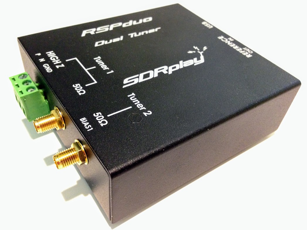
The new SDRplay RSPduo can display up to 10MHz visible bandwidth (single tuner mode) or 2 slices of 2MHz spectrum (dual tuner mode)
If you plan to make either audio or spectrum recordings, or if you plan to monitor multiple virtual receivers, pay careful attention to an SDR’s maximum recording and processing bandwidth. This bandwidth figure is essentially your active window on the spectrum being monitored. Your active virtual receiver frequencies will have to fall within this window, if you’re making simultaneous recordings. In addition, this figure will determine the maximum bandwidth of spectrum recordings. Some budget SDRs are limited to a small window––say 96 kHz or less––while others, like the Elad FDM-S3, can widen enough to include the entire FM broadcast band, roughly 20 MHz!
Portability
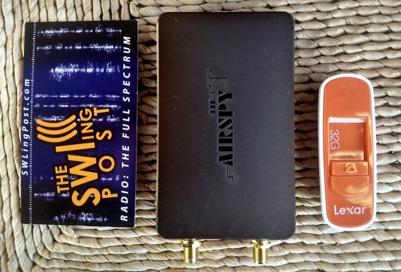
AirSpy’s HF+ was introduced late 2017. Don’t be surprised by its footprint which is similar to a standard business card to its left–this SDR packs serious performance!
If you plan to take your SDR to the field or travel with it, you’ll probably want to choose one that doesn’t require an external power supply. Most late-model SDRs use the USB data cable to power the unit. This means you won’t need to lug an additional power plug/adapter or battery. Still, many professional grade SDRs require an external power supply.
Recording features
If you plan to make spectrum recordings, determine whether you have many options to set the unit’s processing bandwidth. Some SDR applications have robust recording functionality that allows for both spectrum and audio recordings, including advanced scheduling. Some applications don’t even have audio recording or spectrum recording capabilities. Test drive the application in advance to check out their recording functionality. Of course, if recording is your main interest, you’ll also want to set aside some of your budget for digital storage.
Know your goal!
If your goals are somewhat modest––perhaps your budget is quite low, you simply want to familiarize yourself with SDR operation prior to making a bigger purchase, or you only want to build an ADS-B receiver––then you might be able to get by with a $25 SDR dongle. If you plan to use your SDR as a transceiver panadapter during contesting, then you’ll want to invest in a unit that can handle RF-dense environments.
Identify exactly what you’d like out of your SDR, and do your research in advance. Note, too, that many popular SDR models have excellent online forums where you can pitch specific questions about them.
Scoping out the world of SDRs
Three benchmark receivers in one corner of my radio table: The Airspy HF+ (top), Elad FDM-S2 (middle) and WinRadio Excalibur (bottom).
Now that we have a basic grasp on what SDRs are, what components are needed, and what we should research in advance, we’ll look next at some of the SDR options available to us. In Part Two, we’ll look at budget SDRs; those under $200 US in price. In Part Three, we’ll survey higher-end SDR packages.
Stay tuned for more in Part Two (October–click here to read) and Part Three (November–click here to read)! I’ll add links here after publication.
Do you enjoy the SWLing Post?
Please consider supporting us via Patreon or our Coffee Fund!
Your support makes articles like this one possible. Thank you!