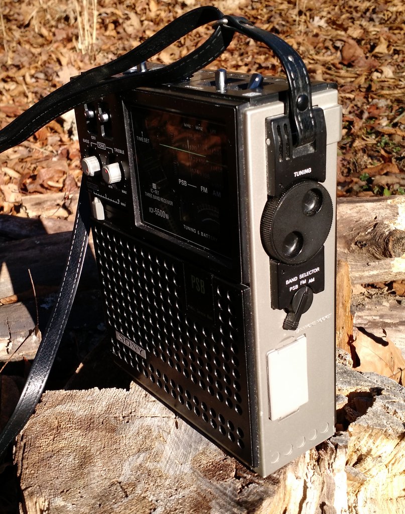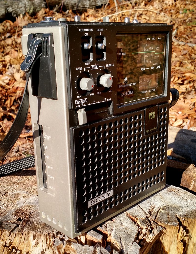
SWLing Post contributor, Gary DeBock, is an acclaimed innovator in the realm of Ultralight DXing–he’s well-known for constantly pushing the envelop on these inexpensive DX receivers.
This time, Gary has published a detailed home-brew project that can turn your stock Tecsun PL-380 into a Mediumwave DX Fiend!
In Gary’s own words:
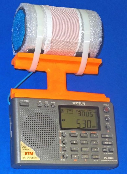
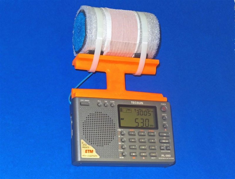
This is the “Science Fiction PL-380” model, with the hobby’s first hard-wired FSL antenna in a portable configuration. The radio’s internal Si4734 DSP chip tunes the high sensitivity MW antenna, so there is no need to peak a variable capacitor. For those who can build or obtain this model, it will be a happy new year indeed!
Many thanks to Gary for the following guest post:
3 Inch FSL Tecsun PL-380 Model
Compact Breakthrough in MW Sensitivity, Selectivity and Portability
By Gary DeBock, Puyallup, WA, USA
January 2016
Introduction
Portable radio enthusiasts were astonished when Silicon Labs first introduced their innovative Si4734 DSP chip in 2009—the pocket radios empowered by this new component had amazing DSP-enhanced selectivity. Although the relatively lame stock loopsticks designed by the Kchibo and Tecsun companies seriously limited MW sensitivity there was no shortage of fanatical hobbyists designing upgrade loopsticks in an effort to correct this deficiency. The 7.5” loopstick transplant boosted the MW sensitivity of the PL-380 model up to a much improved level, and it became the most popular modification in our Ultralight radio group. But in 2011 another huge breakthrough was about to capture the fascination of our DXing niche group—Graham Maynard published his original Ferrite Sleeve article, and the innovative antenna’s sensitivity made our humble pockets radios perform like real transoceanic DXing contenders. This was very thrilling—but was there any possible way that the awesome selectivity from the Si4734 DSP chip and the awesome sensitivity provided by the FSL antenna could somehow be combined in a self-contained breakthrough portable, with lightweight portability as an added bonus?
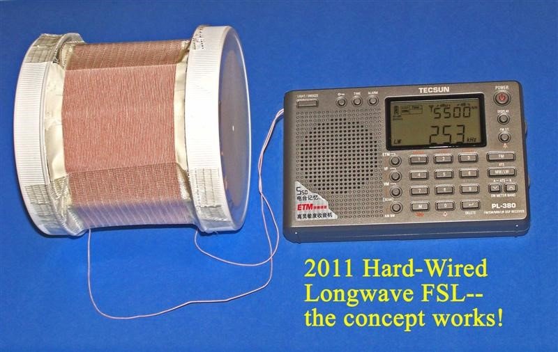
The fact that an Si4734 DSP chip could successfully tune an external antenna was demonstrated by various experimenters (including me) in 2011—a hard-wired 3” Longwave FSL design worked quite well for me in early 2011, and although it was far too heavy to consider attachment to the PL-380 the validity of the hard-wired FSL concept was proven to my satisfaction (see photo at right). The challenge has always been to create a hard-wired FSL that would offer both high MW sensitivity and lightweight portability— a value tradeoff that made this project especially intriguing.
After testing various designs I finally settled on a 3” FSL composed of the lightweight Russian surplus 100mm x 20mm x 3mm ferrite bars. These bars provide a unique balance of high sensitivity and lightweight portability, and the cylindrical shape of the FSL apparently provides the fringe benefit of exceptional nulling capability. The PL-380’s Si4734 chip easily tunes the antenna for breakthrough MW sensitivity from 521-1701 kHz, and provides excellent 1 kHz DSP selectivity as well. The weight of the FSL-enhanced PL-380 is within reason to maintain the concept of easy portability, and its modest size may actually convince airport security agents that it is indeed a radio and antenna combination. Overall the project has been a very satisfying effort to combine the awesome capabilities of both the Si4734 DSP chip and the new FSL antenna– resulting in a breakthrough “travel portable” with astonishing MW-DXing performance.
Project Overview
This modification procedure will convert the Tecsun PL-380 AM-LW-FM-SW portable from a modest-performing Medium Wave receiver into an exceptional one, with a significant enhancement of Longwave performance as well. The process involves some close-order soldering on a crowded PL-380 circuit board, and should only be attempted by those will good close up eyesight, steady hand coordination and some soldering experience. Certain component parts (such as the 100mm x 20mm x 3mm ferrite bars, the 2.25” Funnoodle inner cores and the orange plastic antenna frames) may be in short supply depending upon current demand, and it is recommended that all these collected prior to starting the project.
Since major portions of this project involve duplication of procedures contained in the PL-380 7.5” Loopstick Transplant article, reference is made to various steps and instructions in that article (posted at
http://www.mediafire.com/view/du3sr5cd9thqvau/7.5inch-LS-PL380.doc ). As such, hobbyists who have successfully completed the 7.5” loopstick transplant project on a PL-380 will find this procedure relatively simple, with only the 3” Bar FSL construction as a new challenge. The resulting FSL-enhanced PL-380 truly provides a quantum leap in MW-DXing performance over the stock model, but reasonable care is necessary to protect the modified portable from sudden drops or mechanical shocks. Completion of the finished radio should provide a great level of satisfaction and hobby enjoyment, especially during travel opportunities where external antennas are impractical or forbidden.
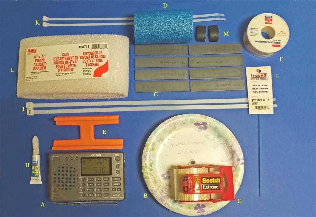
Construction Parts Required
A) Tecsun PL-380 AM-LW-FM-SW Receiver (available from many sources, including this eBay listing at $46.99 with free shipping to the USA) http://www.ebay.com/itm/Tecsun-PL380-DSP-AM-FM-Shortwave-LW-PLL-Radio-Receiver-PL-380-/251783558999?hash=item3a9f783757:g:t0EAAOxylpNTTan7
B) 37 feet of 250/46 Litz wire http://www.ebay.com/itm/Litz-wire-250-46-0-04-mm-for-crystal-radio-coil-Loop-antenna-100-/160804560511?hash=item2570b2de7f:m:m9fkDfLaAd59_UEmrp1po5w
C) 8 Russian surplus 100mm x 20mm x 3mm ferrite bars (availability currently uncertain– author has a limited supply. An eBay source may reappear for future orders, since many of these bars are presumably still in eastern Europe)
D) 4″ length of 2″ diameter Fun Noodle inner foam core
http://www.amazon.com/Aqua-World-223-Fun-Noodle/dp/B0017QABEQ/
E) Precut orange plastic antenna frame (cut from Ace hardware 48″ plastic level, with 5″ long bottom dimension and 4.5″ top dimension– cutting instructions to follow). NOTE: each Ace Hardware 48” level has enough material to make two FSL antenna frames.
F) Rite Aid 1″ wide waterproof tape (1 roll)
G) Scotch “Extreme” shipping tape (1 roll)
H) Tube of Duro Super Glue (or equivalent), .07 ounce
I) 6 inches of 1/16″ diameter shrink tubing
J) Two 18″ lengths of 125 lb. test plastic tie wraps
K) Two 16″ lengths of 75 lb. test plastic tie wraps
L) Oatey foam pack (4” wide)
M) Two 3/4″ x 1″ strips of 1″ I.D. rubber heater hose
Miscellaneous: Solder, 25w (low heat) soldering iron, hacksaw (or power miter saw), screwdriver set, sandpaper (optional)
PL-380 Preparation
Before voiding the warranty on your new PL-380, it’s a good idea to ensure that it has no existing problems which might require warranty service. (Ha!)
Install batteries in the radio and give it a test run on all four bands, checking the tuning encoder, clock, volume control, speaker, headphone jack, display functions and digital searching modes. Make sure that the radio is working properly in all functions before starting the modification procedure, since the eBay sellers are unlikely to show you any sympathy after you tear out the stock loopstick. It’s also a good idea to check out the Medium Wave weak signal reception with the PL-380 stock loopstick before starting the modification, to establish a benchmark of performance against which the new 3” FSL’s DXing performance will be compared.
STEP-BY-STEP CONSTRUCTION
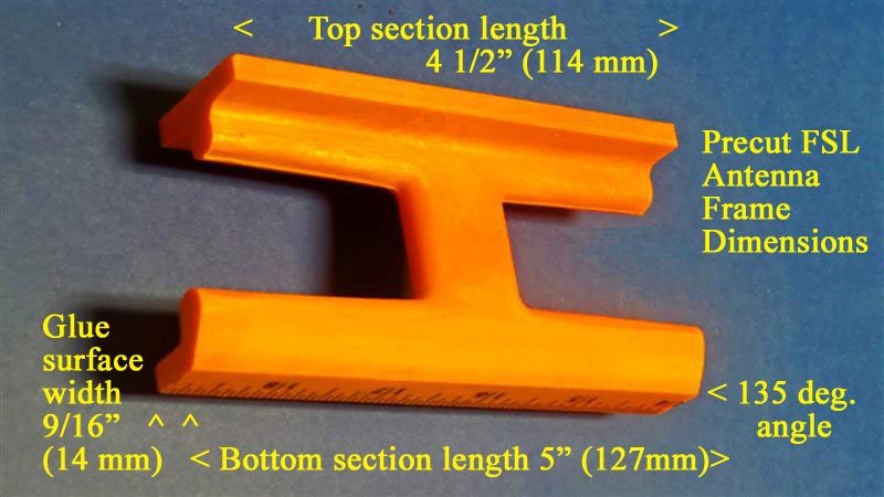
1) Follow the detailed cutting procedures in steps 1-9 of the loopstick transplant article (using either a power miter saw or hacksaw) to prepare the FSL antenna mounting frame, HOWEVER please note that the top section length for this project is 4 ½” (114 mm), NOT 8” as in the loopstick transplant project. The finished precut frame should resemble the picture above, with the top section flat, and the bottom section back edge trimmed to allow full use of the radio’s whip antenna. The frame’s entire bottom section (including the glue surface) is identical in both the loopstick and FSL transplant projects.
2) Follow the detailed procedures in steps 17-22 of the loopstick transplant article to prepare the PL-380 cabinet for the FSL transplant procedure.
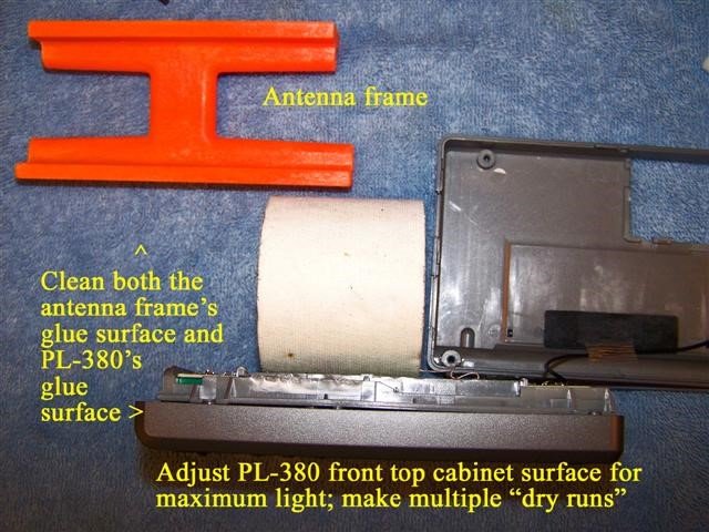
3) Refer to the photo above. Place the prepared PL-380 cabinet in the vertical position as shown, with a paper roll (or other item) to keep the cabinet in the vertical position. If necessary sand the edges (only) of the antenna frame’s glue surface to ensure that no cutting debris or rough edges will cause an uneven gluing surface. Use a clean, damp cloth or paper towel to remove all dust and debris from both the antenna frame and PL-380 glue surfaces, then wipe them thoroughly dry. Ensure that maximum light shines on the PL-380’s top glue surface (as shown in the photo below), then practice making multiple “dry runs” of placing the antenna frame directly centered on the PL-380’s front top cabinet surface, with its front edge lined up with the PL-380’s beveled front edge. You will only get one chance to place the frame accurately when the super glue is on the PL-380 surface, so make sure that you know exactly what to do! The antenna frame should sit completely flat against the PL-380 cabinet, and slide across it smoothly if such a test is made. If not, sand any rough edges on the antenna frame’s glue surface and repeat the cleaning procedure.<
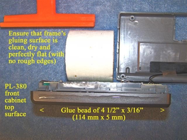 4) Refer to the photo above. After ensuring that you are fully prepared for accurate placement of the antenna frame on the PL-380 cabinet, place a 4 1/2” x 3/16” bead of super glue (114 mm x 5 mm) on the PL-380’s front top cabinet surface, as shown in the photo. Refer to the photo on the top of the next page. Ensure that the front side of the antenna frame (as shown) is facing you, then place the antenna frame in a centered position flat against the PL-380 cabinet, with its front edge lining up with the front beveled edge of the cabinet, as shown in the photo. Press the antenna frame down firmly against the cabinet for about one minute, scraping away any excess glue from the front and back edges with a small, flat jeweler’s screwdriver. It is especially important to remove any excess glue from the back edge of the antenna frame in order to allow the PL-380’s back cabinet to close normally. After completion of this step place the PL-380 (with the attached antenna frame) in a secure area until the FSL antenna is constructed.
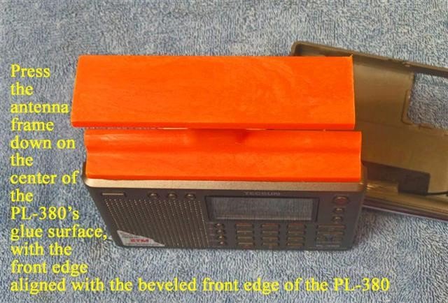
CONSTRUCTION OF FSL ANTENNA
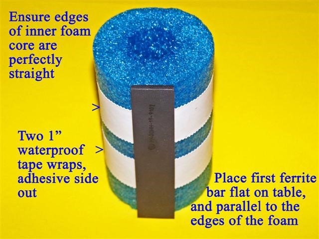
5) Refer to the photo above. Ensure that the end edges of the 4” Funnoodle inner foam core are perfectly straight before performing this step. Place the inner foam core flat on a table, standing on one of its edges as shown. Take the roll of 1” wide waterproof tape and wrap two turns tightly around the inner foam core as shown in the photo, with the adhesive side out. Ensure that the two turns are wound tight enough so that they will not slide up or down the inner foam core. Take the first 100mm ferrite bar and press it firmly against the waterproof tape with its short edge completely flat on the table, and long edges completely parallel to the edges of the inner foam core (as shown). It is important to place this first bar accurately, in order to start an accurate pattern for the set of 8 bars.
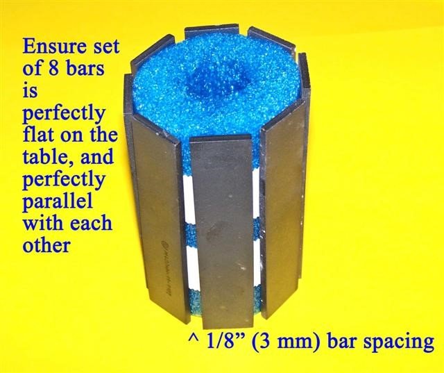
6) Refer to the photo above. Press another of the 100mm ferrite bars against the waterproof tape in a position where it is perfectly flat on the table and perfectly parallel with the first bar, with 1/8” (3 mm) spacing between the bars. Continue to place the other 6 bars on the inner foam core in exactly the same way, ensuring that all 8 bars are flat against the table and parallel with each other, having 1/8” (3 mm) spacing between them. If necessary (after placing all 8 bars on the tape), even out the spacing by moving certain bars slightly so that the gaps between them are all equal. The set of 8 bars will be compressed in the next step to form an octagonal pattern.
7) Refer to the photo above. Place a 75 lb. test plastic tie wrap around one edge of the set of 8 bars as shown, 1/2” (12 mm) from the ends of the bars. Slowly and carefully compress the set of 8 bars as shown, tightening up the slack in the plastic tie wrap gradually as you compress the set of bars. Continue this gradual process until the set of 8 bars forms an octagonal (stop sign) pattern, with the bars barely touching each other on their compressed edges. At this point take up any remaining slack in the plastic tie wrap, and stop compressing the bars. Repeat this process on the other side of the ferrite bars with another 75 lb. test plastic tie wrap, ensuring that the bars form another octagonal pattern, with their compressed edges barely touching each other. Again take up the slack in the plastic tie wrap, and then use diagonal cutters to trim the excess ends of the plastic tie wraps.
8) Refer to the photo above. Place the prepared set of 8 bars flat on the table on one of its ends, as shown. Take the roll of 1” waterproof tape and tightly wrap two turns of tape around the ferrite bars as shown, with the adhesive side out. Space these two wraps evenly as shown, ensuring that they are tight enough not to slide up and down the bars.
9) Refer to the photo above. Take the Oatey 4” foam pack, remove the center staple and locate a 9” (23 cm) long length of this foam which is free of any holes or imperfections. At the beginning of this 9” (23 cm) long length of foam cut a perfectly straight line perpendicular to the edges of the foam. Press this straight edge of foam down tightly against the waterproof tape as shown, with the edges of the 4” Oatey form lining up with the edges of the bar assembly’s inner foam core. Wrap this Oatey foam tightly around the waterproof tape until the foam touches the plastic tie wrap clamps.
If necessary, re-wrap the foam tightly so that it is centered on the ferrite bar assembly.
 10) Refer to the photo above. Pull the Oatey foam wrap tightly around the bar assembly, then cut a straight edge to mate evenly with the previously cut straight edge. Before pressing this edge down on the tape cut side notches in the foam where the tie wraps clamps are located, as shown. The press this foam edge tightly down on the tape, mating evenly with the previously cut foam edge. Ensure that there are no gaps or overlaps in the foam edges; if necessary, pull the foam wrap once again all around the bar assembly and cut a new straight edge that will mate evenly, with no gaps or overlaps. Finally, secure this newly cut foam edge with a 2 1/2” (64 mm) strip of waterproof tape, as shown.
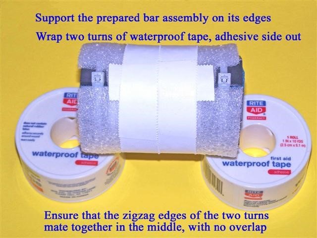
11) Refer to the photo above. Support the edges of the prepared bar assembly so that it will be raised off of the table. Wrap two turns of the 1” waterproof tape tightly around the center of the prepared bar assembly, adhesive side out (as shown). When wrapping the second turn, ensure that the inner zigzag edge of the waterproof tape mates evenly with the inner zigzag edge of the first turn of tape, with no overlap or gap.
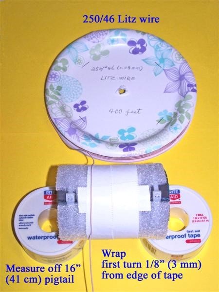
12) Refer to the photo above. Take your reel of 250/46 Litz wire and measure off 16” (41 cm) of wire from the end. Press this exact point down on the waterproof tape 1/8” (3 mm) from the left edge of the waterproof tape, as shown in the photo. While pressing down this Litz wire point while the wire is in a position parallel to the waterproof tape (as shown) pick up the bar assembly with one hand and the Litz wire reel with the other hand, pulling the Litz wire tightly around the circumference of the bar assembly in a straight, parallel manner to begin the first Litz wire turn. Ensure that this first turn stays 1/8” (3 mm) away from the left edge of the waterproof tape all around the bar assembly, then start the second turn directly adjacent to the first turn, ensuring that no gaps or crossovers occur while winding the turns. Carefully continue this process until 36 total turns have been wound around the bar assembly, which should leave the Litz wire coil in a centered position, similar to the photo below. NOTE: This coil is designed to provide an inductance of 350 uH.
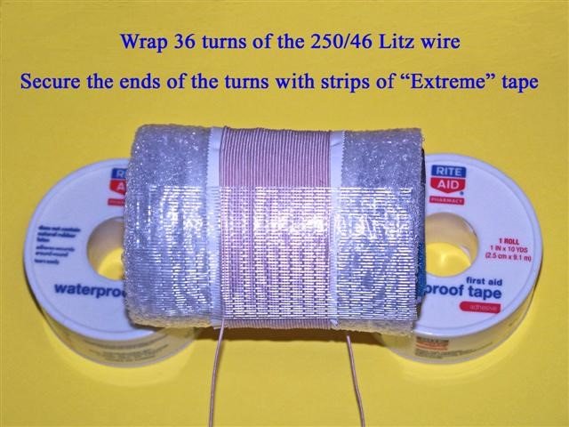
13) Refer to the photo above. After 36 turns have been wound on the bar assembly, ensure that there is still a 16” (41 cm) length of loose Litz wire leading up to the first coil turn. Then place a strip of Scotch “Extreme” tape along the length of the bar assembly, with the lower edge of the tape along the point where the first Litz wire turn begins (as shown), and with the tie wrap clamps in back of the assembly. Press the tape down firmly to lock the coil into place. In the same manner, turn the bar assembly over and place another strip of “Extreme” tape along the bar assembly, with the lower edge of the tape along the point where the last Litz wire turn ends (where the wire leaves the coil), avoiding the tie wrap clamps. There should be about 2” (51 mm) of space between the two “Extreme” tape strips, and both loose Litz wire ends should be parallel as they come off of the coil. Press the second “Extreme” tape strip down firmly to lock the coil into place. Finally, measure off another 16” (41 cm) of loose Litz wire from the coil, cutting the Litz wire at that point.
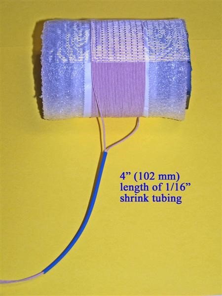
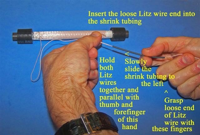
14) Refer to the photo above. Cut a 4” (102 mm) length of the 1/16” shrink tubing, and then cut a very short piece off of the ends of the Litz wires to ensure that these ends have the smallest and smoothest possible profile to be run through the shrink tubing. Run one end of the Litz wires through the shrink tubing until about 3 inches of wire extend from the tubing. Carefully insert the other end of the Litz wire through the shrink tubing, and use the procedure (and photo) in Step 30 of the Loopstick Transplant article to run the second Litz wire through the shrink tubing, as shown. The related photo for that procedure is included below.
15) Place the previously prepared PL-380 and antenna frame assembly flat on the table, with a protective cloth to keep the front panel display from damage.
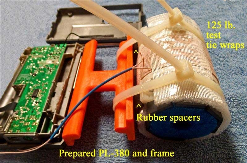
Take the prepared FSL antenna assembly and place it in the position shown, with the Litz wire shrink tubing running along the back side of the antenna frame and the lower edge of the FSL assembly next to the top of the antenna frame. Place the two 3/4” x 1” strips of rubber heater hose in the two positions shown, in between the antenna frame and the FSL antenna and also in between the coil and the FSL edges, with the longer rubber strip dimensions parallel to the FSL edges. Start the two 175 lb. test plastic tie wraps in the positions shown (down the center of the rubber spacer strips), ensuring that the rubber spacer strips remain between the FSL assembly and the antenna frame, and that the spacer strips are centered at the very bottom of the FSL assembly. Also ensure that the Litz wires are in the position shown, with no pinching or binding between the FSL assembly and antenna frame. Slowly and carefully tighten the first plastic tie wrap while ensuring that the rubber spacer strip remains in the proper position. Tighten this plastic tie wrap only enough to securely hold the FSL assembly, and do not tighten it to the point where the ferrite bars’ octagonal pattern begins to distort. In a similar manner, carefully tighten the other plastic tie wrap while ensuring that the rubber spacer strip remains in the centered position, in between the antenna frame and FSL assembly. Once again, tighten this tie wrap only enough to securely hold the FSL assembly, and not to the point where the ferrite bars’ octagonal pattern begins to distort. When this process is complete the large plastic tie wraps’ clamps should be in the position shown, lined up with each other and in a position to support the radio/FSL combination when the model is laying down flat, on a table. Cut off the excess tie wrap lengths.
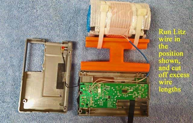
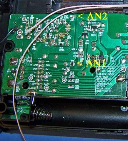
16) Refer to the photo above. Temporarily place the Litz wires down along the radio’s circuit board in the position shown. Locate the detailed circuit board antenna connection points “AN1” and “AN2” in the close up photo at the top of the next page. After locating these two circuit board connection points (with the Litz wires running in the position shown in the photo at left) place one of the Litz wires over the “AN1” circuit board point, and the other Litz wire over the “AN2” circuit board point. Then measure out about 1” (25 mm) extra
Litz wire past these two circuit board connection points, and after making sure that the Litz wires are still in the approximate position shown in the photo at the beginning of this step, cut one (shorter) Litz wire 1” (25 mm) past the “AN2” circuit board point, and one (longer) Litz wire 1” (25 mm) past the “AN1” circuit board point.
17) Refer to the photo below. Temporarily place the Litz wires outside of the radio as shown, and install a 1 1/2” (38 mm) long section of shrink tubing over both Litz wires, and a 1” (25 mm) long section of shrink tubing over the longer Litz wire. Position both sections of shrink tubing as shown in the photo below. Place some type of protective material under the Litz wire so that the soldering procedure (in the next step) will not damage your work surface.
NOTE: The proper procedure of tinning the ends of the Litz wires requires that all of the individual Litz wire strands be soldered together at the ends. This requires a clean, shiny solder connection all around the circumference of the Litz wire ends for at least 1/8” (3 mm). When preparing the ends of the Litz wires in the next step, ensure that the ends are tinned in this manner before continuing.
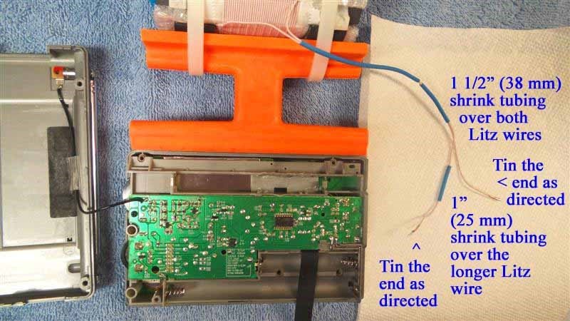
18) Refer to the photo above. Carefully tin the ends of both Litz wires in the manner described above, working around the circumference of the Litz wire ends with a clean soldering iron for at least 1/4” (6 mm). After doing this, cut off the tinned section on both ends to a length of 1/8” (3 mm). When viewing the ends of the Litz wires after tinning, the entire 1/8” (3 mm) length should be bright and shiny all around its circumference, as shown in the photo at the top of the next page. The cut surface of the Litz wire (the circular face) should also be bright and shiny, with one solid surface of melted solder.
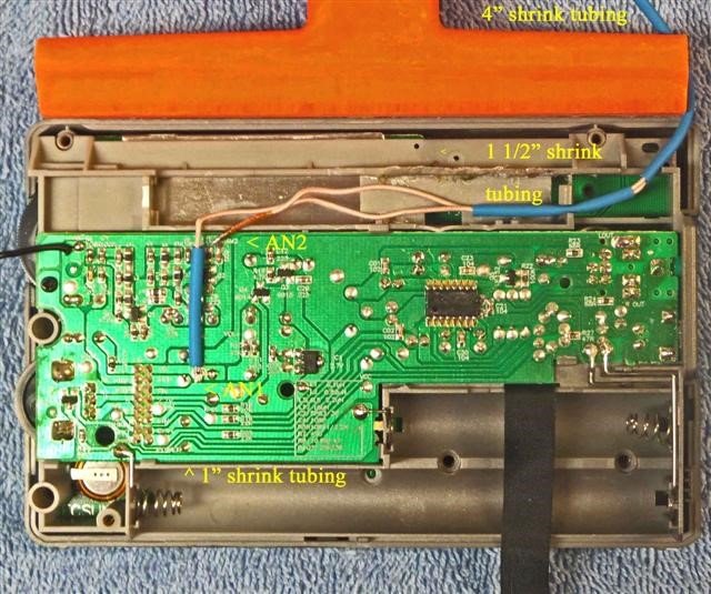
19) Refer to the photo above. Take the prepared ends of the Litz wires and route them as shown in the photo above, with the 1 1/2” (38 mm) section of shrink tubing placed in the cabinet clamp as shown, and the end of the 4” (102 mm) section of shrink tubing (coming from the FSL coil) also positioned as shown (where it will be run through the empty wrist strap hole, in the back cabinet side panel). Before placing the 1 1/2” (38 mm) long section of shrink tubing in the cabinet clamp refer to the picture at the top of the next page, and ensure that there will be sufficient slack in the 4” (102 mm) shrink tubing to be run from the FSL coil to the wrist strap hole (3/8” or 9 mm down from the top of the cabinet) without binding.
Ensure that the circuit board points “AN1” and “AN2” still have a small amount of melted solder on them (after removal of the PL-380 stock loopstick, as described in the Loopstick transplant article). Also ensure that there is no excessive length in either of the Litz wires, since these both must be positioned as shown (if necessary, cut one or both to the proper length, and re-tin them as described in the previous step). Place the end of the shorter Litz wire (going to the AN2 circuit board point) down in a horizontal position as shown, and using a MINIMUM of heat (and no additional solder), solder the pre-tinned Litz wire end to the AN2 circuit board point while the wire is in a horizontal position. Carefully observe the connection to ensure that there are no solder bridges to the adjacent circuit board components. After ensuring this, temporarily move the 1” (25 mm) section of shrink tubing away from the end of the longer Litz wire, and following the detailed procedure described for the AN2 connection above, carefully solder the end of the longer Litz wire to the AN1 circuit board point in a horizontal position as shown, using a MINIMUM of heat (and no additional solder). Once again ensure that there are no solder bridges to adjacent components, and that the wire is in a horizontal position, as shown. Then slide the 1” section of shrink tubing down over the Litz wire to the position shown in the photo.
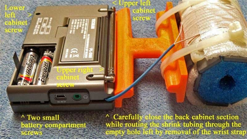
20) Refer to the photo above. After ensuring that your Litz wire connections and the wires’ positions resemble those in the previous photo, take the PL-380’s back cabinet section and carefully bring it close to the radio, as shown in the photo. Ensure that the whip antenna’s lead-in wire is not pinched, and also ensure that the 4” (102 mm) section of shrink tubing is routed is a position close to the empty wrist strap hole in the back cabinet, as shown. As a first step, carefully mate the radio’s back cabinet to the radio’s right side (the one opposite the wrist strap hole) while continuing to guide the shrink tubing through the wrist strap hole. Finally, center the shrink tubing in the wrist strap hole while mating the remaining (left) side of the cabinets together. Ensure that the shrink tubing is not pinched or extremely tight as it is clamped down in this hole. While holding the two cabinet sides together move the whip antenna up and away from the cabinet screw hole underneath, and insert the first cabinet screw, tightening it temporarily to keep the shrink tubing in position. Then insert and tighten the left upper and left lower cabinet screws thoroughly, while snapping the right lower cabinet sections together. Finally, after ensuring that the Litz wires’ shrink tubing is still in the center of the wrist strap hole without any binding or excessive stress, tighten the final cabinet screw near the whip antenna base. Reinstall the two small battery compartment screws and reinsert batteries.
INITIAL TESTING If you are not familiar with the PL-380, make sure that you study the owner’s manual to find the location of basic operating controls. It is important to initially test the radio in a location free of computer noise or other RF pollution—preferably in an outdoor location where its capabilities can be appreciated. Refer to the photo on the next page. Turn on the radio and select the Medium Wave band (530-1700 kHz in North America) and set the AM bandwidth control to the most selective (1 kHz) position (NOTE: This position also provides maximum MW and LW sensitivity for the model, although the higher audio frequencies are limited somewhat by the sharp DSP filtering). If your FSL antenna transplant is working properly you should notice an EXCEPTIONAL increase in the signal strength of weak fringe stations relative to the stock PL-380 model, and a very significant increase in fringe station strength relative to a 7.5” loopstick PL-380 model. Check fringe station strength across the band, and you should notice MW reception far superior to that of any stock portable in your collection. If you are not receiving any MW signals the problem is usually easy to trace—either one of the PL-380 circuit board connections is shorted to adjacent components because of too much solder, or the physical stress on the Litz wires (because they were not soldered in a horizontal position) has caused the circuit board connections to break off and separate from the board. In the first case you can attempt to remove excess solder by turning the circuit board upside down and melting the excess solder onto the tip of your soldering iron (or using a “solder sucker” in a normal position), but in the second case you will probably need a technician to restore proper function to your radio. Fortunately both of these problems are rare, and can be entirely avoided by carefully following the instructions in Steps 18 and 19.
OPERATION
The triple advantage of superior FSL sensitivity, powerful audio amplification and sharp DSP selectivity provide this breakthrough model with exceptional weak-signal performance for a portable—to the extent that after a few DXing sessions the operator may have the impression that the realm of science fiction has been approached. The cylindrical shape of the FSL antenna seems to provide a bonus capability of unusual nulling function as well, so that multiple weak signals can be received adjacent to (or on the same frequencies as) local pests.
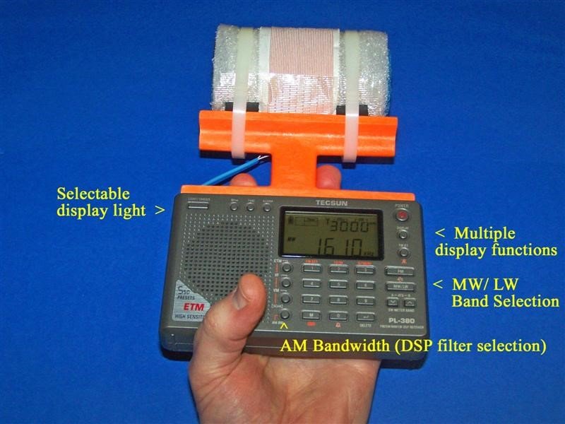
During DXing sessions it is a good idea to support both the PL-380 and FSL antenna frame in the same hand (as shown in the photo above), and also to avoid sudden mechanical stress or bumps to the antenna frame. When constructed according to this article the glue bond between the antenna frame and PL-380 is sufficient for routine operations, but the DXer should exercise care to avoid bumps, drops or other stress. The FSL antenna itself is fairly rugged, as constructed.
Refer to the photo on the previous page. The PL-380 has many digital search functions and advanced capabilities for a pocket radio, but some of the functions of particular interest to the transoceanic DXer are described here. The “AM Bandwidth” switch allows you to choose different levels of DSP filtering to limit splatter from domestic pests, and is usually left in the 1 kHz position for the narrowest filtering while chasing transoceanic DX (although this position does cut off some of the high frequency audio from the desired DX station). The 9/10 kHz switch allows you to change the tuning steps of the radio from the North American (10 kHz) band system to those of the European/ African/ Asian/ Pacific band system (9 kHz), depending upon your preferred DX targets. The MW / LW switch allows you to switch over to Longwave DXing—and you will be pleasantly surprised to discover that your newly installed 3” Bar FSL antenna is FAR more sensitive on the Longwave band than the stock PL-380 loopstick. Finally, the Display switch offers you multiple options while chasing transoceanic DX—you can have a 24 hour clock display, a display of the alarm time set in the radio, a constantly changing readout of DX signal strength and S/N ratio, or a temperature display (in either Celsius or Fahrenheit).
Because the antenna frame has been trimmed to allow full operation of the PL-380’s whip antenna to receive SW and FM signals, it’s possible to check the Shortwave parallels of Medium Wave DX stations (and switch back and forth) within a couple of seconds. In general, this “science fiction” PL-380 model’s sensitivity and selectivity will allow you to experience the most exciting AM-DXing fun that a portable can offer—and do so at an unbeatable price.
This hard-wired FSL-enhanced PL-380 model is the first in a series of portables designed to be the ultimate “travel radios,” with DXing potential superior to any stock design. It has been a great thrill to design, construct and introduce this model, which is pretty fanatical in both its appearance and DXing capabilities. My hope is that its function will inspire those who build and use it, and help them share my impression that the MW-DXing hobby has a very innovative and exciting future!
73 and Good DX,
Gary DeBock
Gary, I can only imagine the time and patience it took to document this procedure. Once again, thank you so much for doing so! I have a Tecsun PL-380 and I will–some day–make this “science fiction” mod!


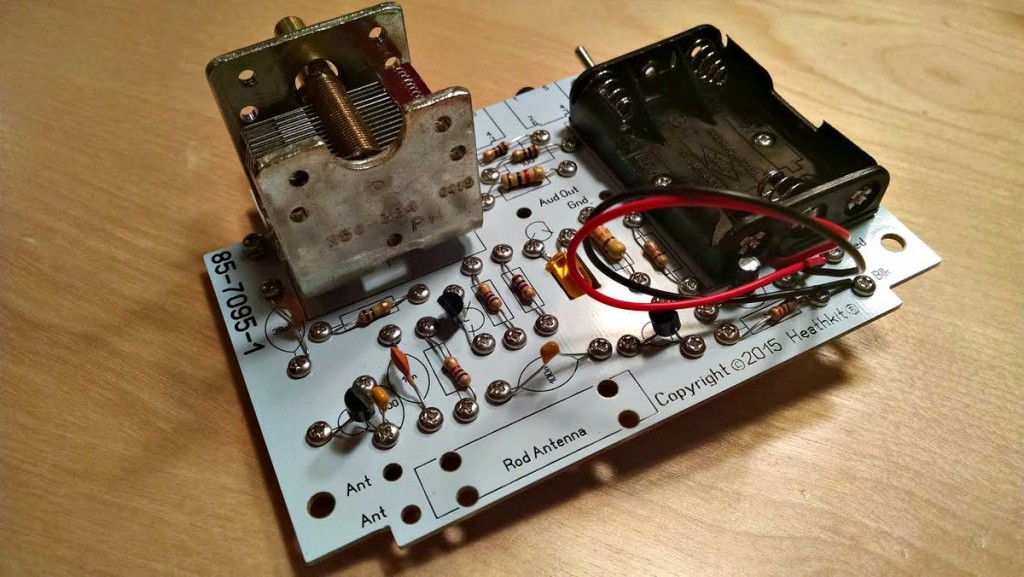
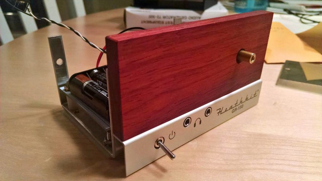
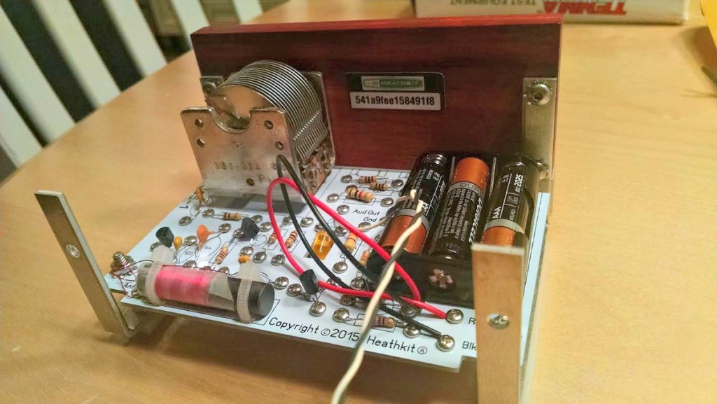
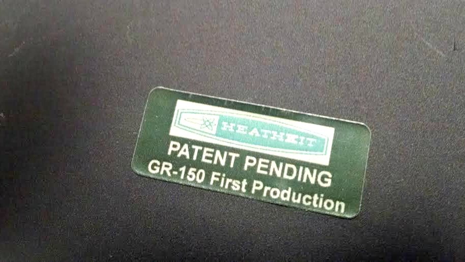
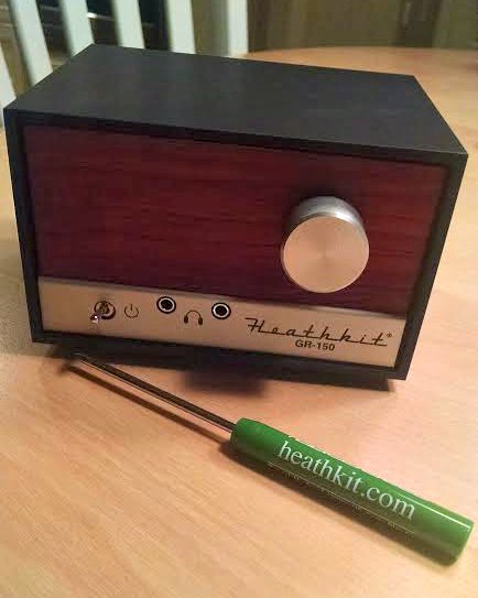
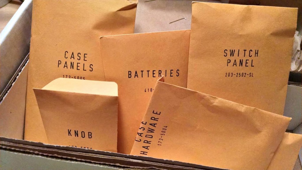
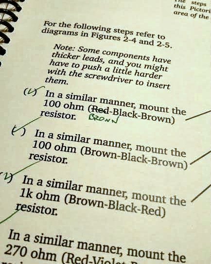
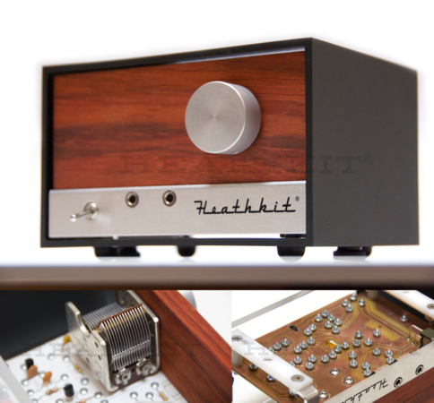 Many thanks to SWLing Post contributor, James Surprenant (AB1DQ), who shares this review and photos of the new Heathkit Explorer Jr. TRF AM radio receiver kit:
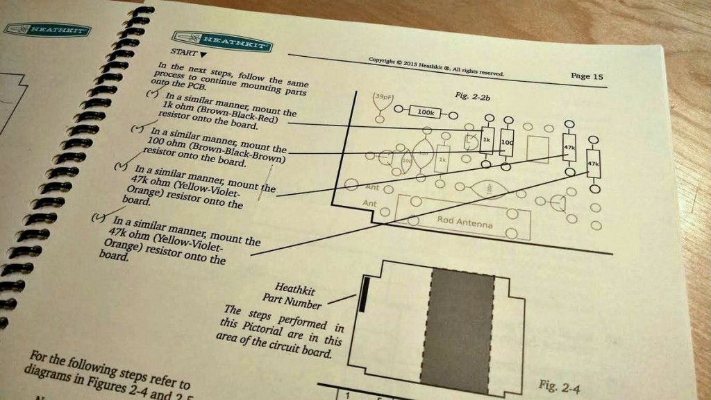
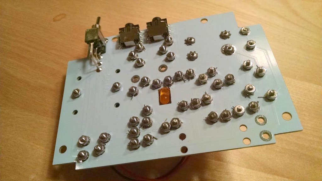
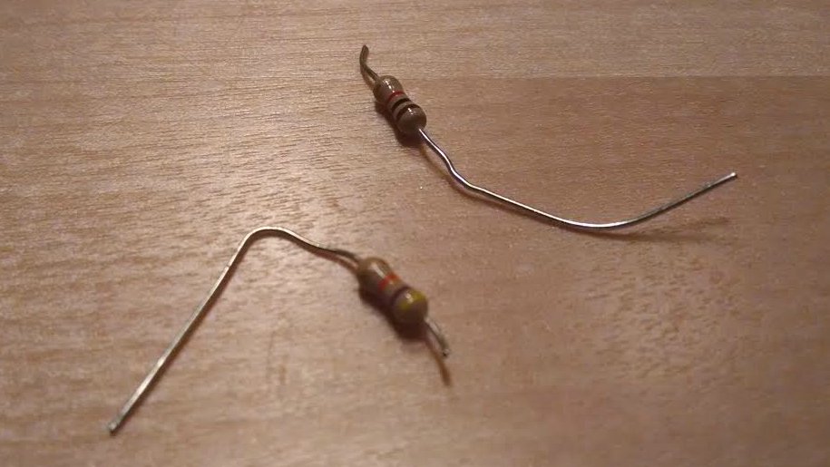 On the downside, I managed to sheer off the leads on TWO resistors when tightening the screws. Fortunately I was able to replace the busted resistors from my on-hand stock.