UPDATE 11 May 2020: We recently learned that the MSI.SDR software defined radio dongle in the following post and tutorial is a clone of the SDRplay RSP1 SDR. We did not realize this when the post was published. Grayhat had done research prior to purchase and believed it not to be a clone, but only using the same chipset as the RSP1 (hence the compatibility with SDRuno). We have confirmed that it is indeed a clone now via SDRplay (clear here to read more via the excellent RTL-SDR blog). What follows isn’t an SDR review. Indeed, Grahat’s post has little to do with the receiver and much, much more to do with building proper antennas! We’ve removed links to the MSI.SDR and would encourage you to invest in the excellent SDRplay RSP1a instead (click here to read our RSP1a review). Thank you for understanding!
Many thanks to SWLing Post contributor, Grayhat, who shares the following guest post. He lives in Italy and has been in lock-down since the beginning of the pandemic. He pitched the idea of building an entire SDR setup from scratch–receiver and antennas–for less than 150 Euros (roughly $163 USD). I thought it was a brilliant idea and I believe he thoroughly enjoyed the challenge of sourcing the components and building a mini antenna farm on his balcony while in quarantine:
From Zero to SDR
by Grayhat
What follows doesn’t pretend to be some kind of “definitive guide” or “last word”, on the contrary, it’s aimed at people who have little or no experience with SDR but want to try putting together a decent station without paying an arm and a leg.
The idea of writing this came to me after reading a number of messages and discussions on various online groups/forums, in a lot of cases, someone bought an SDR (usually the ones coming with a telescopic whip antenna), and after connecting it was expecting it “just to work” or, better said, pretending that the SDR connected to that whip (usually placed on a table right near the computer) could receive ANY POSSIBLE signal, including transmissions coming from the “dark side of the moon.” 🙂 Those folks got scared by the fact that the SDR “didn’t work” and decided to give up; now, this short “guide” should allow anyone to setup what’s needed to have a working SDR
My self-imposed limitations for this project/experiment were the following:
- The whole setup shouldn’t cost more than 150 Euros so that, if after trying the SDR one doesn’t like it, (s)he won’t have paid $$$, otherwise, if (s)he decides to keep it, the resulting station will allow for further expansion/improvement
- The available space was considered to be that of an apartment, that is, no large field to put up huge wire antennas or to raise towers, the limit was the one of a balcony (in my home) that is 8 meters (max antenna length) by 3 meters (available height) by 2 meters (balcony width)
- The whole setup should be simple and straightforward, no need to solder components or to build special types of antennas
- Given the current Covid-19 sheltering, most components should be available online, while for others one may arrange with whatever is locally available (e.g. duct tape)
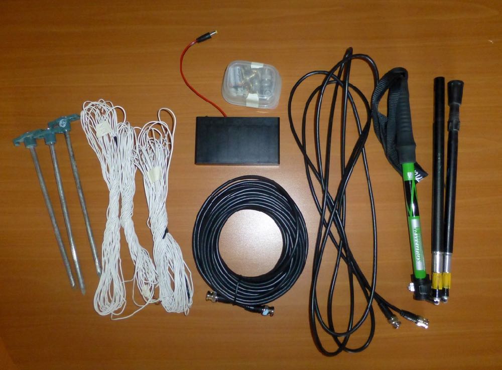
With the above limitations in mind, I took pencil, paper and rubber eraser (high-tech instruments, indeed) and started writing down a list of the needed stuff, after some writing, wiping and second thought, I came out with the following list, available on Amazon:
Bill of materials
- Insulated wire (100mt x 2.5mm)
- Paracord (100mt x 3mm)
- Nylon cable tiers (100 pcs x 2.5mm x 100 mm)
- Waterproof electrical junction box
- NooElec Balun 1:9 V2
- iChoose Ltd RG58+BNC coax, 15mts
- BNC female to SMA male adapter (2 pcs)
- Snap-on ferrite chokes for 9mm cables (10 pcs)
- MSI.SDR 12 bit ADC was used for this experiment before realizing it is a clone of the SDRplay RSP1. We recommend the RSP1a as an upgrade.
The above includes all the needed stuff to put together a number of wire antennas (random wire, random dipole, loop…) the coax to connect the SDR, a balun to match the coax to the antenna and the accessory parts needed to put up the antenna. The selected SDR isn’t the common “RTL SDR” type, not that they don’t work, but their 8 bit ADC is far from being a good performer, so I decided to pick a different SDR which offers a 12 bits ADC and which also “presents itself” to the system as an SDRplay RSP1.
[Please note: we’ve since learned from SDRplay that the MSI.SDR is indeed a clone of the SDRplay RSP1. Here’s a post from the RTL-SDR blog confirming this. We recommend purchasing the RSP1a as a better alternative.]
Anyhow; all I can say is that after some tests, the MSI.SDR is a quite good unit and offers quite a lot of bangs for the buck, so I believe it may be a good unit for people willing to get their feet wet with SDRs
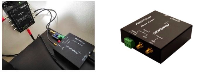
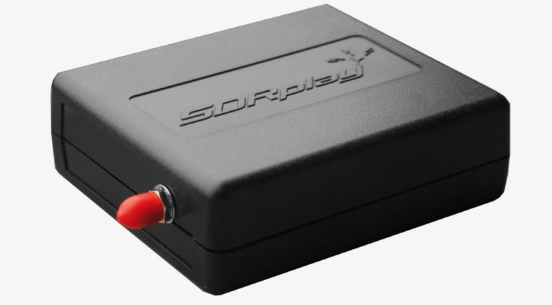
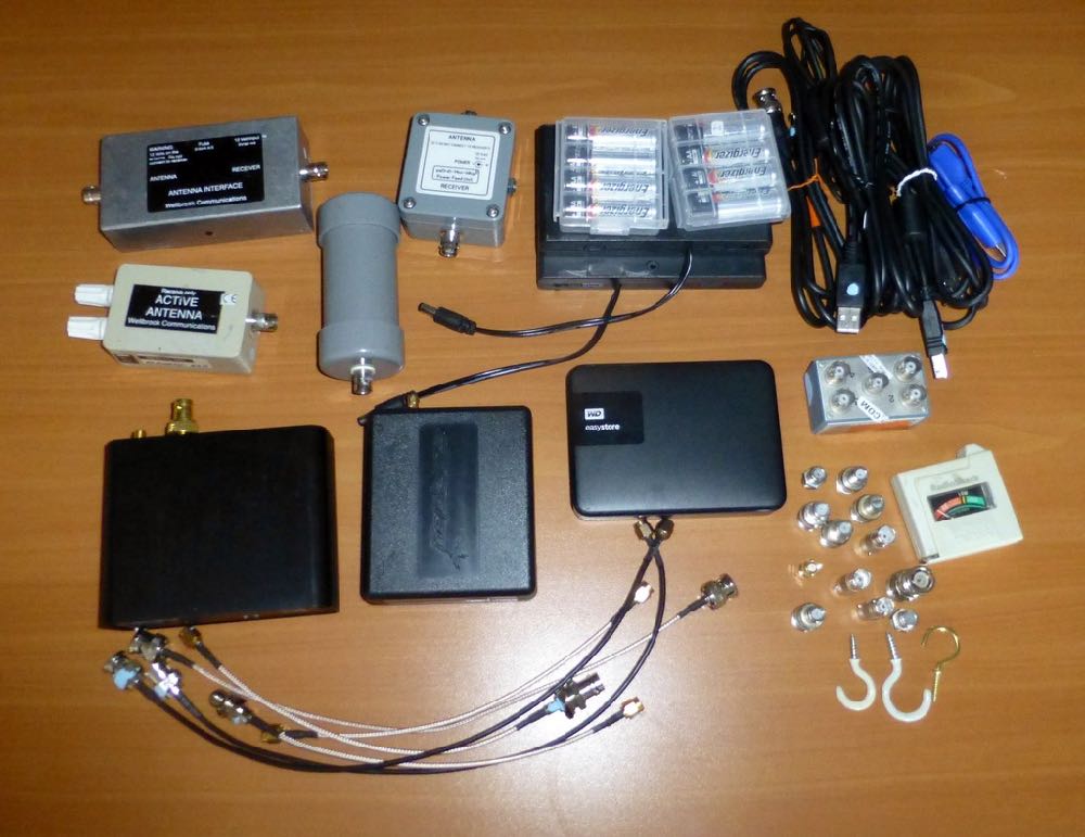
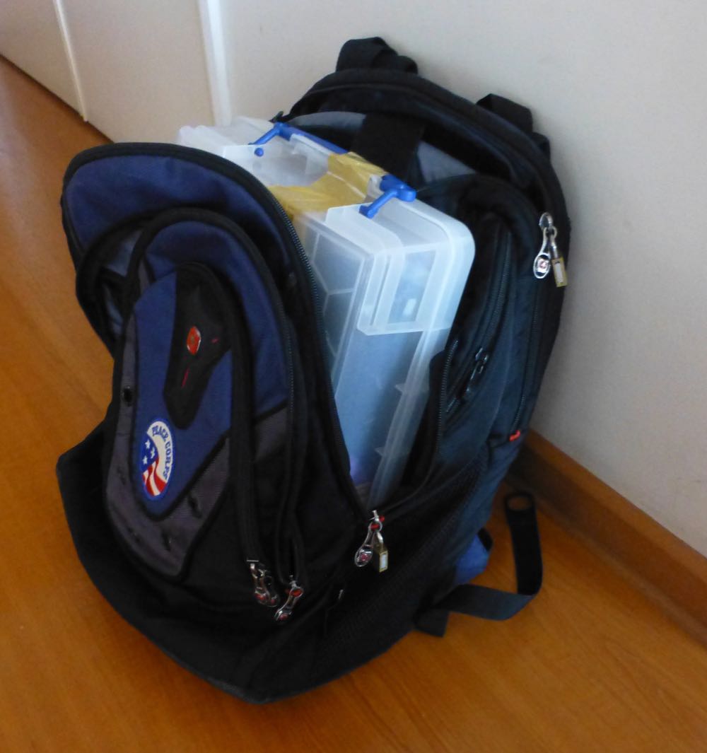
The above being said, here’s a pic of the MSI.SDR unit with the included stuff:
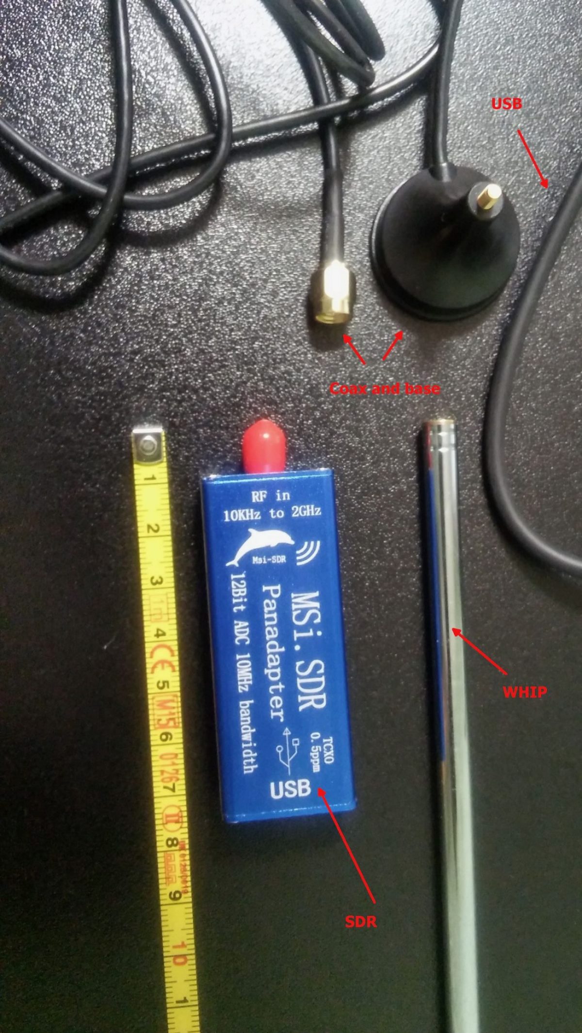
The unit is very small and the box has two connectors, an SMA for the antenna and a micro-USB (like the ones used in cellphones) for the USB cable which is used to both power and control it; the other bits are the telescopic whip antenna (around 98cm fully extended) with a magnetic base and a short run of coax, and the USB cable.
Once I got the SDR I decided to give the included whip antenna a try… well, to be clear, while it will allow you to pick up some strong local FM stations and maybe a bit else, it will only be useful to test if the SDR unit is working (before putting together our antenna), so don’t expect to receive much with that whip, yet… don’t throw it away, it may become useful (more later).
The other important piece is the BalUn. I picked a NooElec “Nine to One” v2, since I’ve used their v1 model and I’ve found it to work well, I decided to pick the newest model which has a better antenna wire connector. The BalUn, which is in effect a so-called “transformer balun” is really small and the junction box I bought is much bigger, but it isn’t a problem. All in all, the box may host a preamplifier in the future, but for the moment it’s fine for the balun. The following pic shows the balun “installed” inside the junction box:
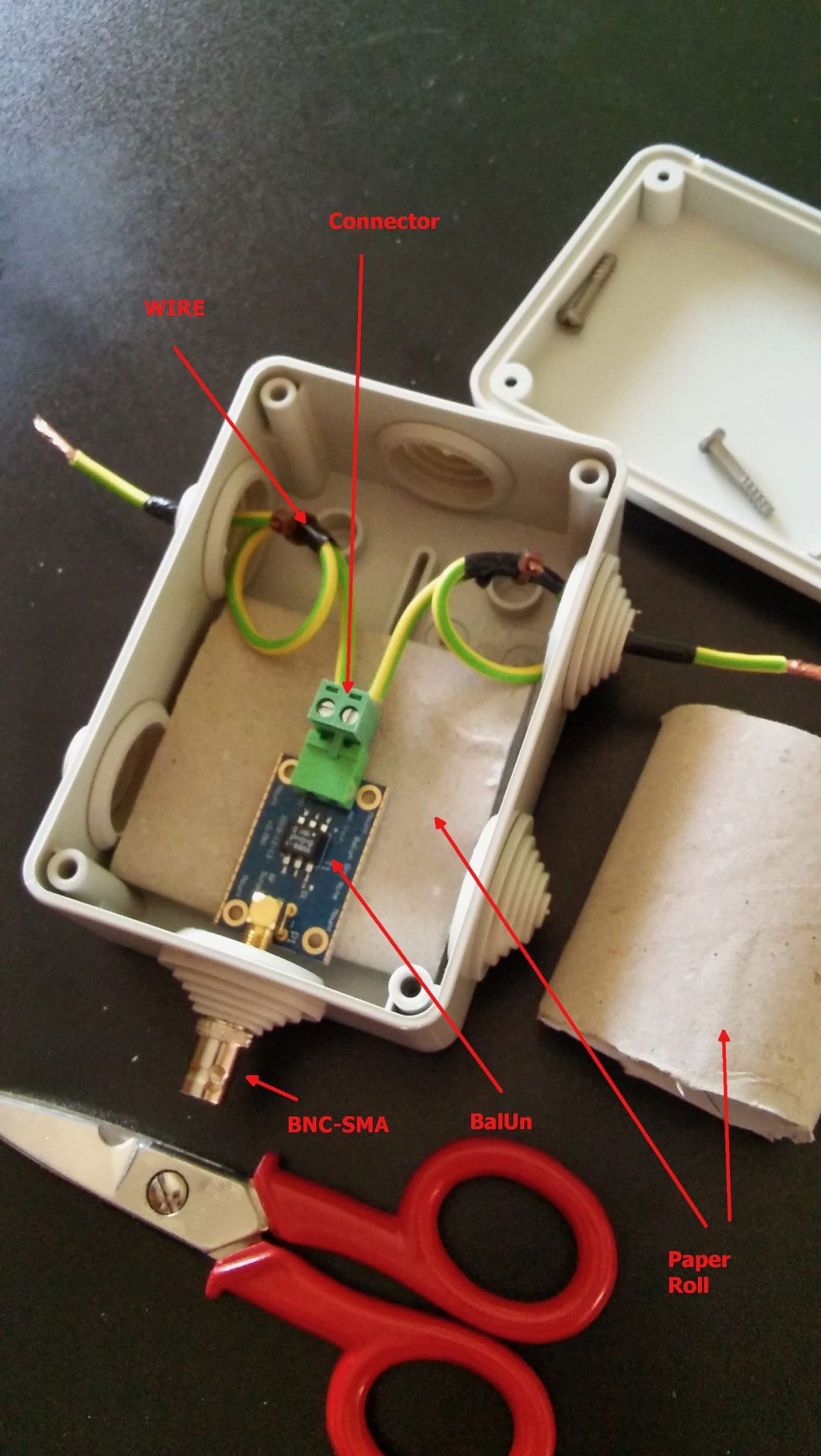
The scissors are there to give you an idea of the sizes; to put together the whole thing, I started by preparing two pieces of wire (the 2.5mm one), made a turn with each wire and locked them with a nylon cable tier. Those turns will prevent the wire from sliding out and putting a strain on the balun connector. I did that since I didn’t have plastic washers at hand, otherwise you may just slide two plastic washers (or proper diameter) over the wires and use two nylon tiers to lock them. In either case, the idea is that the “loops” or the washers won’t slide through the box holes and will support that (little bit of) strain caused by the wire connection.
Next, I stripped some of the insulation from the ends and connected the wires to one of the balun connectors (I chose the one in the pic since I believe it’s the most suitable for this setup), at that point I continued cutting the smaller “ring” of the box insulation caps (the two at top and the bottom one). Then I placed a piece of carboard roll (from a kitchen-paper roll) at the bottom to serve as a support (you can see it below the balun). At that point, I slid the balun SMA connector through the bottom hole and used the SMA to BNC adapter to hold it, done so I slid the two wires (connected to the green wire connector) through the side hole and then inserted the connector into the balun. I then placed the other piece of paper roll above the balun and closed the box with its cap. As a note, to properly close it, start by inserting the screw into the cap holes till end, so that they’ll extrude from the bottom, then place the cap over the box and tighten the screws–you may need to use some force to properly tighten it.
Notice that the wire shown in the pic are SHORT, later on I replaced them with longer wires (outside the box) to be able to better connect the balun box to the antenna, but the remainder of the build is the same.
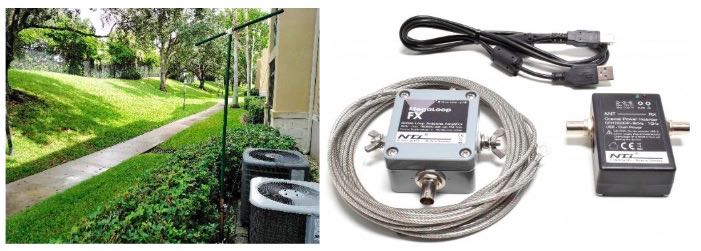
Now that I had my “balun box” ready, I measured the antenna wire and, using the paracord and some nylon tiers, I installed it. I also installed the “counterpoise” wire. For the latter, at first I tried just connecting the remainder of wire to the “gnd” of the balun, leaving the spool laying on the floor, but later on I decided to hang up the counterpoise and the final result was the following:
Click to enlarge
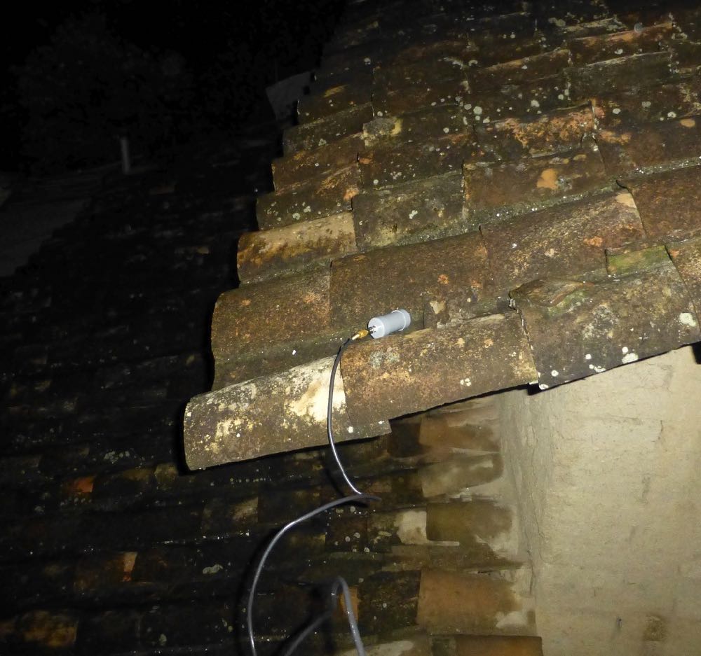
Not a work of art, but then since I was experimenting, I decided not to add PTFE and tape to allow me to quickly rearrange the antenna to run other configurations, yet, the whole setup worked quite well and stood fine to some wind and rain, the picture below shows the balun box with the antenna/counterpoise wires and the coax with the snap-on ferrite chokes.
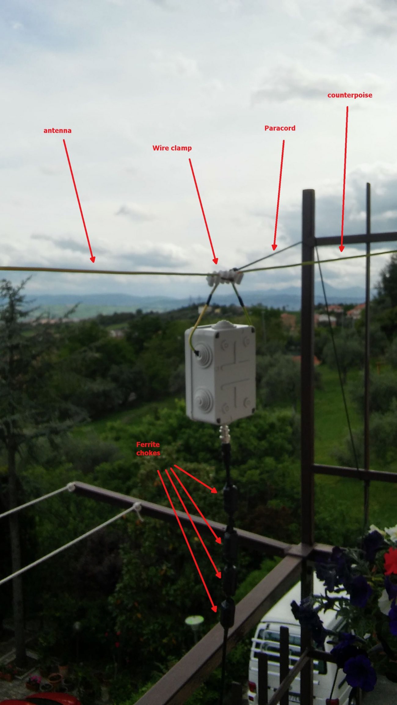
Click to enlarge
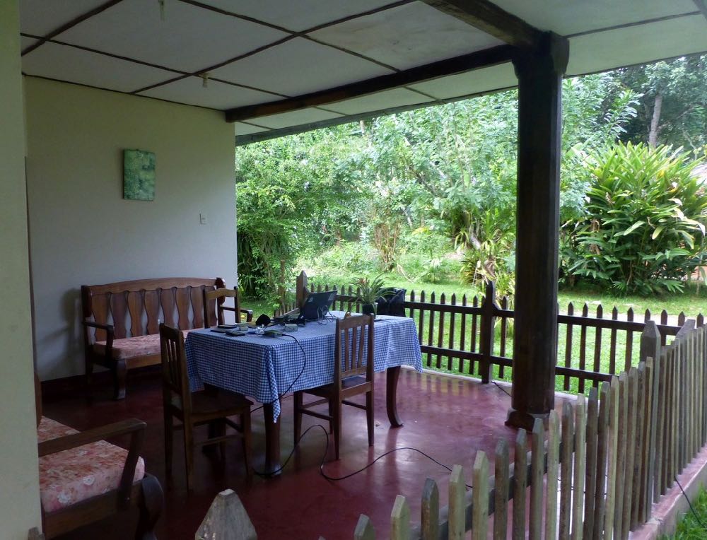
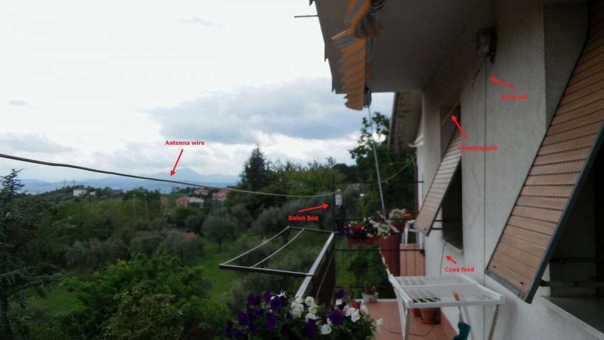
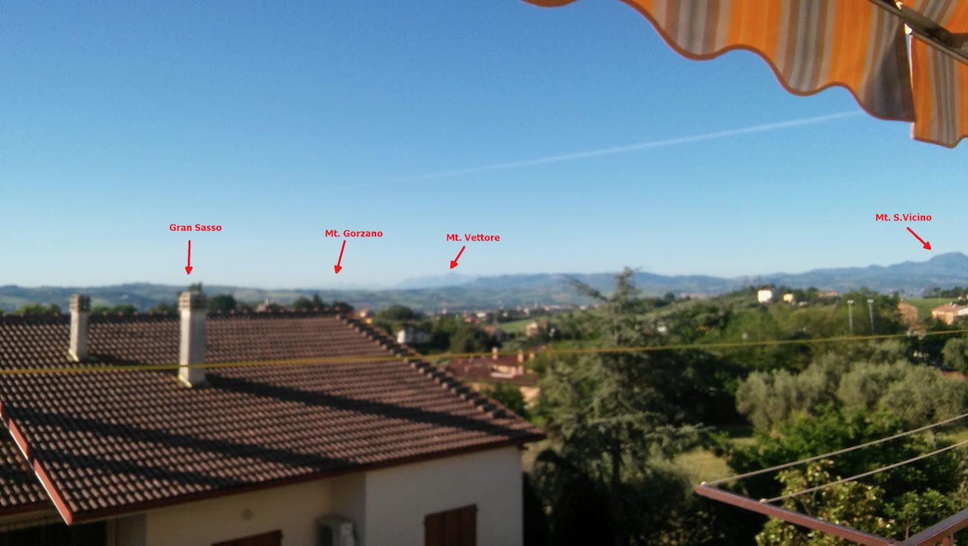
Notice that to avoid putting strain on the balun wires, I used a wire clamp I had in my junkbox–the clamp is then tied to the paracord using a nylon tier and the paracord holds the assembly and keeps the antenna wire in position. The ferrite chokes aren’t properly seated, and I’m planning to remove and re-place them, but for the moment they’re okay. The balcony faces to south/south-west so the antenna has a free horizon of about 270 degrees ranging from the Adriatic coast to the Appennines (Mt. S.Vicino can be seen behind the paracord)–not bad. Here’s another pic showing the horizon to West, just to give you an idea:
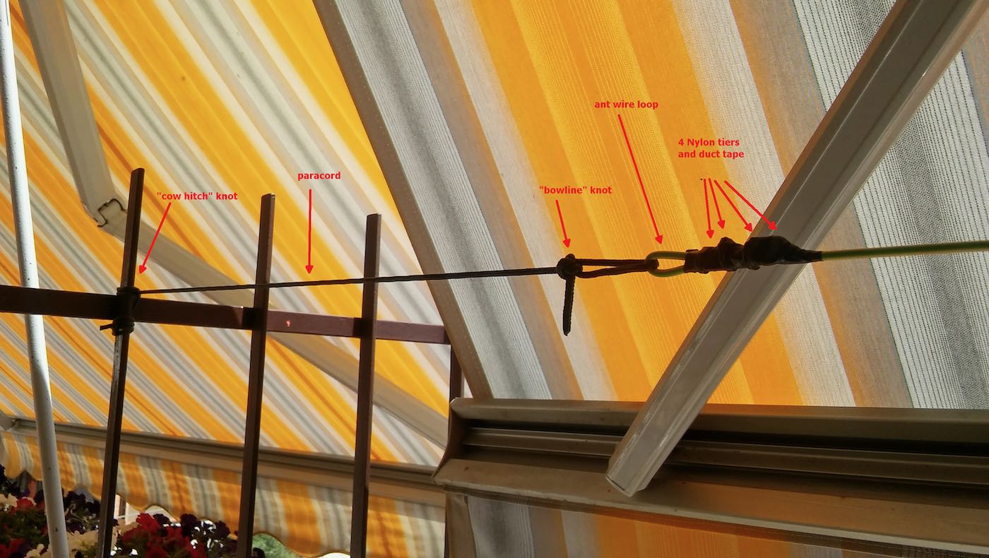
Getting back to the antenna installation, the other end of the antenna wire is tied to the opposite side of the balcony as shown below (let aside the tent/awning, I raise them when using the SDR, also, the bowline knot isn’t correct, I’ll need to tie that again):
The counterpoise instead is supported by a lamp I’ve on the terrace, here’s it’s setup:
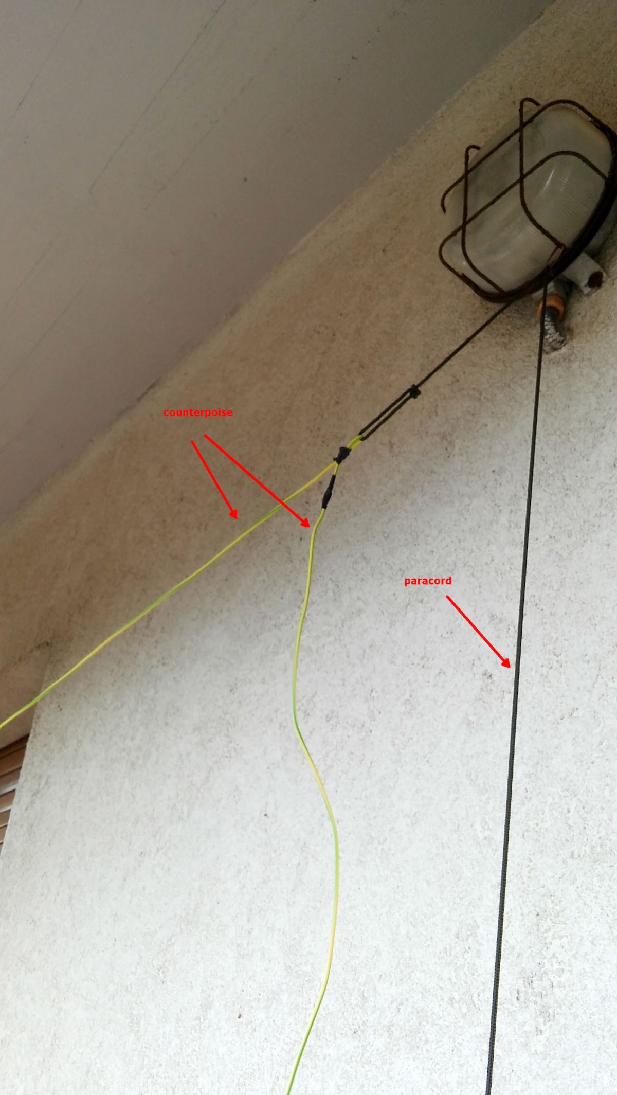
The “paracord” goes down to a plastic bottle filled with a water/chlorine mixture which serves to keep it in place. The remainder of the wire is just hanging down for about 1.5 meters (the counterpoise is shorter than the antenna wire, it’s about 2/3 of its length).
Ok, time to put the antenna and SDR to test, so I brought the coax inside home, connected the other SMA to BNC adapter to the SDR and connected the coax going to the antenna. Note that 15 meters of coax is enough for me, but if one wants a length of up to 25 mt, it won’t be a problem.
I already installed the SDR software, in my case since the unit identifies itself as an “SDR1” I downloaded the SDRPlay “SDRuno” software https://sdrplay.com/windl2.php and since I was at it I also downloaded the PDF manual https://www.sdrplay.com/downloads/ and the “CookBook” http://www.nn4f.com/SDRuno-cookbook.pdf and I heartly recommend reading and digesting them before starting the whole thing (while you wait for all the stuff to be delivered). An important note is that you MUST install the SDRuno software BEFORE connecting the SDR since that way, the SDRuno setup will install the proper drivers and you won’t have issues.
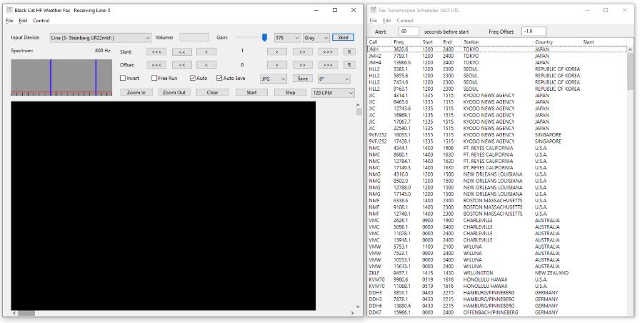
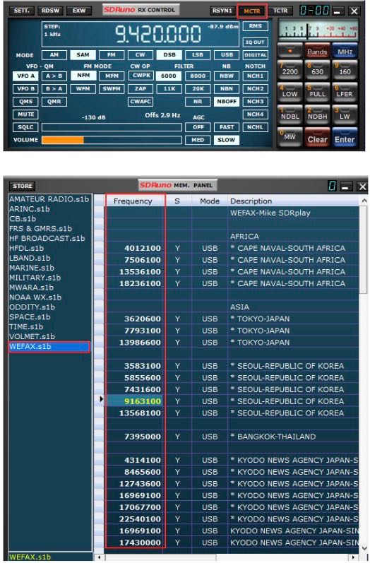
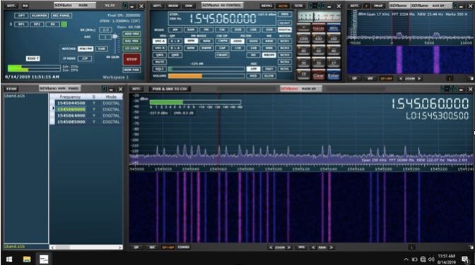
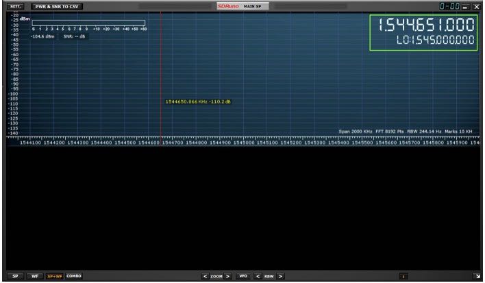
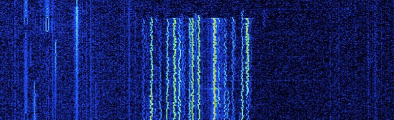
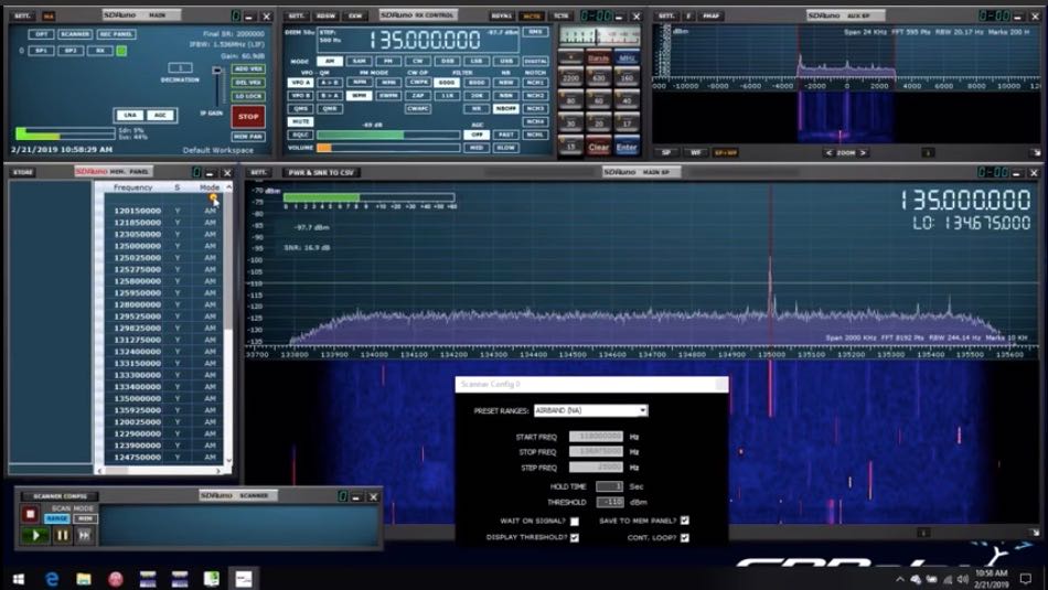
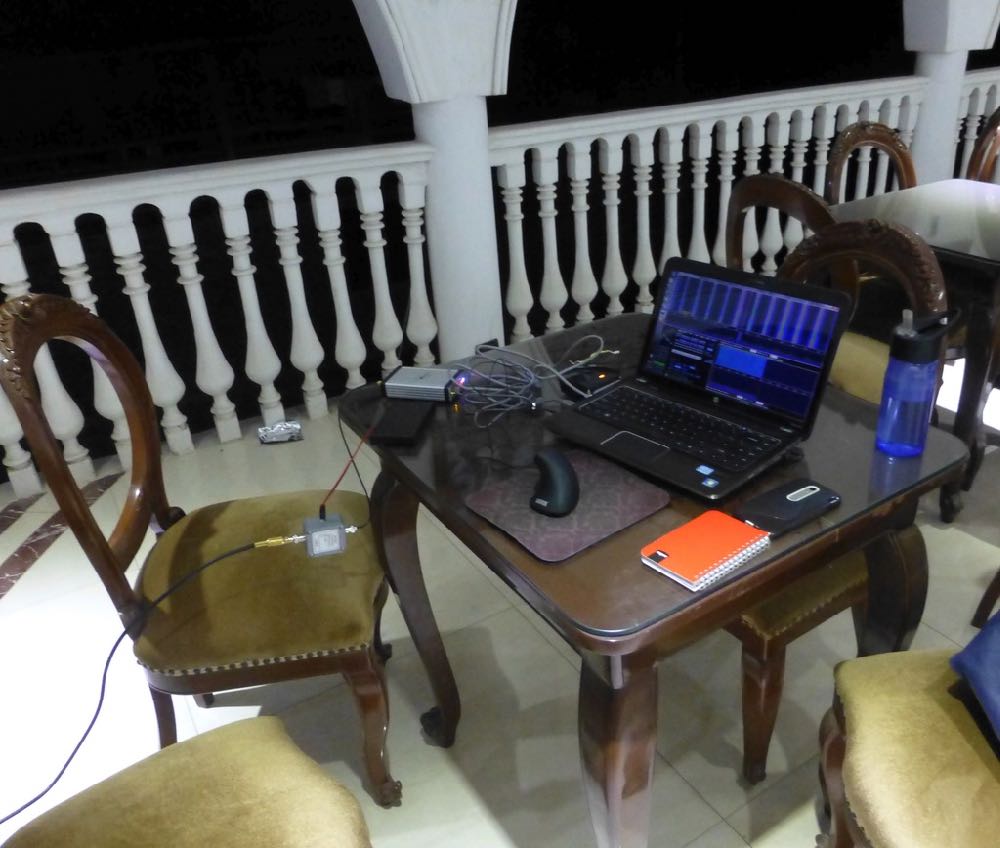
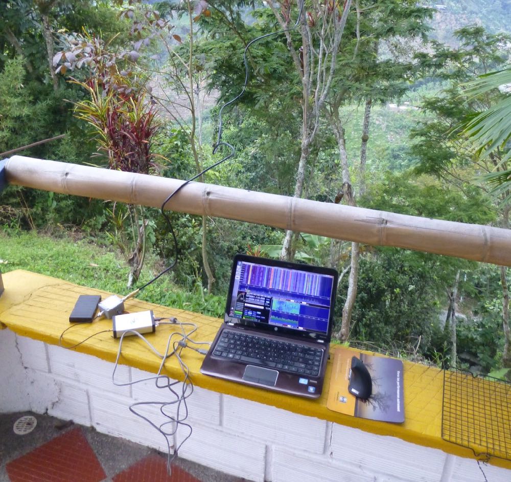
Anyhow, I connected the coax to the SDR and then it was time to fire up the whole thing and give it a spin; so I powered up the laptop (technically, a “transformable” laptop/tablet), started SDRuno, opened the “RX control” and “Main Spectrum” windows and then clicked the “play” button, clicked the “broadcast” band, and the “MW” one and got this:
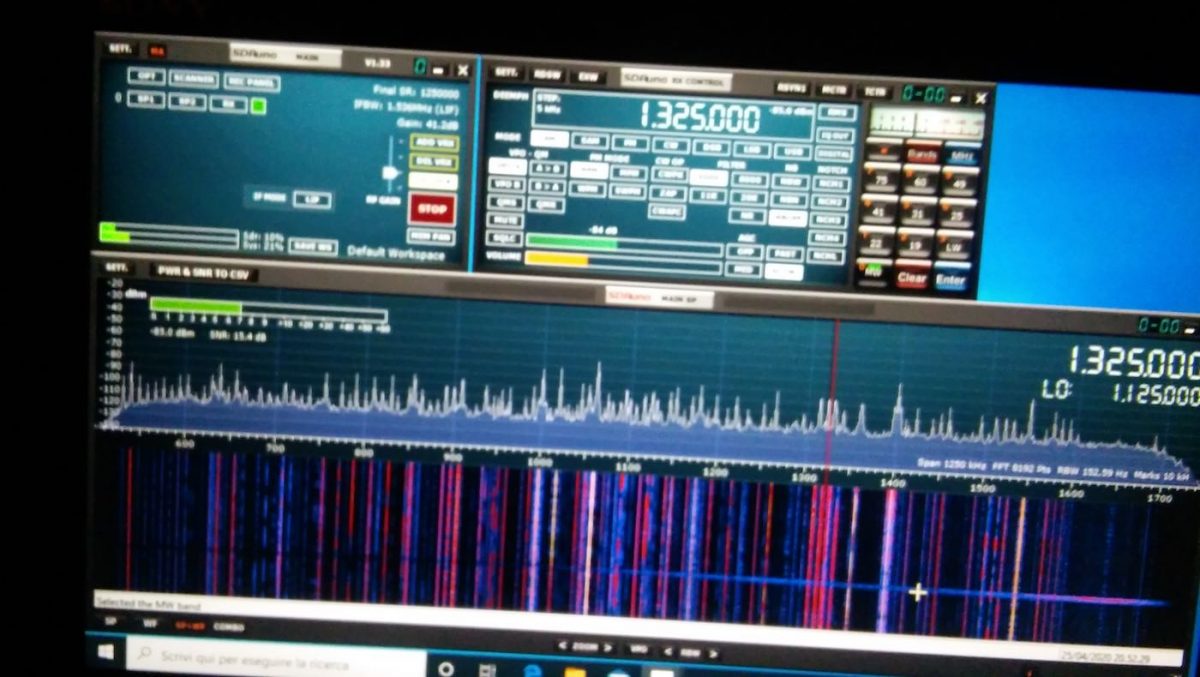
Not exceptional maybe, but not bad, either; in particular if one considers that it’s from a quite short piece of wire which isn’t exactly placed in an ideal position.

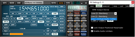
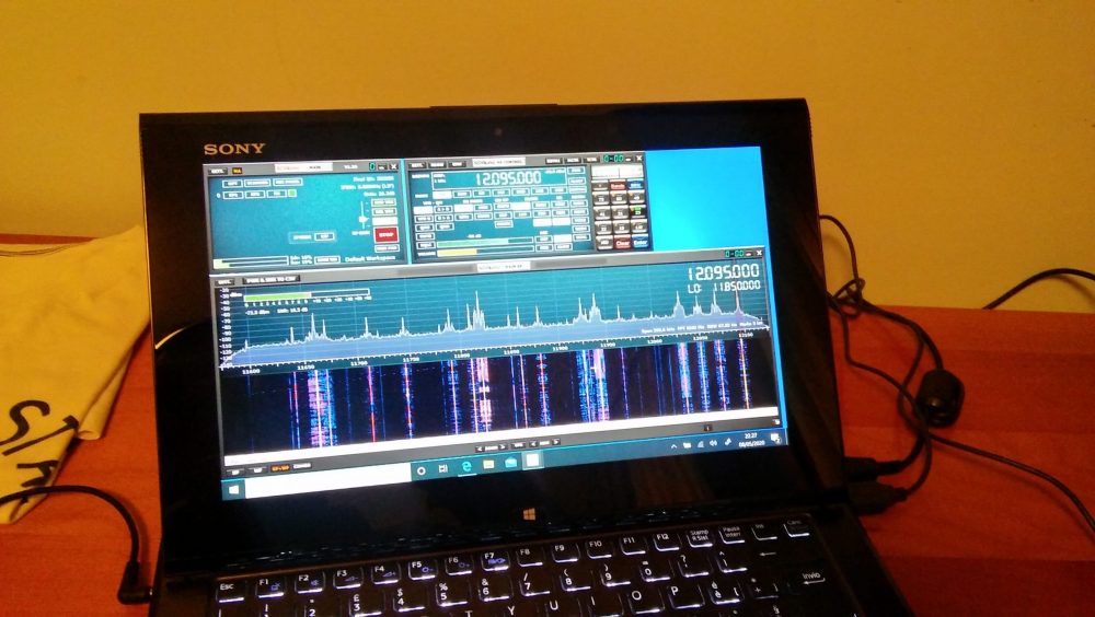
Deutsche Welle
So I went on and explored the bands a bit. On ham bands the SDR picked up signals from the whole mediterranean basin (Cyprus, Lebanon, Spain and then some) and from north too (Russia, Germany, Denmark); then depending on time, I was able to clearly receive broadcasts from China, South America, Africa and more ham QSOs from a lot of places.
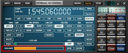
BBC Ascension Island 5/9+ and just a bit of QSB
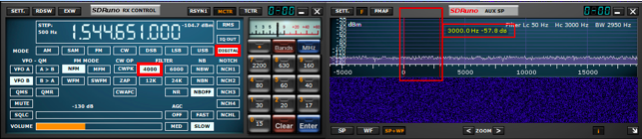
I must admit I didn’ record the callsigns or stations identifiers (“guilty” your honor–!) but I was more focused on testing the SDR and antenna than running a “DX session” at any rate. On the BCB bands I picked up WWV, BBC, VoA, China Radio International, Radio Free Asia, Radio Romania and a bunch of others from Middle East, Asia, Africa and South America. While on the ham bands, I was able to pick up some quite interesting QSOs and then… well, I went hunting for higher frequencies signals!
I got Police, Ambulances, Air control…so even if that “piece of wire” isn’t optimized for VHF/UHF it seems to be working decently there too. By the way, when changing bands you may (and probably will) need to adjust the gain control, but that will be almost the only thing needed to pull in signals
At the end of the day, I can say that I’m quite pleased with the performance offered by this simple and cheap setup. For less than 150 euros you have everything you need, not just the SDR.
Sure, the setup may be improved, but then again you’ll have all of the basic parts, so you won’t need too much. For example, if you live in a really noisy environment, it would be a good idea to use a loop antenna. You would only need a “cross shaped” support (PVC pipes or wood will do). You could quickly put together the SRL (Small Receiving Loop) designed by Matt Roberts (KK5JY) http://www.kk5jy.net/rx-loop/ the balun will be the SAME (yes, no need to wind whatsoever!) so building it will just be a matter of assembling a cross shaped support for the wire (which we already have because it’s the same used for the wire antenna) and you’ll have it. While I already tried the SRL, I didn’t build one to test with this SDR, but I’ll probably do that as soon as SWMBO will start complaining about those “wires on the balcony.”
Also, at the beginning I wrote “more later” when writing about the telescopic whip included with the SDR. Here’s the idea–it requires soldering, so if you don’t want that, skip this: remove the adhesive sheet on the bottom of the antenna base to expose the bottom cap and then remove (extract) the bottom cap. You’ll see a magnetic ring and a “bell shaped” piece of metal (the “ground” for the whip). In the middle of the “bell” there will be the antenna connector which is soldered to the coax wire with a nut holding the connector (and the “bell”) in place. De-solder the coax, unscrew the antenna connector and extract it, at that point you’ll have the telescopic whip and its connector, now you may use them to build the active “whip” antenna described here:
http://www.techlib.com/electronics/antennas.html#Improved%20Active%20Antenna
Notice that it is NOT the “usual” active whip–the circuitry and idea behind it is totally different–yet it works fine and will serve you from VLF (not kidding) up to around 100MHz. It might be a good companion for the SDR. It won’t be as quiet as the loop, yet it may be a valid “all rounder.”
To conclude, I believe that the setup described above is something anyone can afford. You don’t need to be an engineer or to have special knowledge or abilities–it’s just a matter of putting together some bits and pieces.
Obviously, this setup doesn’t require a large space and offers good performance across the bands. Plus it’s so easy to improve since the 12bit SDR is a good starting point
All the best everyone and STAY HOME, STAY SAFE !
Thank you so much, Grayhat!
I love the fact that you invested (however modestly) in a proper antenna setup to better serve you rather than relying on the basic whip antenna that comes with the SDR. You’re right: too often, we invest a receiver, yet invest no money or time into building an appropriate antenna. The antenna is the most important component in a proper radio setup and those included telescoping whip antennas simply don’t perform well on the HF bands.
Based on our correspondence, I know you had fun piecing together this little system using a simple bill of materials and items you had on hand during the Covid-19 quarantine. Thank you for sharing it here with your SWLing Post community!