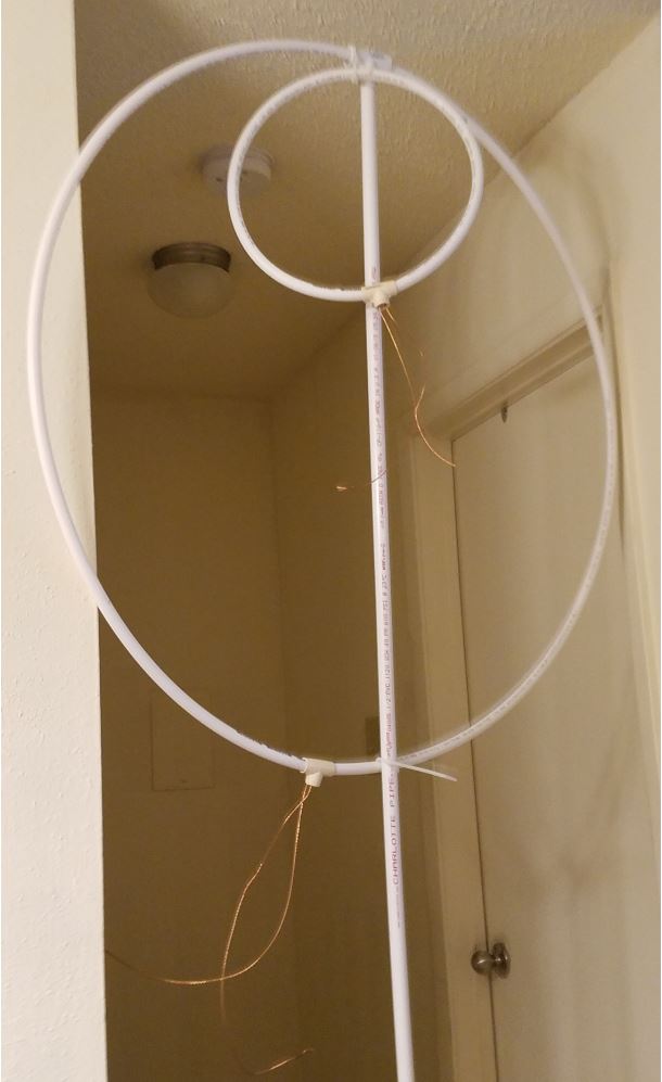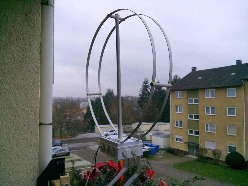
SWLing Post contributor, Klaus Boecker, sports a homebrew magnetic loop antenna on his balcony in Germany.
Many thanks to SWLing Post contributor, Marty, who writes:
I have a question about loop antennas; specifically which type is “better,” passive magnetic loops or active electric loops?
I know, “It depends.”–?
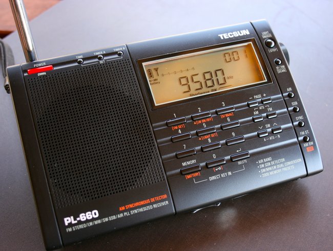
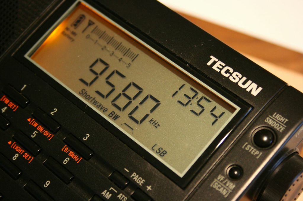
I live in a ground-floor apartment, with a small porch, lots of RFI and restrictions against visible antennas. Also there are no trees within 75 ft of my porch, which faces on a parking lot. My radio is a Tecsun PL-660, which works okay inside with my 10-ft bare wire antenna hidden on the porch.
With a loop antenna, I’d like to mount the antenna on the porch at night and have a remote tuner/control inside because it’s very hot n humid here in Louisiana even after dark.
No doubt there are a number of magnetic loop antennas that could serve you well in your situation, Marty.
To answer your first question, though, you should search for a wideband amplified loop antenna since you’re only concerned with receiving.
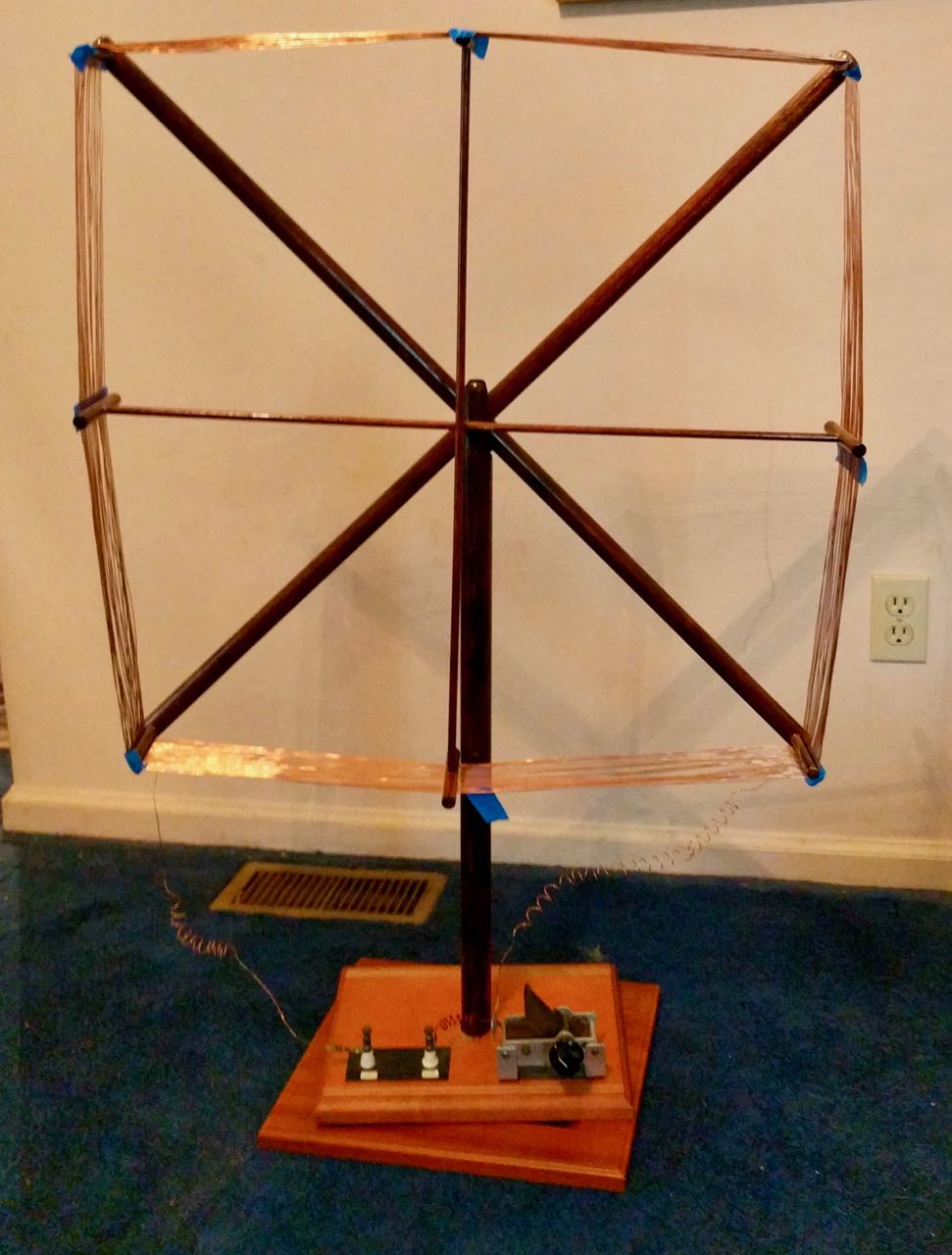
Passive loops are great antennas on the shortwave bands–and easy to build–but they best serve ham radio operators who wish to transmit. Passive loops typically have a very narrow bandwidth that requires the operator to constantly tune the antenna when they tune the radio a few kHz. Most amplified wideband loops need no separate tuning mechanism.
Last year, I posted an article about choosing the right loop antenna for situations like yours where one has limited installation options.
Click here to read : Shortwave antenna options for apartments, flats and condos
Portables and amplified loops?
I do hesitate to encourage you to invest in an amplified loop antenna when your only receiver is a Tecsun PL-660. Some portables don’t handle amplified antennas well–they can easily overload and I imagine you can even damage the front end of the receiver.
I’m well aware, however, that there are a number of readers here who do couple their portable radio to an amplified loop. I have connected a number of portables to large wire antennas and found they could easily handle the extra gain, so I imagine an amplified loop would perform as well; the Sony ICF-SW7600GR, Tecsun S-8800, and Sangean ATS-909X come to mind.
But the PL-660 is a hot little receiver even with the built-in telescopic antenna–I’m not sure if amplification would help or hinder.
Please share your experience
This is where I hope the amazing SWLing Post community can pitch in and help us out here!
Does anyone here regularly connect their PL-660 to an amplified loop antenna? If so, what model of antenna are you using? Are there other portables out there that you regularly connect to amplified loops? Please share your notes, thoughts and experience in the comments section.
Thank you in advance!
Do you enjoy the SWLing Post?
Please consider supporting us via Patreon or our Coffee Fund!
Your support makes articles like this one possible. Thank you!


 Many thanks to SWLing Post contributor, Marty Kraft, who asked that I share the following question with our community: