Shortwave listening and everything radio including reviews, broadcasting, ham radio, field operation, DXing, maker kits, travel, emergency gear, events, and more
Many thanks to SWLing Post contributor, Mark (M7MHY), who shares the following review:
Impressive Pocket Performance!
‘Shirt pocket’ radios are one of my favourite aspects of the hobby. For me, nothing quite beats the enjoyment of cruising the MW band (and a little SWLing on radios that allow), with a tiny, generally inexpensive unit and pushing the boundaries of what is possible with these receivers and their mini-sized internal ferrite bars. I think there should be another subsection of the ultralight category to accommodate such radios – “super ultralight”!
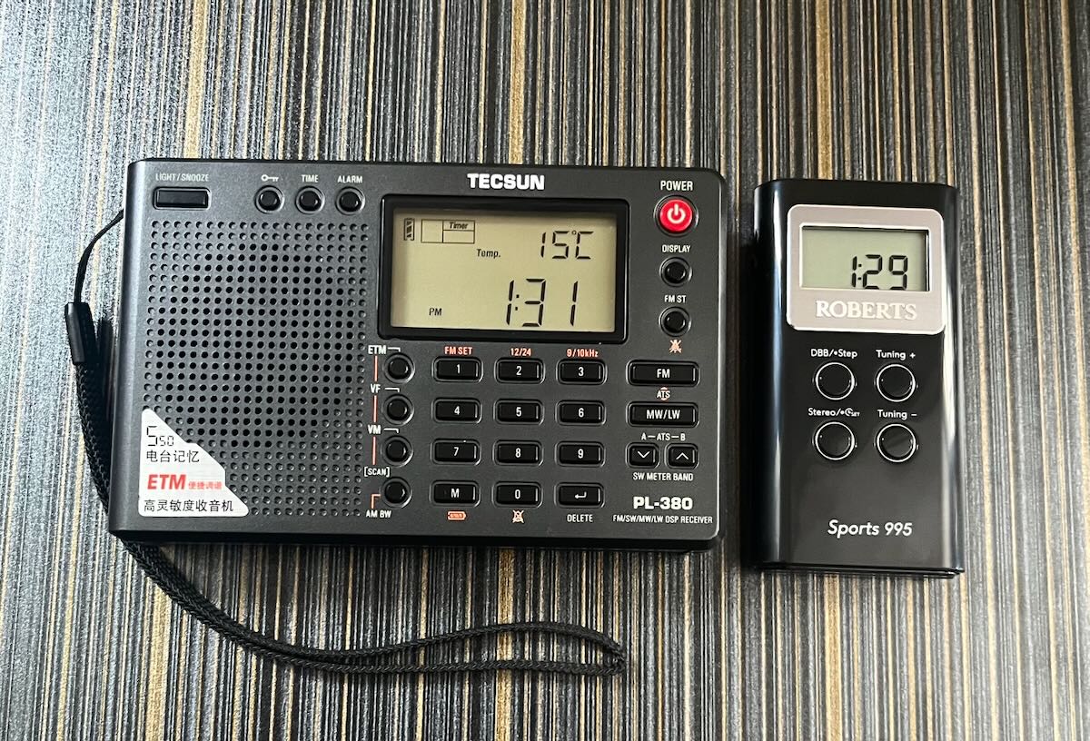
Both radios are of ‘ultralight’ status, but note the size difference.
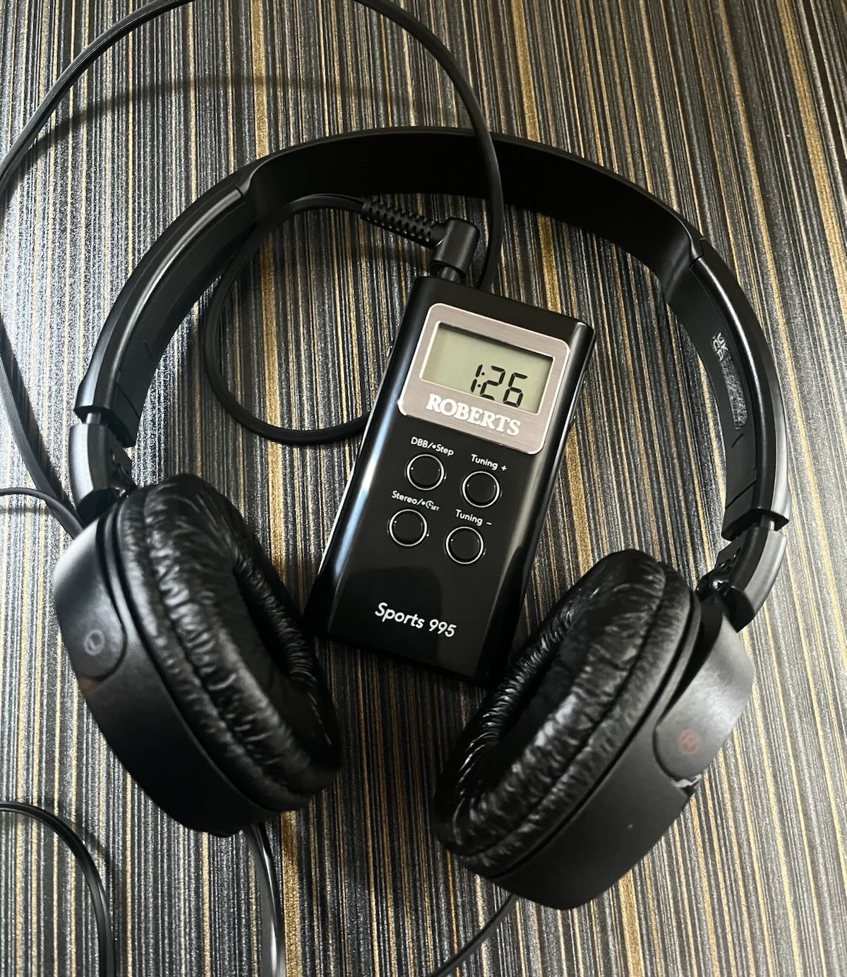
A couple of days ago, the mail arrived and with it, brought another ‘shirt pocket’ radio for my ever-growing collection – a Roberts Sports 995, which I believe to be a rebadged Sangean DT-120 for the UK market.
Two AAA batteries brought it to life, and a quick glance at the manual told me how to set the clock. I plugged in my headphones and confirmed all was working before waiting patiently for the dark hours to arrive.
I live in a rural location just outside of Edinburgh, Scotland and my band scan was done indoors ‘barefoot’ – with no passive MW loops or suchlike, anywhere in sight.
I settled in with the new radio around 12:30 am and began to scan the medium wave frequencies.
I have omitted the strong daytime stations from this list. Here are my results;
648 kHz – Radio Caroline, Orford Ness, Suffolk, 4kW
327 miles
882kHz – BBC Radio Wales, Washford, Somerset, 10kW
324 miles
972kHz – Sunrise Radio, Southall, London, 1.6kW
323 miles
999kHz – Cadena COPE, Madrid, Spain, 50kW
1067 miles
1035kHz – Lyca Gold, Southall, London, 2.5kW
323 miles
1116kHz – BBC Radio Derby, Burnaston Lane, Derby, 1kW
217 miles
1170kHz – unable to ID foreign station
1260kHz – unable to ID foreign station
1296kHz – Radio XL, Birmingham, 10kW
239 miles
1305kHz – Premier Christian Radio, Chingford, London, 0.5kW
322 miles
1368kHz – Manx Radio, Foxdale, Isle of Man, 20kW
129 miles
1386kHz – Radio Baltic Waves International, Viesintos, Lithuania, 75kW
1093 miles
1458kHz – BBC Asian Network, Birmingham, 5kW
239 miles
1467 kHz – TWR Europe, Roumoules, France, 1000 kW
930 miles
1557kHz – Radio Letna, Kaunas, Lithuania, 50kW
1064 miles
1602kHz – unable to ID foreign station
I am fortunate enough to own a number of this style of radio, and this is without doubt the best performance I’ve experienced with one of these. The Roberts Sports 995 truly is, in my opinion, a tiny DX machine, which will only improve further with an MW loop. I know of no better performing “super ultralight” in this price category (RRP £39.99). It is well worth considering if you happen to enjoy this area of the radio hobby as much as I do.
Many thanks to SWLing Post contributor, Bob Colegrove, who shares the following:
A Rack of Radios
by Bob Colegrove
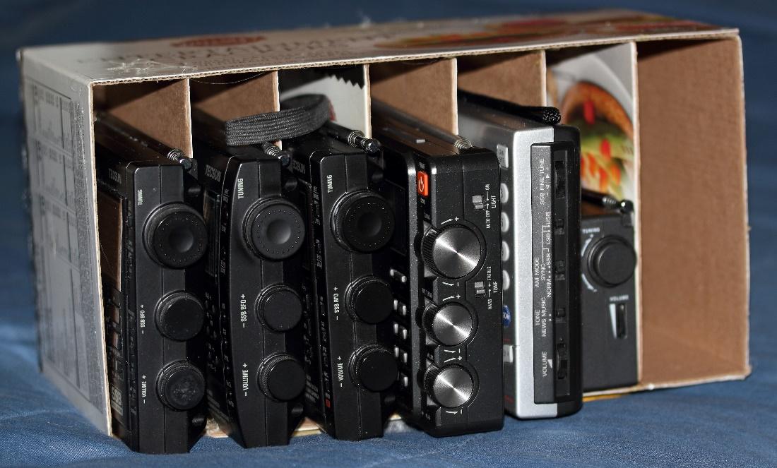
You simply cannot have enough radios – a principle I learned a long time ago. The difficulty occurs when it comes to storing them and yet having them at the ready when necessity calls. Turns out several of my portables fall within a dimensional range that they can be conveniently stored in a rack on the table.
I would like to say I made a project out of this choosing a fine hard wood for construction, carefully routing each divider into a finely milled slot, tastefully finishing the whole thing off with appropriate stain and varnish, and perhaps lining each slot with felt of finest virgin wool. However, never having been one to let form triumph over function, instead, I found a couple empty cracker boxes of the right dimensions, made a few cuts with a hobby knife, and applied some hot glue. Whalla!
Wait a minute. Is that an unused slot at the end? Hmm!
I love it, Bob!
I mean, you know those cracker boxes just wanted to become a custom radio rack–! I say save the fine wood working to build the shelf upon which you’ll place your bespoke cracker box radio rack.
Many thanks to SWLing Post contributor, Julian S, who shares the following guest post and review:
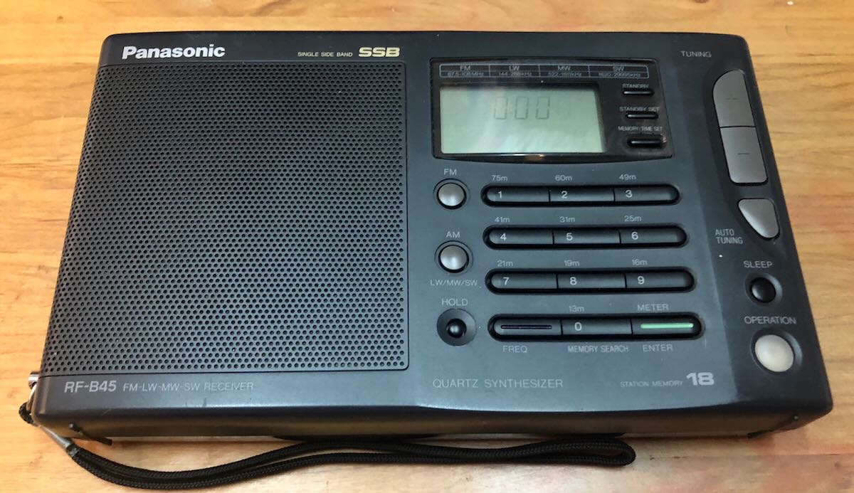
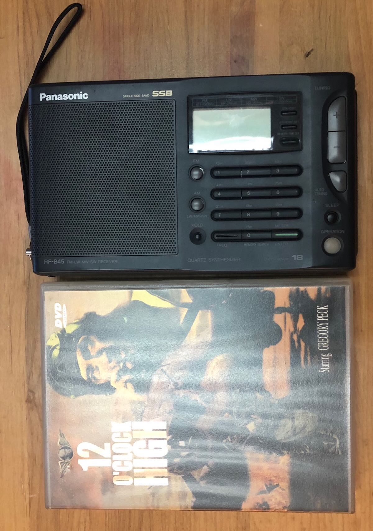
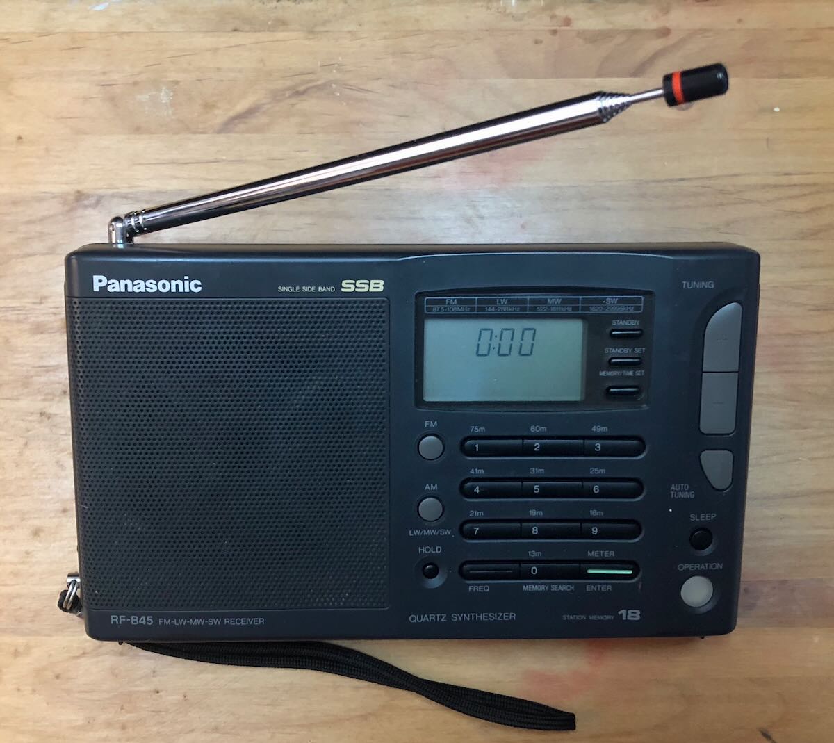
Panasonic RF-B45 – A Comparative Review
by Julian S
18 and 19 October, 2022
I was raised on valve / tube radios. From my pre-teens in the 1960s, I enjoyed tuning through the frequencies as a form of exploration. In the 1970s I experimented with antennae to improve reception. And later, starting in the 1980s, I began to use travel radios, always looking for that perfect radio.
Today the perfect radio for us SWL’ers might need to include a time machine to take us back to the halcyon days of SW, say in the 1980s or 1990s, before so many Western broadcasters axed their Short Wave services.
Looking at the BBC World Service’s latest round of cuts, I am filled with horror. Is whoever decided those cuts deeply cynical or deeply ignorant?
Switching BBC World Service content from radio to the internet for countries that block or restrict internet access is not the way to reach people living there. In places where every person’s internet access is monitored, where access to websites and web-content is censored or blocked, BBC news internet content will not be widely available. Today and for the foreseeable future the way to reach perhaps half or more of the world’s population is radio, especially Short Wave radio broadcasts.
The People’s Republic of China (PRC) and other like-minded countries, eg the DPRK (North Korea) fully understand the importance of radio, especially Short Wave and they vigorously maintain multiple Short Wave broadcast programmes as a way to project soft power and influence people.
In this context, it’s no surprise that when the Australian Broadcasting Corporation in 2017 suddenly, unexpectedly and against a back-drop of protests from Pacific Island Nations and rural Australians ditched its Short Wave broadcasts, the PRC’s China Radio International grabbed Australia’s SW frequencies.
I heard that in an earlier round of cuts China acquired frequencies dropped by the BBC World Service.
By the time the West wakes up again to the importance of Short Wave radio broadcasting as a means to communicate to the world, they will find the SW airwaves are full of PRC, North Korean, Vietnamese, Cuban and other broadcasters who never forgot how important SW broadcasts to the world are. I’m reminded of a line from the Sean Connery film, Rising Sun, “If you don’t want us to buy it, don’t sell it.”
Aside from the broadcasters mentioned above, there are still many others broadcasting on SW and there are plenty of Hams too. Short Wave radio listening and Ham radio are widespread and popular in Asia and Africa and are a major source of news. In some countries SW is also used as a means of business and social communication. So much so that there are home-grown radio and transceiver manufacturers in a number of African and Asian nations.
SW listening is big in China. So it’s no surprise that probably the best manufacturer of consumer grade short wave radio receivers is a China based company, Tecsun, who need no introduction. Tecsun seems to have taken over the role that was once held by Grundig, Sony, Panasonic and others. Indeed many of the later Grundig models are made by Tecsun.
If you’ve guessed that I like short wave radio, you’ve guessed right. And I suppose like many other fans, I usually have my eye open for something special.
Since hearing of the Panasonic RF B65 some years ago, I’ve been on the look-out for one at a reasonable price… this search led me to the RF B45…. But I’m a man of modest means so I need them to be priced accordingly.
Usually these two 30+ year old radios are priced on North American eBay like holy grail radios. More expensive than a 2nd hand Sony ICF 2010 / 2001D. Go figure. But the other day I found a Panasonic RF B45 for what I considered a reasonable price. It arrived yesterday, well packed, clean and in good condition. After dinner and this morning before breakfast I put it through some of its paces
What follows are some initial impressions of the Panasonic RF B45:
I’ve read a few reviews of it on eham, shortwave.ch etc. The controls are pretty easy to figure out. It has a similar form factor to the Sony ICF7600 series and is probably comparable in performance to the digital iterations of the Sony 7600 series… though the only 7600 series radio I have at present is the analogue 7601 which is comparable to the Tecsun R9700DX, except in price. New the Tecsun R9700DX is likely to be cheaper than a used Sony 7601 on eBay, and the Tecsun has a wider range of features, eg external antenna socket, comes with a long wire antenna, has better audio… but I digress…
…back to the Panasonic RF B45. This is a fine compact travel radio about the size of a paperback book or two DVD stacked boxes. Continue reading →
I’m not sure why, but near the end of the year I always like to look back at my radio routine and figure out which radios I used the most. Often, the answer is surprising.
This year, I realized there was a very clear winner…
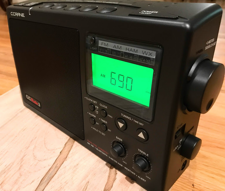
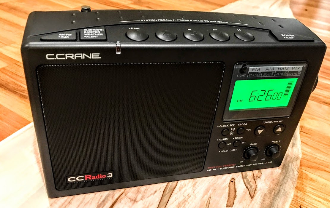
The C.Crane CCRadio3
The C.Crane CCRadio3 has taken lead position as my daily driver. I have it turned on most days for as much as 4-5 hours at a time depending on how much I’m at home.
Here’s why it has become my daily driver:
Benchmark AM/FM reception: The CCRadio3 grabs a solid lock on my favorite local and regional MW and FM stations. At the end of the day, my favorite news program (Marketplace) is available on a local WCQS and distant WFAE. The CCRadio3 can lock onto both equally well. I’ve very few portables that can do this. In addition, I use the CCradio3 for casual MW DXing when I’m not using the Panny RF-2200 or my Chuck Rippel-restored SRII.
Audio: The audio from its internal speaker is superb for voice content, but also robust enough for music. I love the dedicated Treble/Bass controls. The audio can be turned up to the point that it can be enjoyed throughout our house.
Bluetooth: I listen to a lot of content online and pipe it via Bluetooth from various devices to the CCRadio3. I stream the CBC, FranceInfo, ABC, and/or the BBC most mornings from my laptop. I use Radio Garden on my iPad to explore a world of local radio. I also stream Apple Music from my Mac Mini to the CCRadio3. When I do workouts on my stationary bike, I’ll often listen to both podcasts and music on the CCRadio3 via my iPhone.
Battery life: The battery life on the CCRadio 3 is simply stellar. It takes four D cells which offer up a lot of capacity. There are so few digital display radios today that can quite literally play for a few months on one set of batteries. I invested in a set of EBL D Cells and Charger (this package–affiliate link) and have been super pleased. When in the shack/office, the CCRadio3 is plugged into mains power via the supplied AC adapter. All other times, it runs on rechargeable battery power.
It’s ironic, too, because the CCRadio3 doesn’t cover shortwave which is, without a doubt, my favorite band. Thing is, now that so many of my staple news sources are difficult to reliably get on shortwave in the mornings (oh how I miss Radio Australia) I turn to FM and online sources for news content. I still listen to the BBCWS, RNZ, RRI, and at least a dozen other news programs on shortwave, but due to my schedule, it’s mostly casual listening.
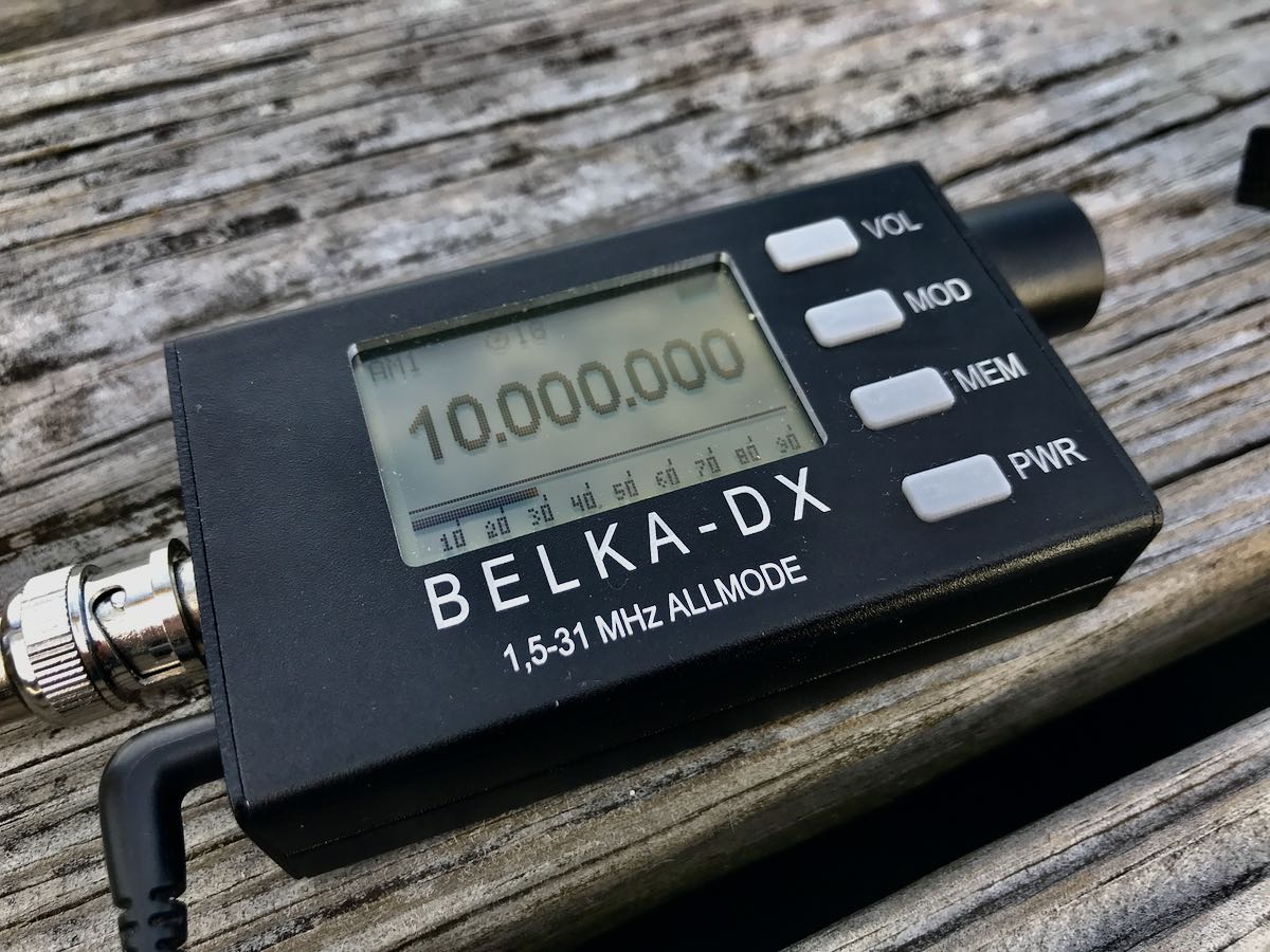
On the go: The Belka-DX
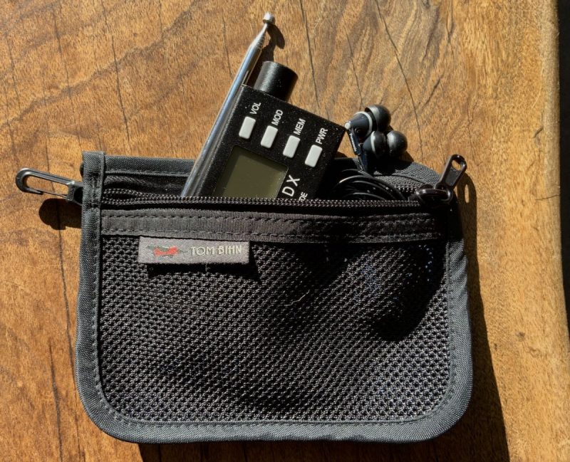
Speaking of shortwave, though, the portable I’ve used the most this year for SWLing has been the Belka-DX. Besides it being a super-performing DX machine, it’s also incredibly compact and portable. I keep it in a small Tom Bihn zippered pouch and it lives in my EDC bag which accompanies me on all errands and travels.
The Belka-DX is so small, I forget it’s there. Even some of my smallest compact portables are nearly three times the size of the Belka-DX.
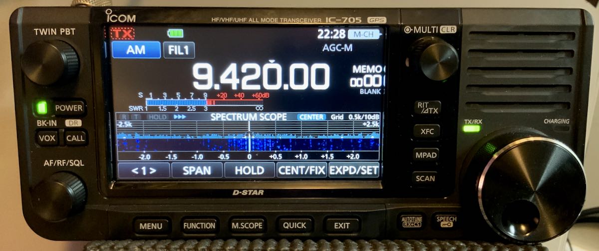
In the field: The Icom IC-705
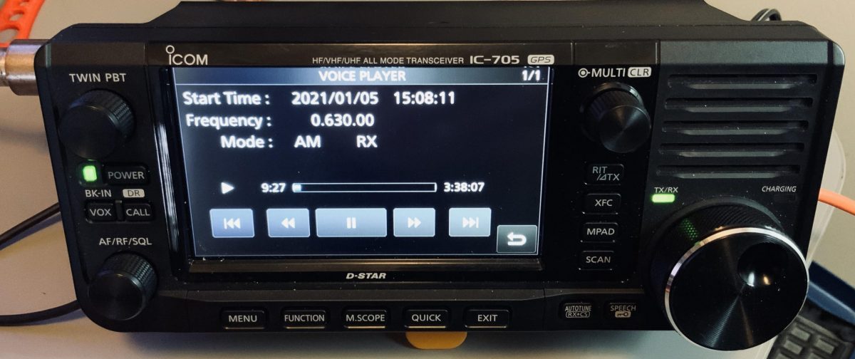
If you follow QRPer.com, you’ll no doubt see that I spend a lot of time in the field doing QRP amateur radio activations of summits and parks. As I’ve pointed out in my review and 13DKA has pointed out in his reviews, the IC-705 is a benchmark shortwave, mediumwave and FM DXing machine. At $1300 US it’s pricey for sure, but it offers up a usable spectrum display/waterfall, audio RX controls, customizable filtering, HF/VHF/UHF coverage, and built-in audio recording/playback.
You don’t even need a 13.8V power supply with the IC-705 as it’ll charge from most any USB source via a Micro USB plug and run in receive for at least 5 hours without needing a recharge. Of course, you could invest in a second, higher-capacity battery pack and get even more battery life.
When I take the IC-705 on a field activation, I’ll often do a little listening after I finish the ham radio portion of my outing. It’s a great reminder of how important it is to take your radios to the field these days. With no QRM, it’s amazing what you can receive.
How about you?
What radios did you use the most in 2021? Please comment!
Many thanks to SWLing Post contributor, Jack Dully, who writes:
I am just wondering what portable receivers are more susceptible to overloading with long dipoles, say 60-70 ft.
I regularly use such and I have never noticed anything unusual happening with a Sony ICF-7600GR, Grundig G3, or PL-880 to name a few. I just ordered a Tecsun 680. Perhaps many of the newer radios have better AGC thresholds or more robust front ends but I really don’t know for sure.
[Also] how exactly do you know if your receiver (portable OR not) is being overloaded by too big of an antenna (ie. dipole, inverted V and the like) and will it damage your receiver? Is there still a way of using a large antenna to capture more distant stations safely, especially with good quality portables?
Thank you for sharing this question, Jack, and my hope is that SWLing Post readers can chime in with details and advice in the comments section of this post.
These are deep topics, but I’ll try to answer a few of your questions…
First of all, you definitely can harm a portable radio by hooking it up to a large antenna. Many portables have no means of protecting themselves from ESD (Electrostatic Discharge). By hooking a portable up to a long wire antenna, you can expose it to ESD which will essentially deafen your radio until you’re able to repair it. Indeed, this reminds me of an article from our archives regarding a Tecsun PL-600 ESD repair. Some radios do have built-in ESD protection (like the PL-680), but I’m not entirely sure it would offer protection from a particularly strong ESD pulse.
Symptoms of overloading can vary. Sometimes overloading can sound like background splatter and even popping. Sometimes you’ll hear “images” of broadcasters across the bands; muffled audio of a blowtorch station. Another sign of overload is when your signal meter jumps at the same time your receiver goes deaf. It’s as if your radio is simply overwhelmed by strong signals and it can manifest itself in odd ways especially since the AGC usually falls apart.
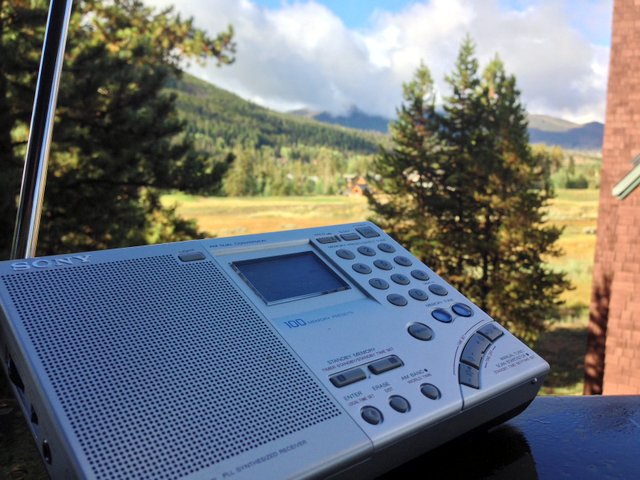
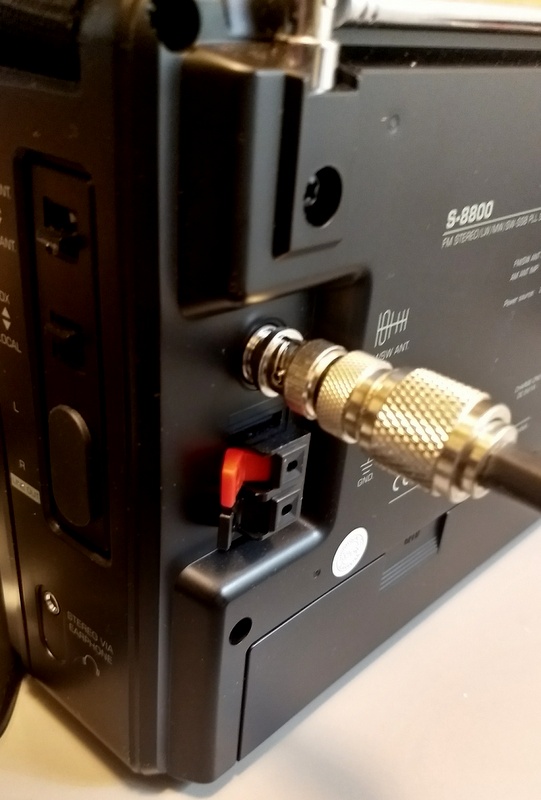
Like you, I’ve found that my Sony ICF-7600GR seems to be able to handle large wire antennas with no discernible overload. Also, the Tecsun S-8800 (above) is well-equipped to handle larger external antennas and even sports a proper antenna port on the back. I know Sangean ATS-909X owners who only use their radio with an external wire antenna and have excellent results.
Some portable radios are very sensitive with the built-in whip antenna, but fall apart if attached to a long wire antenna.
In general, the cheaper the radio, the less likely it has a front end and filtering that can cope with overloading.
Overloading advice?
Please comment with your experience regarding overloading. Have you found some radio models better than others at coping with blowtorch stations, for example? What do you do to protect your receivers from electrostatic discharge when hooked up to large antennas? Please comment!
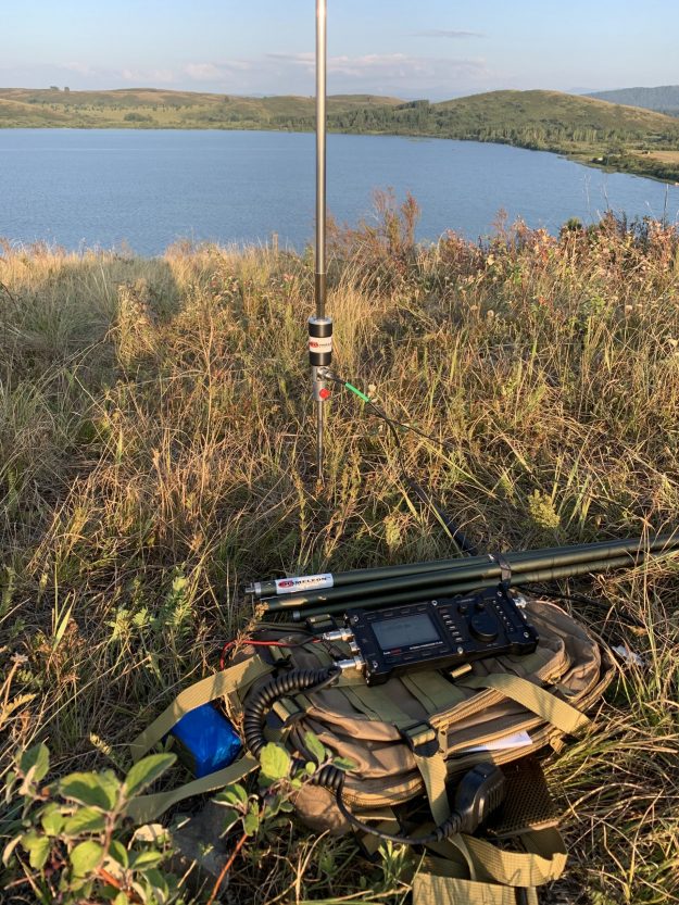
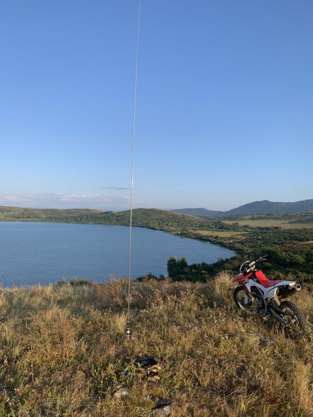
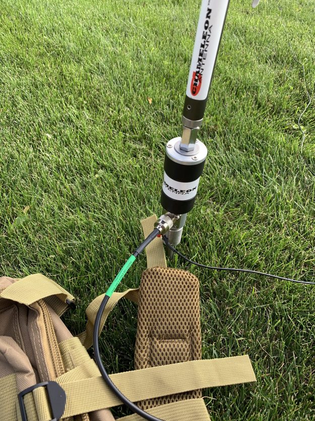
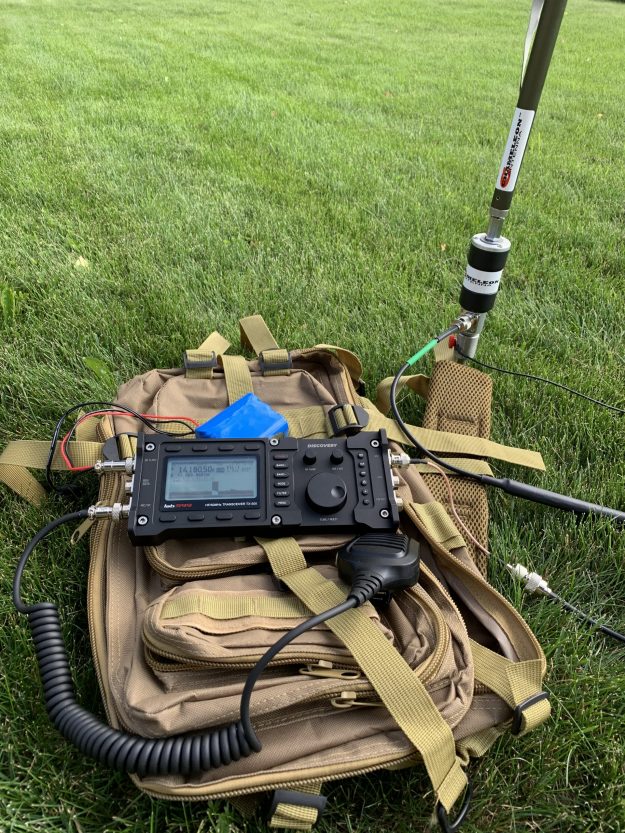
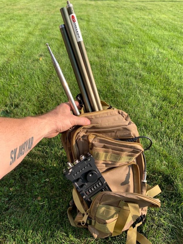
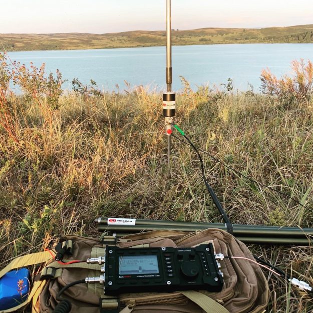
Many thanks to SWLing Post contributor, Don (W7SSB), who shares the following photos of the new lab599 Discovery TX-500. Don notes that all of these photos were taken in Russia–where the TX-500 is manufactured–and include a number of Chameleon resonant field antennas.
Thanks for sharing these, Don. The thin form-factor of the TX-500, paired with a resonant antenna, certainly makes for a lightweight portable field setup!
The following review first appeared in the October 2017 issue of The Spectrum Monitor magazine.
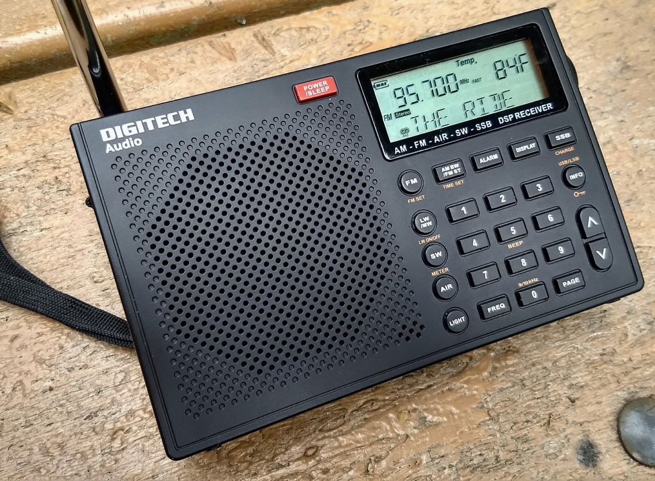
Earlier this year one of my readers in Australia noted the addition of the Digitech AR-1780 to the product offerings of the Australia and New Zealand-based retailer Jaycar.
One thing I’ve learned over the years is that there are few in-country sources of shortwave radios in both Australia and (especially) New Zealand. Jaycar, in a sense, represents what RadioShackand The Source have offered in the US and Canada––a more accessible electronics retailer with some shortwave radio selection.
The Jaycar models are either very cheap sub-$30AUD digital portables, or pricier large portables with a form factor similar to the Grundig S350DL and S450DLX, or the C.Crane CCRadio-SW. The new AR1780 fits somewhere between––a compact portable that promises a compliment of features tailored for the radio enthusiast.
In this review, we’ll take a close look at the AR1780, starting with its feature set.
Features
What appeals to me about the Digitech AR1780 is the amount of features provided by such a compact, traveller-friendly form factor.
Here’s a comprehensive list of the AR1780’s features and specs:
Frequency coverage:
FM 87.5 – 108 MHz
MW 522 – 1620 kHz or 520 – 1710 kHz
SW 1711 – 29,999 kHz
LW 150 – 450 kHz
AIR 118 – 137 MHz
Modes:
FM (including RDS)
AM
Single Sideband
Selectable Bandwidths:
AM mode: 6, 4, 3, 2.5, 2, & 1.81 kHz)
SSB mode: (4, 3, 2.2, 1.2, 1 & 0.5 kHz)
Convenient features:
Sleep timer
Clock/Alarm
Thermometer
Signal strength meter
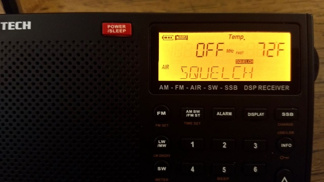
Squelch control
Voice/Music selectable audio filter
Dedicated fine tune control
Headphone jack (3.5 mm)
Key lock button
Key beep on/off
Tuning knob and tuning step up/down buttons
Display button cycles through alarm, time, temperature, and signal strength
FM mono/stereo selection
Backlight button
Selectable 9/10 kHz regional MW tuning steps
Flip-out backstand
Power source: 7 VDC or 4 x AA cells (not included, can be internally charged if NiMH cells)
Antenna: Built-in telescopic and 3.5mm socket for external antenna
Weight: 253g/0.56 lbs (excluding batteries)
Dimensions: 150(W) x 95(H) x 30(D)mm
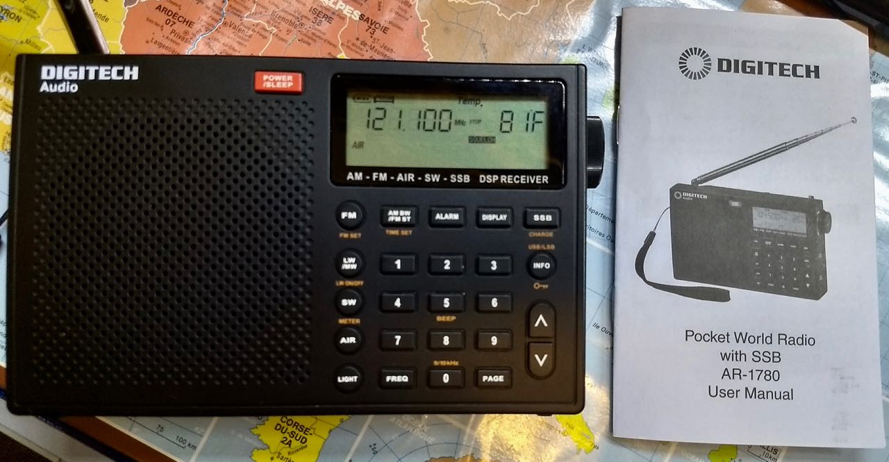
Operation Manual
The Digitech AR1780 ships with a small user manual. In fact, other than the hand strap, the user manual is the only additional item in the box besides the radio itself.
The manual is quite thin––slightly smaller in height and width than the AR1780––and only contains about eight front-and-back mini pages. Although readable, it’s littered with grammatical and punctuation errors. While a manual is certainly a welcome reference item with this feature-packed radio, this manual comes up short, lacking detailed explanations of features and even leaving some out altogether: it does not, for example, offer any explanation on the use of the excellent squelch control, nor does it fully explain the station memory set on multiple memory pages––! Rather unfortunate, as these features deserve a clear explanation.
First impressions
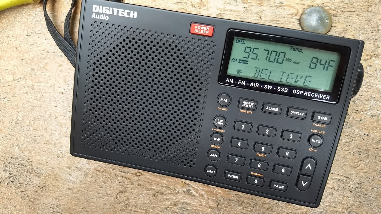
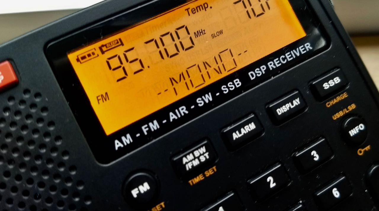
The Digitech AR-1780, like many DSP-based portables, includes a handy temperature display which can be toggled for Celsius or Fahrenheit.
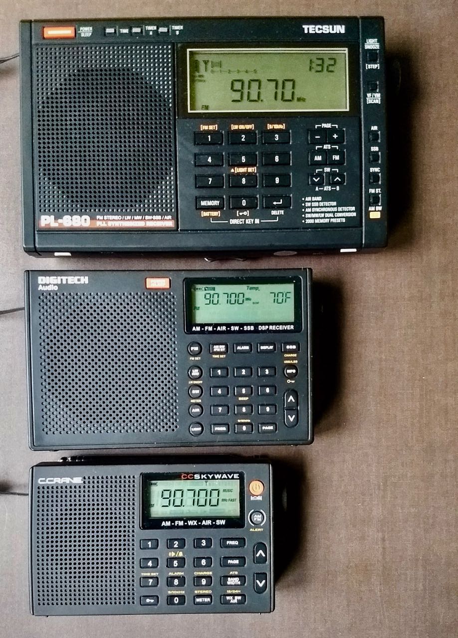
I really appreciate the modest, portable form factor of the AR1780, so it had that going for it before I even opened the box. I travel with portable radios a lot, so the compact body of the AR1780 is very appealing. It’s not as compact as the C. Crane CC Skywave series, or the Grundig G6, but is much smaller than my Tecsun PL-660 and PL-880, or my Sony ICF-SW7600GR.
Comparing size: The Tecsun PL-680 (top), Digitech AR1780 (middle), and the C. Crane CC Skywave (bottom)
Unlike the radios mentioned above, the AR1780 does not include some sort of protective case or bag. I believe this is an omission for a radio aimed squarely at the traveler.
Fortunately, the plastic chassis of the AR1780 feels substantial enough. With the key lock engaged, the only likely problem that could arise from having no protective case is damage to the display, such as scratching.
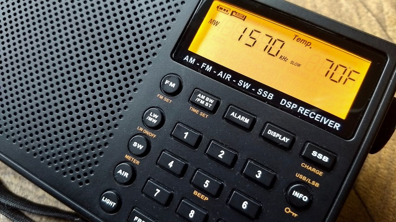
The buttons all have a tactile feedback and seem to respond quickly enough, save powering up the radio, engaging the SSB mode, or changing bands, each of which takes a couple of seconds to engage.
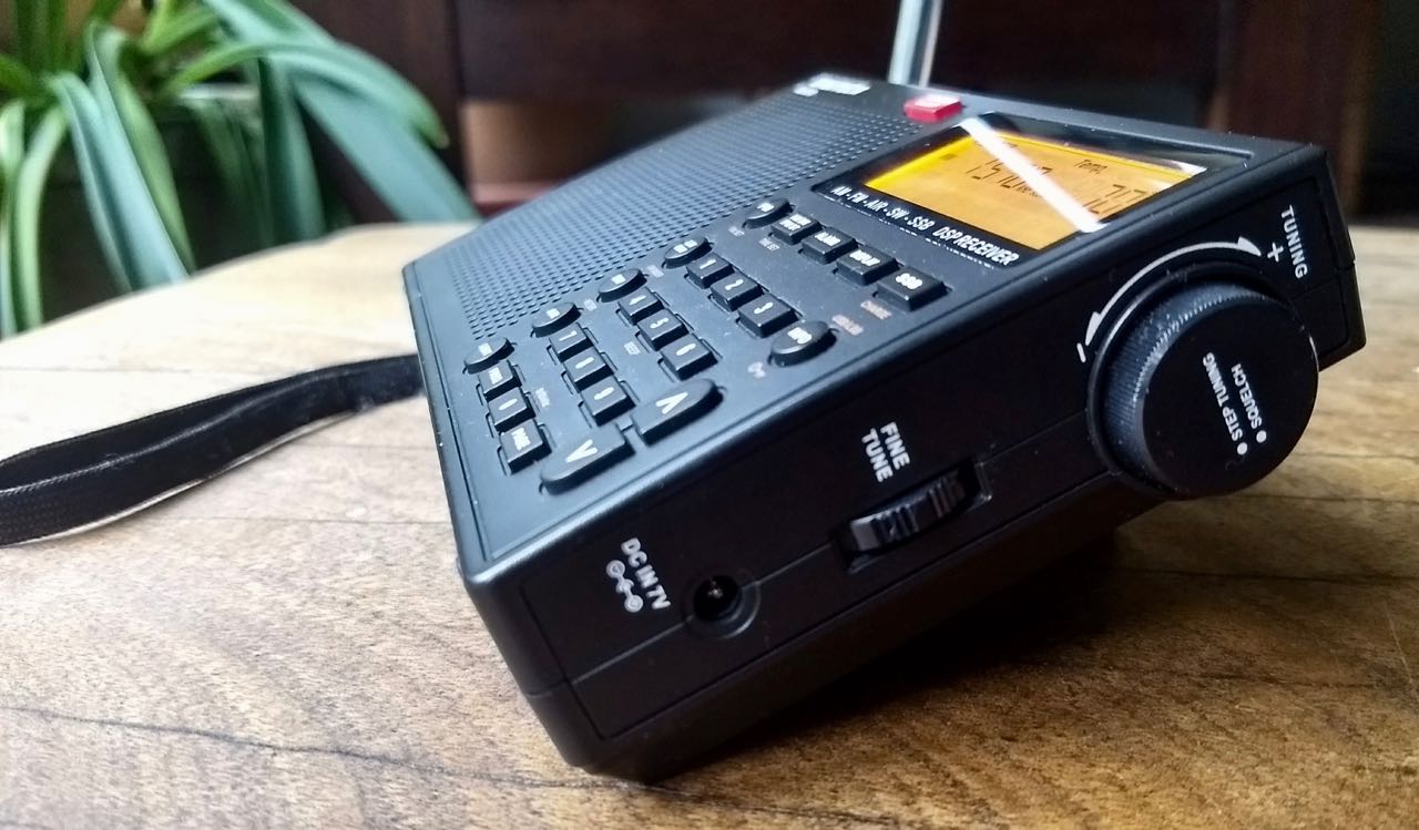
I especially like the fact the AR1780 has, on the right, a dedicated multi-function tuning knob. One can turn the tuning knob to scan frequencies or press it to cycle through fast or slow tuning steps (or to turn off this knob’s function entirely).
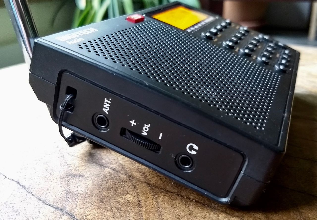
The AR1780 also has a dedicated fine tune control––a tuning wheel just beneath the main tuning knob also on the right side of the radio (see image above). The only odd quirk about this is that this is where most radios have a volume control. Being a creature of habit, many times I’ve inadvertently shifted frequencies when I simply wanted to turn up or down the volume! The volume control, meanwhile, is in the same position on the left side panel of the radio between the antenna and earphone jack.
Speaking of volume, the AR1780 can provide plenty of it-––almost room-filling audio––via the internal speaker. Best yet, I like its balanced fidelity: mellow, with notes of bass, but ample treble when listening at moderate volume. The audio response curve is almost ideal for such a small package.
Something else worth noting: the AR1780 fits nicely in the hand. In general, it’s a great size for portable listening.
Major bonus for a travel radio: the AR-1780 is powered by standard, accessible AA cells. Note that the frequency range information silk-screened on the back stand is incorrect–shortwave coverage extends up to 29,999 kHz.
On the downside, however, one negative I noted shortly after beginning use: muting between frequency steps. In AM mode, this is not as distracting as in SSB mode. Muting makes band scanning a more tedious and fatiguing experience. Unfortunately, in this era of DSP-chip-based receivers, it seems muting has resurfaced.
Also, as with many other DSP portables, you can often hear “input” noise when pressing buttons. In other words, if while listening to one frequency I decide to key in another, I’ll hear a little clicking or buzz in the audio as each button is pressed. This is a very minor annoyance since it only happens when buttons are pressed, nonetheless, I thought it worth mentioning. I often wonder if it’s a result of poor shielding, something from which similar models suffer.
Performance
Over the past two weeks, I’ve had the AR1780 on the air almost every day. I’ve compared it with a number of receivers, but mainly The C. Crane CC Skywave, The CountyComm GP5-SSB, and even the Grundig G6. Below, I break down my notes by band.
AIR band
Let’s start with the “bonus” band: the VHF aviation band.
I’m sure there a number of readers who’ll never use this band, but I am not one of them. Personally, I really enjoy listening to aviation traffic, especially when I travel by air. Since the advent of the AIR band on ultra-compact radios, I no longer feel like I have to lug an additional scanner or receiver just to listen to the local air traffic control; that’s a plus.
Performance-wise, the AR1780 seems to be equal with the CC Skywave on the AIR band. Like the CC Skywave, the AR1780 has a squelch control––a fantastic feature, indeed. Simply tune the radio to your favorite aviation frequency, press and hold in the tuning knob on the side, and then use the tuning knob to adjust the squelch level. I find level 3 or 4 works well.
Note that unlike the squelch on the CC Skywave, the squelch control on the AR1780 actually carries over to the shortwave band. If you have squelch set on the AIR band, then switch to another band where squelch isn’t needed, you will need to turn it off. I never use squelch on the shortwave or mediumwave/AM broadcast bands; normal fading (QSB) can trick the squelch to open and close while tuned to a frequency.
Another convenient feature: press and hold the AIR button to start an automatic scan of the entire band. It’ll run through the AIR band once, saving any active frequencies. This is an ATS feature, so only makes one pass. I wish you could set it to continuously scan the aviation band in a loop, much as a traditional scanner would.
FM
The AR1780 does a fine job on the FM band. It easily received my benchmark FM stations and even decoded the RDS from one broadcaster about 110 miles from my home base.
When listening to marginal FM signals, the AR1780 can be set to mono mode instead of default stereo mode.
What’s more, the internal speaker is exceptional at handling music––reasonably full fidelity given the limitations of the speaker size.
Longwave/Mediumwave
I’ll be the first to admit that longwave is not an easy band for me to evaluate. Here in North America, there are so few opportunities in the summer to log trans-Atlantic longwave stations. Indeed, unless I’m travelling to New England or the Canadian Maritime provinces, I never try to do so on a portable. I leave TA longwave DXing to my SDRs and tabletops back home where I can listen with the assistance of a large antenna.
But when I travel to Europe, longwave is a must, so my travel radio needs this capability. Based on my ability to receive benchmark LW airport beacons, I’m going to assume the AR1780 will do a fine job receiving European longwave stations while in Europe.
Likewise, the AR1780 should serve you well for both daytime and nighttime reception on mediumwave. Fortunately, switching between 10 and 9 kHz steps is simple: with the radio powered off, simply press and hold the “0” button to toggle between these steps.
On longwave and mediumwave, you can also use SSB mode (both upper and lower sideband). This could come in handy to reject adjacent signal interference on MW.
Likely an oversight on the part of the manufacturer, you can even engage the squelch feature, though why you would on LW and MW, I’m not sure.
Of course, with the fine-tuning control, you can navigate both bands in 1 kHz steps should you desire.
In short: the AR1780 is adequately sensitive on mediumwave and likely on longwave, as well. I wouldn’t rely on it for any serious DXing, but for a travel radio, it will serve you well.
Shortwave
Being first and foremost an avid shortwave listener, I spent the bulk of my AR1780 evaluation time on the shortwave bands and I’m overall very pleased with its performance.
In almost all of my comparisons on the shortwave bands, the AR1780 had a slight edge over its competition, namely, the CountyComm GP5-SSB, the Grundig G6, and the C. Crane CC Skywave.
To be clear, though, it was a very slight performance edge which I think may be attributed to the fact the AR1780’s telescopic antenna is longer, giving it a bit of gain over its competitors. For example, the AR1780’s antenna is about 17.7 cm (7 inches) longer than that of the smaller CC Skywave.
Still, placed on a table and not held in the hand, the AR1780 was able to pull in weak signals better than its competitors. I also compared it with the the Tecsun PL-680––one of my most sensitive shortwave portables––and, not surprisingly, the PL-680 outperformed the AR1780.
Again, I should stress that the sound from the AR1780’s internal speaker is more pleasant to listen to for extended periods than that of its smaller competitors.
SSB
Single sideband reception on the AR1780 is pretty impressive for a radio in this price class. On my particular unit, I found that the fine-tuning control was almost always needed to budge the frequency a few tenths of a kilohertz, even when I knew a particular signal was exactly on frequency. My Grundig G6 always had the same problem––indeed, sometimes in SSB mode, I had to listen “up” as much as 2 kHz on the G6.
The fine-tuning control works very effectively in SSB mode, nonetheless. Audio is quite pleasant, although the noise floor is not quite as low as it is on my larger portables like the Tecsun PL-680, PL-880, and the new S-8800. In my comparison tests, the AR1780 was slightly more sensitive than the CountyComm GP5-SSB, and about equal to that of the Grundig G6.
In short? SSB is a welcome, capable addition on this compact portable.
Summary
Every radio has its pros and cons, of course. When I begin a review of a radio, I take notes from the very beginning so that I don’t forget my initial impressions. Following is the list I’ve formed over the time I’ve been evaluating the Digitech AR1780:
Pros:
Display is clear and easy to read
Time is always present via display button
RDS info scrolls on lower line
Backlit display easy to read
Viewing angle good, save from top
Dedicated fine-tuning control (even on FM)
External antenna jack
9/10 kHz selectable MW steps
Time set is simple
Adjustable bandwidth in AM and SSB
Decent battery life from four standard AA cells
Audio from the built-in speaker has better fidelity than other radios in this size
Cons:
No bag or carry case
DC input voltage is an odd 7V
Muting between frequency changes, especially annoying in SSB
Sometimes keylock activates backlit display permanently
Scan function on AIR band doesn’t loop, it’s an ATS pass only
My AR1780 had incorrect information silk-screened on the back regarding frequency coverage
Minor: sluggish response when switching bands or modes
Conclusion
Is the Digitech AR1780 worth the price? I think so. For $129.00 AUD (roughly $103 USD), you’re getting a full-featured radio that is, by and large, a pleasure to operate. It has its quirks, but so do so many ultra-compact portables in this price bracket. It’s certainly worth considering if you live in Australia or New Zealand.
I’d like the AR1780 to be a little more refined:
No muting while band scanning in AM or SSB modes
A proper scan function to accompany squelch on the AIR band
Squelch that doesn’t carry over when bands are switched
What I do think is impressive for this price:
Overall smooth audio from the internal speaker
Dedicated external antenna port
Dedicated tuning and fine-tuning controls
Useful screen which displays time and even RDS information
Sturdy, relatively long telescoping whip antenna
These are features that make the AR1780 stand out among radios in its price class.
Is it a benchmark performer? No. But it does the job rather well for the price, and frankly, I think I’ll use this during travel occasionally, even though I have several other smaller portables.
Why? Well, for one thing, this radio has better audio fidelity from the internal speaker than most of my ultra-compact portables. When I’m in a hotel and listening to a local radio station or even a shortwave broadcaster that’s punching through typical hotel RFI, I’ll appreciate the richer, mellower audio. Many of my smaller portables are lacking in this respect, thus I usually end up listening through headphones.
In fact, the only thing this little receiver lacks for us here in North America is NOAA weather/Environment Canada radio frequencies––but it’s no wonder it’s not included, as it was never intended for this market. But I’m glad the step size on the AM broadcast band can be switched to our 10 kHz spacing, which makes it useful here in North America.
In short, the AR1780 has exceeded my expectations––though admittedly, it may be because it was my first experience with a Digitech radio and I had heard so many lukewarm reviews of previous models.
Regardless, I’m happy I paid a small premium to order this little rig from Down Under.
If you’re a radio enthusiast in Australia or New Zealand who wants the best performance in a portable, and doesn’t mind a larger radio, then do splurge for the Tecsun PL-660, PL-880, or Grundig Satellite. There is a dedicated Tecsun distributor in New South Wales and there are always, of course, retailers on eBay and one of my favorites, Anon-Co in Hong Kong.