Shortwave listening and everything radio including reviews, broadcasting, ham radio, field operation, DXing, maker kits, travel, emergency gear, events, and more
At first glance, iHeartMedia looks like the model 21st century media conglomerate, truly a colossus with interests across media: owner of 858 radio stations; Clear Channel Outdoor, one of the world’s largest outdoor companies; Premier Networks, the top U.S. radio network; and iHeartRadio, among the nation’s top digital music services.
The radio giant has a dynamic leader, Bob Pittman, the man who created MTV and widely regarded as one of the most charismatic men in media.
And it has glam, lots of glam. Look no further than the iHeartRadio Music Festival and other live events that draw thousands upon thousands of celebrants and endless media excitement.
But for all that glam, iHeart is a deeply troubled company. In fact, iHeartMedia is teetering on collapse. It’s not a question of whether it collapses but when, and it’s likely to come sooner rather than later. It could be within months.
What’s going to sink iHeart is its huge debt, some $21 billion. That’s more than the entire radio industry generates in ad dollars in a given year, and it’s a debt iHeart appears to have zero prospects of paying off.[…]
iHeart’s ills could not come at a worse time for radio.
Cumulus, the No. 2 radio company, is struggling to work through its own debt problems and could itself slide into bankruptcy. And CBS Radio was just put on the block in what’s seen as a major vote of no confidence in radio’s future by CBS Chairman Les Moonves.
One could well imagine a scenario in which all three companies are broken up and their stations all put on the market at one time, in what would prove a major disruption for the industry.[…]
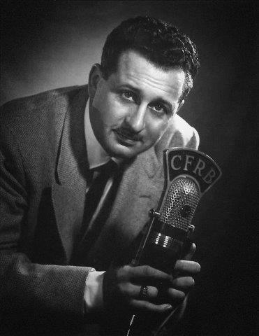
Many thanks to SWLing Post contributors, Richard Langley and Bill Patalon, who note the passing of legendary Canadian radio man, Wally Crouter.
Richard Langley comments:
I fondly remember listening to him over the years, particularly when I was working (during a couple of my undergraduate degree co-op program work terms) for Philips Electronics in Toronto as a QC inspector at the end of an assembly line for car radios. Yes, these used to be made in North America in the good old days. 😉 Of course, he was on shortwave, too, via CFRX.
Since I rely on a machine translation of the news page via Google Translate, I’m not totally clear about the details, but it appears Radio Belarus is shutting down their longwave, mediumwave and shortwave broadcasts on April 1, 2016.
UPDATE: SWLing Post contributor, Igor, comments with the following translation which was also confirmed by Ed:
Due to the fact that National Government Broadcasting Company of Belarus Republic refused services of the Belarus Radio and TV Transmitting Center, since April, 01 transmission of radio programs of “1 National Channel of Belarus Radio” and “Radiostation Belarus” on LW, MW and SW bands will stop:
– by transmitting center in Kolodishci: – “1 National Channel of Belarus Radio” on 7255 KHz, 250 KW – “Radiostation Belarus” on 11930 KHz, 250 KW – “Radiostation Belarus” on 11730 KHz, 150 KW – “1 National Channel of Belarus Radio” on 6080 KHz, 150 KW – by Osipovich transmitting center in Sosnovy: – “1 National Channel of Belarus Radio” on 279 KHz, 500 KW – “Radiostation Belarus” on 1170 KHz, 800 KW
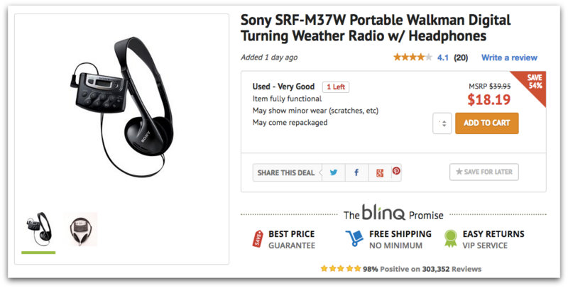
I just noticed that Blinq.com has a “Used – Very Good” Sony SRF-M37W AM/FM/WX digital walkman with headphones for $18.19 shipped.
While I don’t think the SRF-M37W will win any DXing awards, it is a very practical and lightweight portable for outdoor/active use (hiking, walking, running, biking, etc). I was mighty tempted to purchase this one and mount it on my mountain bike, but I have other portables that could do the job.
Features:
Digital AM/FM/Weather stereo tuner
Direct weather and preset access buttons
20-station preset memory
Digital LCD digital with clock and battery indicators
Many thanks to SWLing Post contributor, Jerry Popiel, for the following guest post:
A MW DXing Powerhouse Mini FSL Antenna
by Jerry Popiel
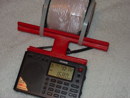
In late February 2016 I completed construction of a modified version of Gary DeBock’s excellent 3 inch Mini FSL design (click here to view).
This new antenna is nothing short of a AM DXing powerhouse with unbelievable sensitivity for receiving stations across the entire AM Bandwidth both day and night. The tuning of stations is razor sharp and it has stunning nulling qualities. Consultation assistance was provided from DXing experts Steve Ratzlaff and Gary DeBock on the project.
Construction Details:
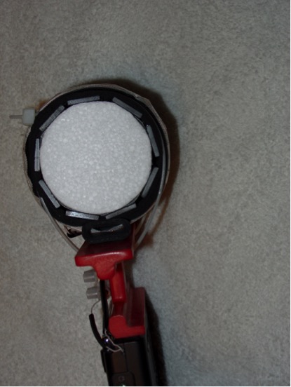
The Antenna was constructed using 9 – 100 mm Ferrite Bars wound on a 2.75 inch diameter x 4 inch styrofoam cake dummy form custom made by in Vancouver, B.C. Canada – ([email protected]) for $3.50 plus shipping.
The Coil wire consisted of 38 turns of high gain 660/46 Litz Wire. (Note: As can be seen 38 turns of the thicker Litz Wire left only 5/8” of room on each side of the Styrofoam Form to wire wrap the coil to the ruler frame. A longer Form ie 5” long would work much better for this build).
The insulation spacer used was 2 layers of 1/8 inch Aerotape self adhesive tape which also helped hold the 100 mm Ferrite Bars onto the Styrofoam Coil Form. Inductance measured 356 uH using a DM 4070 Meter which is well within the requirement of over 300 uH for AM Band Reception.
Side View Of 9-Bar FSL Antenna with 2.75” Diameter Styrofoam Cake Dummy.
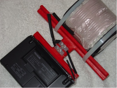
Because of the extra thickness of high gain 660/46 Litz Wire which is a bit too big to solder to the inside terminals of the Tecsun PL-380 Radio, a 2 Position Terminal Block was superglued to the outside of the Ruler Frame to act as an interface connection point.
2 Position Terminal Block Superglued To Back Of Antenna Frame
Testing Results:
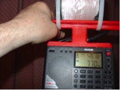
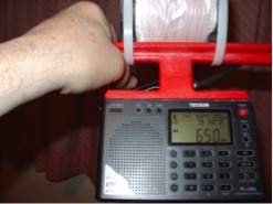
Both daytime and evening AM station captures have been spectacular. Stations as far away as KKOB / 770 kHz Alberquerque, New Mexico 1130 Miles from here in Winnipeg, Manitoba, Canada have been received. Country music station WSM / 650 kHz in Nashville, Tennessee 1082 miles distant is a daily evening pickup.
Station KKOB / 770 kHz Alberquerque, New Mexico 1130 Miles distance.
Station WSM / 650 kHz in Nashville, Tennessee 1082 miles distance.
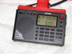
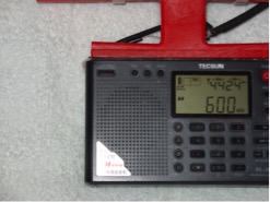
Two Stations Received At 600 kHz 90 Degrees apart at the same time:
The amazing Nulling and Razor Sharp Tuning quality of this FSL was demonstrated when 2 stations at 600 kHz were received at the same time by rotating the Radio with attached FSL 90 degrees. In the North / South direction Station KSJB / Jamestown, North Dakota (219 miles distant) was received with a strong signal strength of 50 / 23. Then by rotating the Radio 90 degrees to the East / West direction Saskatoon, Saskatchewan station CJWW (442 miles distance) was captured with a similar strong signal strength of 44 / 24.
600 kHz Station KSJB / Jamestown, North Dakota.
600 kHz Station CJWW / Saskatoon, Saskatchewan.
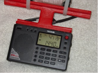
Daytime Reception of 600 Watt Station 137 Miles Distant:
A major daily AM reception capture during the afternoon illustrating the amazing sensitivity of this antenna is 600 Watt station KKXL Sports Radio 1440 kHz (137 miles).
All Indoor Reception – For Now!
Due to winter conditions here in Winnipeg, all of the amazing station reception captures in this report were done inside the House facing towards the South window. Fortunately the red ruler platform sides can he used as handles when pointing the radio in the direction of best reception. Exciting times are ahead to see how well this mini 3” FSL will perform outdoors for likely even better AM DXing.
Summarizing:
The design of this new FSL Antenna attached to the Tecsun PL-380 Ultralite radio by Gary DeBock is a major breakthrough in AM DXing since the Radio is attached to the FSL. This new FSL Antenna needs to be constructed to be really appreciated. The application described here requires a bit more skill to construct and is also heavier than the original construction – but at least it is portable. For beginners Gary’s original 3” FSL Heathkit Design is highly recommended and can be reviewed in his You Tube Video posted at: https://www.youtube.com/watch?v=VY9u8MReGjk
Thanks,
Jerry Popiel
Winnipeg, Manitoba, Canada
Thank you, Jerry! It’s amazing what performance you and Gary DeBock have gotten out of these homebrew FSL antennas! Thank you so much for taking the time to share your construction details and performance notes!
The Society of Broadcast Engineers (SBE) has told the FCC that the regulatory agency needs to take another tack in its efforts to tackle AM revitalization. If the FCC takes the SBE’s advice, the result could be less noise in the MF and HF Amateur Radio bands. In comments the SBE filed in response to an FCC Further Notice of Proposed Rulemaking and Notice of Inquiry (MB 13-249) proposing ways to enhance the viability of the AM broadcast service, the SBE said the Commission must “commit to a regulatory plan which, over time, will reduce the levels of man-made noise in the MF bands, and more broadly in the bands below 30 MHz.” In comments it filed earlier in the proceeding, the SBE pointed out that “AM radio in particular is susceptible to interference from electronic devices of all types,” and that ambient noise on the AM band is only bound to get worse with further proliferation of noise-generating electronic devices, including certain lighting devices regulated under FCC Part 15 and Part 18 rules.[…]
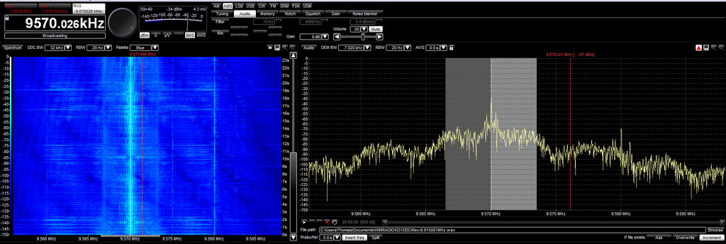
Each morning, I enjoy listening to Radio Australia on 9,580 kHz, but I’m forced to tune elsewhere due to interference when China Radio International starts broadcasting on 9,570 kHz, via Radio Havana Cuba’s relay.
Hypothetically I should be able to mitigate any adjacent interference from CRI by listening to Radio Australia’s upper sideband. But unfortunately, RHC’s transmitters spew spurious emissions a full 20 kHz on either side of their carrier. It’s most annoying.
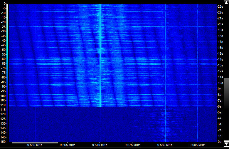
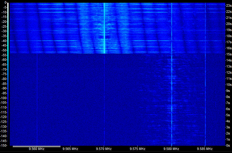
Here’s what my waterfall looked like when CRI signed off:
Notice how clear the 35 kHz waterfall window became (that’s Radio Australia centered on 9850 kHz):
The reason for this is clear: obviously, some of RHC’s transmitters are in need of care–and they’re not the only ones.
Radio Cairo
I’ve received a number of requests from Radio Cairo to post notices about their English language broadcasts. Normally, I’m quite happy to post press releases, but in each case I’ve mentioned that their English broadcasts are almost impossible to understand. For years, RC has had a problem with AM modulation (I assume) and, to my knowledge, have never addressed it.
I’ve sent RC feedback on a number of occasions; in response, I’ve received only the inconclusive reply that they’re “looking into the situation.”
To underscore the point, on Sunday Andrea Borgnino shared the following video/audio of Radio Cairo via Twitter.
There are other broadcasters that emit messy signals, but Radio Havana Cuba and Radio Cairo are the most noticeable in my listening area. And, it seems, neither broadcaster is in any hurry to address their ongoing problems.
In Radio Cairo’s case, especially, the broadcaster is simply wasting money by attempting to broadcast a signal that can neither be received nor interpreted. It’s rather sad. Ultimately, one has to wonder why they bother to broadcast at all…
Radio Havana Cuba, China Radio International, and Radio Cairo (among others) take note: a little care of your radio transmitters will go a long way toward increasing your listenership.
What you can do: Consider contacting broadcasters when when you become aware of transmitter problems. Despite RC’s notable exception, oftentimes a broadcaster may not be fully aware of the issue––thus your feedback is necessary to help correct the problem.

 (Source: MediaFire)