The Par EndFedz EFT-MTR triband (40/30/20M) antenna
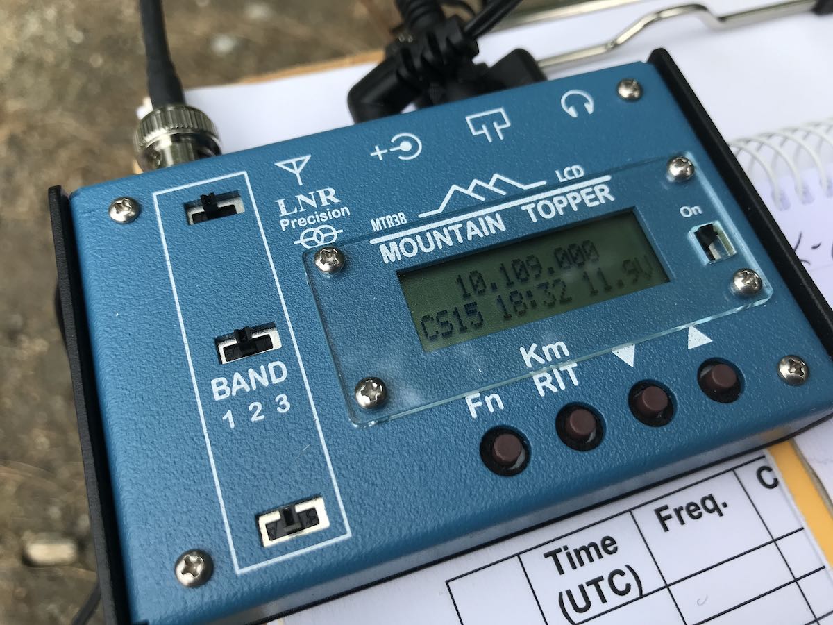
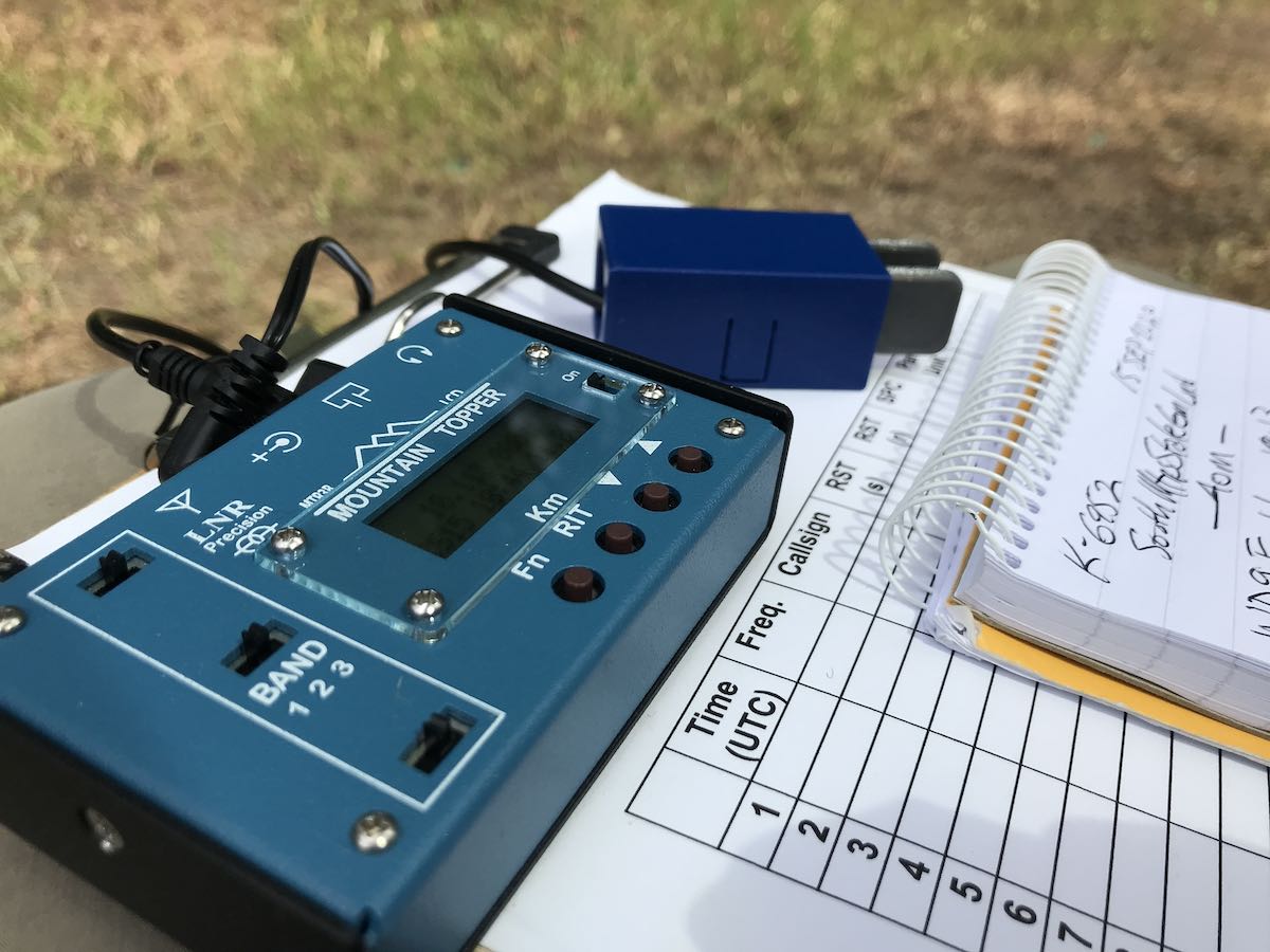
In July, I purchased a tiny QRP transceiver I’ve always wanted: the LnR Precision MTR-3B. It’s a genius, purpose-built little radio and a lot of fun to operate in the field.
It’s also rather bare-bones, only including a specific feature set built around ultra-portable CW operation.
While the MTR-3B has features like CW memory keying, a wide operating voltage (6-12 VDC), extremely low operating current (20 ma in receive), real-time 24 hour clock, and a full compliment of keying adjustments, it lacks other features like a volume control, SWR meter, speaker, and built-in antenna tuner.
Some of those may seem like big omissions but SOTA and POTA activators who like extremely lightweight/portable gear love the MTR-3B for being so purpose-built.
The MTR-3B (and its predecessors) operate on three bands: 40, 30, and 20 meters. These are, without a doubt, my favorite bands when operating portable since antenna lengths are reasonable.
Since the MTR-3B doesn’t have an internal ATU, you need to pack an external tuner or, better yet, a resonant antenna–ideally, one that can be used on all three bands.
Although many of my portable transceivers have built-in ATUs, I rarely use them because I primarily operate with resonant antennas. Resonant antennas are more efficient–giving you the maximum mileage per watt. In addition, they’re also more simple: connect them to the rig and hop on the air. No tuner or tuning required.
Since I keep self-contained field radio kits, my MTR-3B needed a dedicated resonant antenna.
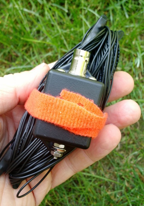
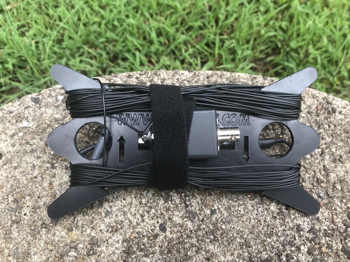
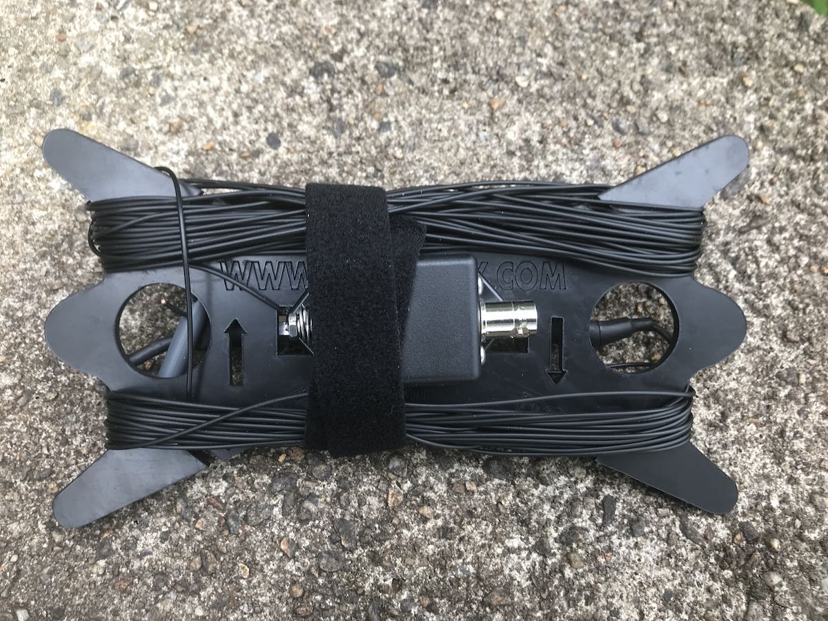
The EFT Trail-Friendly antenna is incredibly compact and quite easy to deploy.
I’ve mentioned in previous posts that I’m a big fan of the Par EndFedz Trail-friendly EFT tri-band antenna (above) which is resonant on 40, 20, and 10 meters. I’ve activated well over 130 parks with this little antenna.
After I took delivery of the MTR-3B, I borrowed the Trail-friendly EFT antenna from my KX2 field kit. It worked well on 40 and 20 meters, but it doesn’t cover the 30 meter band. Also, by borrowing the EFT from the KX2 kit, I broke one of my rules: never borrow from one field kit to feed another. This led to me leaving the EFT hanging in a tree at a remote park and returning a week later–a three hour round-trip(!!!)–to retrieve it. (FYI, in all fairness, I also blamed my trusty canine companion for this mishap!)
Enter the Par EndFedz EFT-MTR triband antenna
A few months ago, Vibroplex purchased the Par antenna line from LnR Precision.
I was very pleased with this decision as I’m guessing LnR Precision wanted to hand off antenna production so they could focus on the very popular Mountain Topper transceiver line.
Vibroplex is owned by my buddy, Scott Robbins (W4PA), who is not only a successful entrepreneur, but also an award-winning contester and DXer. I’ve known Scott for years and knew he’d not only be a great steward of the Par product line, but also push new innovations.
I emailed Scott asking if Vibroplex had a field-portable antenna that would be resonant on 40, 30, and 20 meters. Turns out, there’s a Par antenna designed specifically to pair with the MTR-3 series transceivers: the Par EndFedz EFT-MTR.
Scott pointed me to a description of the antenna on the Vibroplex website:
The new EndFedz ® EFT-MTR is a 40m/30m/20m tri-band QRP antenna rated up to 25 watts. The “MTR” name was selected as LNR Precision developed this antenna to be the perfect companion to the wildly popular 40/30/20m Mountain Topper QRP transceiver. The EFT-MTR’s total length is 65′ of 22 AWG polystealth wire and weighs less than 4 ounces! It is built with the same high level of workmanship and quality that you have come to expect with all EndFedz ® antennas.
A particular innovation on this antenna: This EndFedz is a little different than previous designs. The user has the option to remove an SMA connector at the end of the 30M resonator to enable just 30 meters, or keep the SMA installed for 40 and 20 meters. Because of the broad bandwidth of the antenna, it is unlikely that it will require tuning in the vast majority of deployments. This is particularly true of 30 meters where the band is very narrow. As our tagline states, “They Just Work!”
Included with the EFT-MTR is the EndFedz Antenna Winder. Conveniently allowing winding up the antenna line to not have a tangled mess at the end. The winder will hold both the antenna and 25 feet of RG-174U coaxial cable (optional accessory).
Scott offered to send me an EFT-MTR to evaluate in the field (disclaimer: at no cost to me) and I accepted without hesitation, of course!
An EFT-MTR field review
 I’ve taken the EFT-MTR antenna to three park activations at this point and have formed some opinions about it.
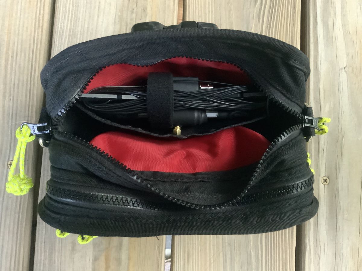
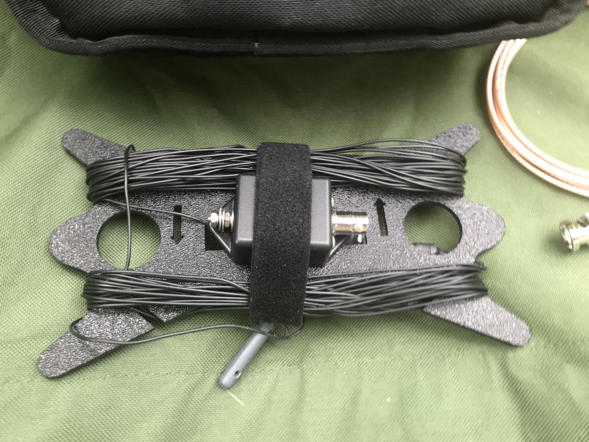
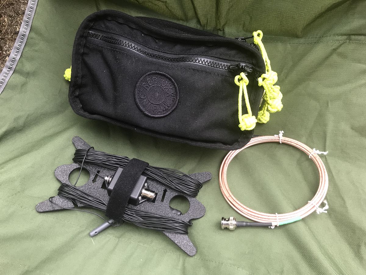
The EFT-MTR fits perfectly in a slide-in pocket in the main compartment of the Boot Boss.
First of all, I couldn’t be more pleased with the size as it fits perfectly in my MTR-3B field kit built around my Red Oxx Booty Boss pack.
I really like the built-in antenna winder: it’s larger than that of the EFT Trail-Friendly, but also much easier to wind up and manage post-activation.
I’ll admit, the length of the EFT-MTR was a bit surprising the first time I deployed it: 65 feet. Keep in mind, though, I had been used to a much shorter 41 foot radiator on the EFT Trail-friendly. Occasionally, I operate in spots where I simply don’t have the room to deploy a long antenna. I also worried that the EFT-MTR resonance might be negatively affected by winding its way through trees and over a branches. The MTR-3B transceiver does not like high SWR values and has no built-in SWR meter to monitor it. Last thing I wanted to do was harm the MTR finals.
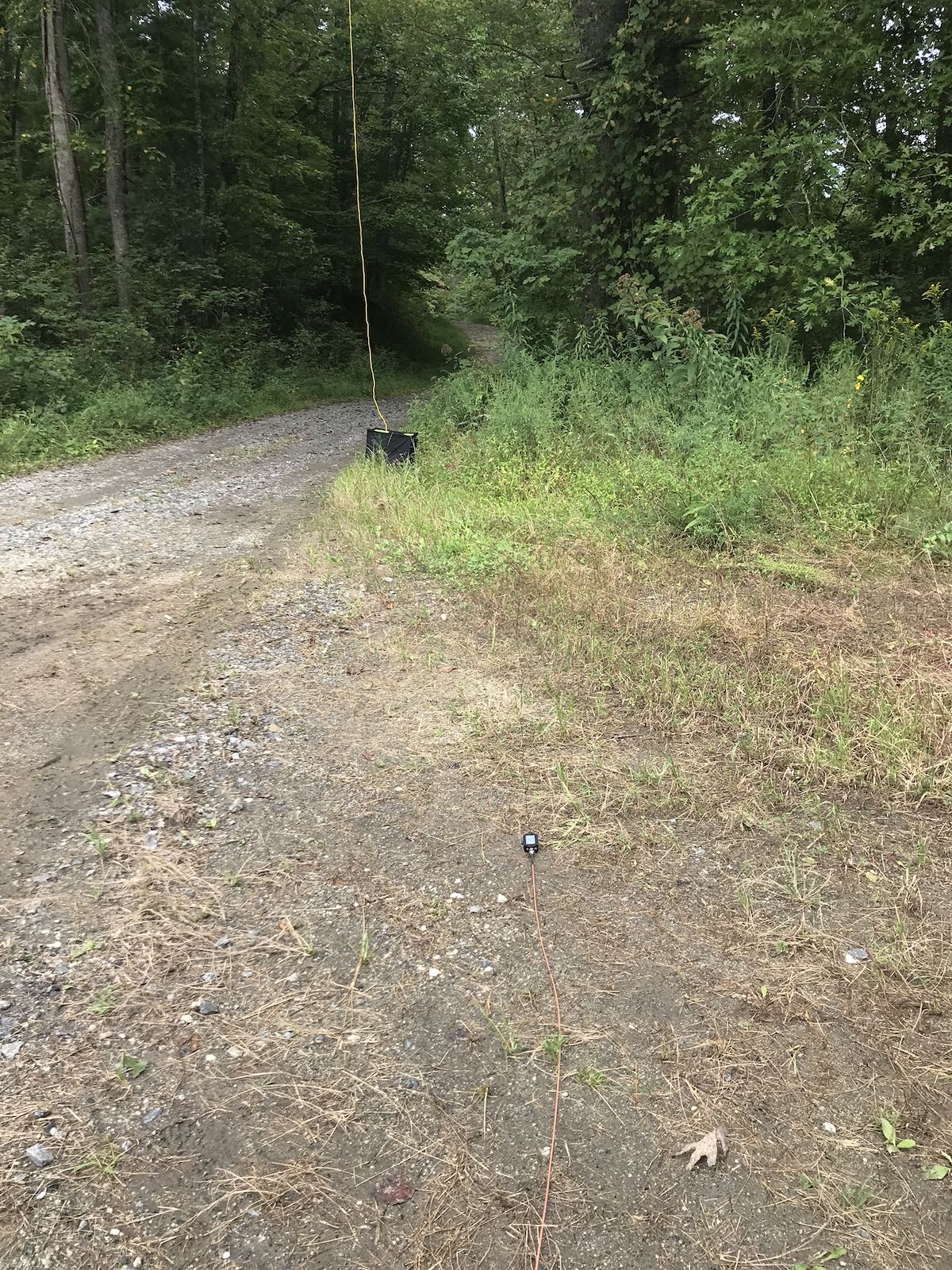
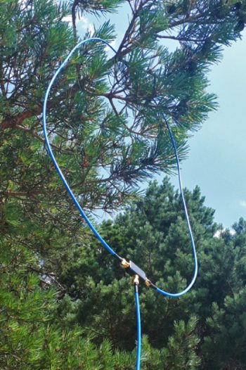
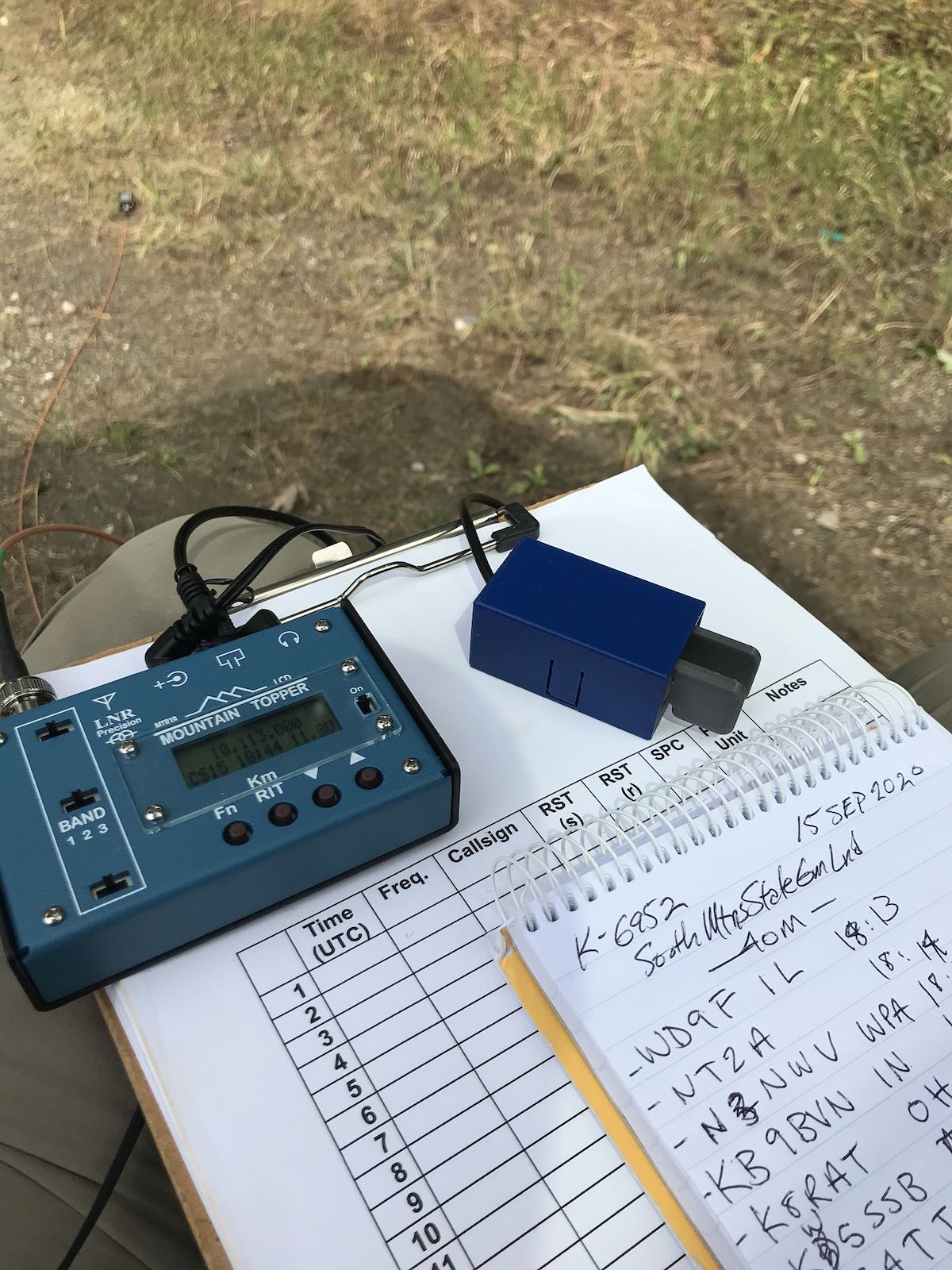
You might be able to spot the feed point of the EFT-MTR at my activation of K-6952 this week.
Fortunately, winding its way through trees doesn’t seem to have a significant impact on SWR.
Each time I’ve taken the EFT-MTR to the field, I’ve also taken my KX2 which I’ve used to read the antenna’s SWR value. So far, the difference has only been negligible and SWR well within the tolerances of the MTR-3B. Score!
I should note here that since I’ve started using an arborist throw line, I’m also able to hang antennas much higher than I could before. This has had a huge impact on all of my field activities.
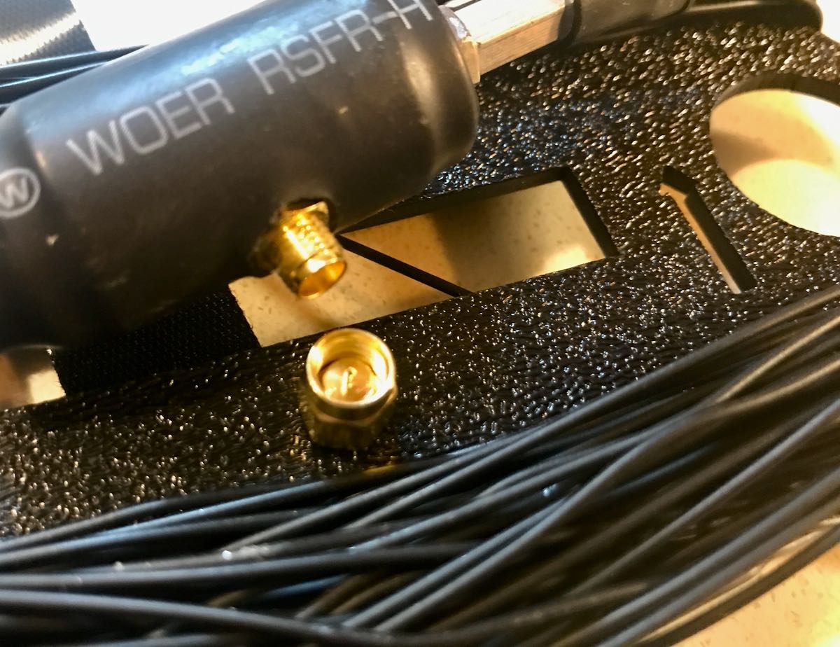
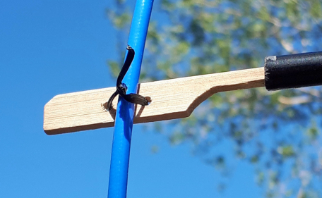
Removing the SMA cap changes the EFT-MTR from a 40/20 to a 30 meter resonant antenna.
To be resonant on 40, 20 and 30 meters, the EFT-MTR requires a field modification. On the coil about 2/3 the way up the antenna, there’s an SMA connector with a small screw on cap (see above). When the cap is on (thus completing the connection) the antenna is resonant on 40 and 20 meters. You must remove the cap for it to be resonant on 30 meters.
Since I’ve been using the EFT-MTR, I start an activation on 40 meters (which is typically my most productive band), then move to 20 meters (typically, my least productive). If I have the time, or need the extra contacts to confirm a valid activation, I lower the antenna, unscrew the SMA cap, and raise the antenna again.
I thought at first this would be a major pain, but it hasn’t. Now that I’m using an arborist throw line, it’s super easy to lower and raise antennas. But even when I’ve used fishing line, it really hasn’t been an issue.
The only issue I see is I’m afraid I’m going to lose that little SMA cap in the field. To prevent this, I’ve made it a routine to immediately put it in the internal zippered compartment of the Booty Boss pack. I might find a source for those caps, though, just in case I still lose this one.
I’ve been very pleased with the EFT-MTR’s performance. I’m guessing it’s actually higher gain than my beloved EFT Trail-Friendly antenna. On my last activation with the EFT-MTR, I knocked out eight 40 meter contacts in about eight minutes during a period of poor propagation. Note that the MTR-3B was only pushing 3 or 4 watts of power.
I then moved to 20 meters where, frankly, propagation was so crappy I didn’t hang out there long. Instead, I lowered the antenna, removed the SMA cap, and started calling on 30 meters. Within a few minutes, I racked up the rest of my contacts.
I was very pleased with how quickly the Reverse Beacon Network picked up my CQs and was thus auto-spotted on the POTA website.
Conclusion?
If you own a Mountain Topper MTR-3 series transceiver, I highly recommend the EFT-MTR antenna. As with my EFT Trail-friendly and Par sloper, the quality is top-shelf. I expect the EFT-MTR will last even longer than the EFT Trail-friendly since the winder is so accommodating and the in-line coil is designed so that it doesn’t snag on branches as easily.
I’m looking forward to much more field fun with the MTR-3B and EFT-MTR combo!
Click here to check out the EFT-MTR at Vibroplex.
Click here to check out Vibroplex’s full line of antennas.
Many thanks again to Scott at Vibroplex for sending me the EFT-MTR for evaluation!

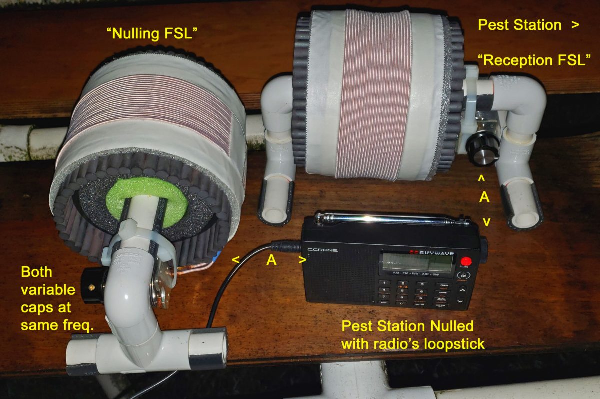 Nulling a local pest with dual FSL Loops